

Top
Abstract
Lenovo BladeCenter® remains an innovative solution to running business solutions. BladeCenter H efficiently integrates servers, storage, networking, I/O, and applications, which enables organizations to build flexible IT infrastructures by using common building blocks. In 9U of rack space, the BladeCenter H chassis can contain up to 14 blade servers, 10 switch modules, and four power supplies to provide the necessary I/O network switching, power, and cooling to support the individual servers.
Withdrawn: BladeCenter H is now withdrawn from marketing.
Change History
Changes in the October 28 update:
- Updated the I/O module tables to indicate withdrawn modules
- Added a section on Top-of-rack Fibre Channel switches
Introduction
BladeCenter® remains an innovative solution to running business solutions. BladeCenter H efficiently integrates servers, storage, networking, I/O, and applications, which enables organizations to build flexible IT infrastructures by using common building blocks. In 9U of rack space, the BladeCenter H chassis can contain up to 14 blade servers, 10 switch modules, and four power supplies to provide the necessary I/O network switching, power, and cooling to support the individual servers.
Figure 1 shows the BladeCenter H chassis.
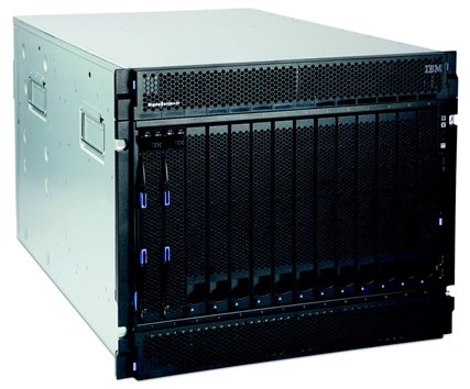
Figure 1. The BladeCenter H chassis
Did you know?
BladeCenter H delivers high performance, extreme reliability, and ultimate flexibility to even the most demanding IT environments.
The chassis supports up to four traditional fabrics by using networking switches, storage switches, or pass-through devices. The chassis also supports up to four high-speed fabrics for support of protocols such as 40 Gb InfiniBand or 10 Gb Ethernet. The built-in media tray includes light path diagnostics, two front USB inputs, and an optical drive.
Key features
This section lists the key features of the BladeCenter H chassis.
Scalability and performance
The BladeCenter H chassis offers numerous features to boost performance and improve scalability:
- Up to 14 servers with support for the latest generation of BladeCenter blades, helping provide performance and investment protection.
- Virtual Fabric offers up to 18 I/O ports on a single-wide blade and up to 10 I/O modules in a single chassis, with the choice of Ethernet, Fibre Channel, FCoE, InfiniBand, iSCSI, and SAS connectivity.
- BladeCenter H supports port speeds of up to 40 Gbps.
- BladeCenter H provides up to 1.92 Tbps of switching capacity with up to four Virtual Fabric 10 Gb switches.
- A flexible and scalable architecture with integrated servers and networking, storage, and management infrastructure supports your growing business needs.
Manageability and security
Powerful systems management features simplify local and remote management of the BladeCenter H chassis:
- The high degree of integration in the BladeCenter H chassis reduces the need for server components, replacing numerous fans, KVM and Ethernet cables, power supplies, external switches, and other components.
- The BladeCenter H chassis includes an Advanced Management Module (AMM). The AMM boosts administrator productivity and reduces skill level requirements, which can help reduce costs, improve overall productivity, and make administration easier, by providing a single point of control for the solution. The AMM supports many industry-standard and open protocols.
- The AMM provides extensive security features, including role-based user authentication and access control, LDAP support, and SSH and SSL protocols for secure remote systems management.
- IBM Systems Director remains a powerful and intelligent solution to manage BladeCenter systems along side rack mount and tower servers. Systems Director uses the hardware’s capabilities by surfacing pertinent information about your blade server. The easy-to-use wizards provide step-by-step instructions and offer automated deployment capabilities.
- IBM Fabric Manager simplifies the deployment of infrastructure connections by managing network and storage address assignments.
- IBM FastSetup simplifies, automates, and speeds up the deployment process from server power-up to production, making BladeCenter easier to manage, deploy, and maintain.
Availability and serviceability
The BladeCenter H chassis provides many features to simplify serviceability and increase system uptime:
- BladeCenter reduces the number of parts that are required to run the system. Sharing fans, power supplies, systems management, and ports means that there are fewer parts to buy and maintain, and fewer components that can fail and cause downtime.
- Hot-swap components, such as the server, switches, power supplies, and blowers, ensure maximum uptime.
- Redundant components, such as blowers and power supplies, ensure that systems can remain available even during hardware maintenance windows and failures.
- The Predictive Failure Analysis (PFA) detects when system components operate outside of standard thresholds and generates proactive alerts in advance of possible failure, therefore increasing uptime.
- Dual independent power and signal connectors to the BladeCenter H chassis midplane provide fault tolerance to increase uptime.
- The light path diagnostics panel and individual light path LEDs quickly lead the technician to failed (or failing) components. These features simplify servicing, speed up problem resolution, and improves system availability.
- A 3-year customer replaceable unit and onsite limited warranty and next business day 9x5 provides an additional peace of mind.
Energy efficiency
The BladeCenter H chassis offers the following energy-efficient features to save energy, reduce operational costs, increase energy availability, and contribute to a green environment:
- The energy-efficient components and component-sharing design of the BladeCenter chassis provides ultimate power and cooling savings.
- BladeCenter H helps reduce energy costs with leadership high-efficiency power supplies that are 94% efficient and 80 PLUS Platinum Certified.
- The BladeCenter H uses hexagonal ventilation holes, a part of Calibrated Vectored Cooling™ technology. Hexagonal holes can be grouped more densely than round holes, providing more efficient airflow through the system.
- IBM Systems Director Active Energy Manager™ provides advanced power management features with actual real-time energy monitoring, reporting, and capping features.
Locations of key components
Figure 2 shows the front of the BladeCenter H chassis.
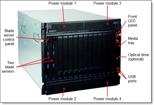
Figure 2. Front of the BladeCenter H chassis
Figure 3 shows the rear of the BladeCenter H chassis
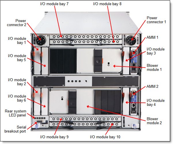
Figure 3. Rear of the BladeCenter H chassis
Standard specifications
Table 1 lists the standard specifications.
Table 1. Standard specifications
| Components | Specification |
| Machine type | x-config: 8852, e-config: 7989. |
| Form factor | 9U rack-mounted unit. |
| Server bays | 14. |
| Servers supported | Intel Xeon processor-based HS12, HS22, HS22V, HS23, HS23E, and HX5 servers. IBM POWER® processor-based PS700, PS701, PS702, PS703, and PS704. Certain older BladeCenter servers. |
| Standard I/O bays | Six (Bays 1 - 6). Bays 1 - 4 support 1 Gb Ethernet, 4 Gb and 8 Gb Fibre Channel, and 3 Gb SAS I/O modules. Bays 3 - 6 support Ethernet-to-Fibre Channel bridge I/O modules. |
| High-speed I/O bays | Four (bays 7 - 10). Bays 7 - 10 support 10 Gb Ethernet, 10 Gb converged fabric, and 40 Gb InfiniBand I/O modules. With a Multi-switch Interconnect Module (MSIM), bays 7 - 10 support 1 Gb Ethernet and 4 Gb and 8 Gb Fibre Channel I/O modules. |
| Connectivity type | Ethernet, Fibre Channel, Fibre Channel over Ethernet (FCoE), InfiniBand, iSCSI, and SAS. |
| Management modules | Up to two redundant hot-swap Advanced Management Modules (AMM): One AMM is standard, and the second AMM is optional. |
| Optical drive bays | Media tray: One. There is support for an optional DVD-ROM or Multi-burner. |
| Ports | AMM: One DB-15 video port, two USB 2.0 ports for keyboard and mouse, one RJ-45 serial port, and one RJ-45 10/100 Mb Ethernet port for remote management. Media tray: Two USB 2.0 ports. Rear: One serial breakout port for optional serial breakout cable. |
| Cooling | Calibrated Vectored Cooling with two standard or enhanced redundant hot-swap blower modules (model dependent). You can have up to four fan packs with power modules (one fan pack per each power module). |
| Power modules | Up to four redundant hot-swap 2900 W (older models) or 2980 W power modules support two power domains; redundancy is provided within a pair in the same power domain. Power modules 1 and 2 supply power to server bays 1 - 7; power modules 3 and 4 supply power to server bays 8 - 14. (See the "Power modules" section for details.) |
| Hot-swap parts | Servers, I/O modules, management modules, media tray, power modules, and blowers. |
| Systems management | AMM, light path diagnostics, Predictive Failure Analysis, IBM Systems Director, and IBM Systems Director Active Energy Manager. Remote presence (graphics, keyboard and mouse, and virtual media) through AMM. |
| Security features | User-based security, user profiles, LDAP, SSH, and SSL. |
| Limited warranty | 3-year customer-replaceable unit and onsite limited warranty with 9x5/next business day response time. |
| Service and support | Optional service upgrades are available through warranty upgrades: 9x5 or 24x7 4-hour or 2-hour response time, 1-year or 2-year warranty extension. |
| Dimensions | Height: 400 mm (15.8 in.), width: 483 mm (19.0 in.), depth: 711 mm (28.0 in.) |
| Weight | Minimum: 41 kg (90 lb), maximum 159 kg (350 lb) |
Models
Table 2 lists the specifications of the standard BladeCenter H models.
Withdrawn: BladeCenter H is now withdrawn from marketing.
Table 2. BladeCenter H standard models
| Feature | Specifications | |||
| Machine type/model | 8852-5Tx† | 8852-94x† | 8852-95x† | 8852-96x† |
| Server bays (total / open) | 14 / 14 | 14 / 14 | 14 / 14 | 14 / 14 |
| Management modules (std. / max.) | 1 / 2 | 2 / 2 | 2 / 2 | 2 / 2 |
| Standard I/O bays (total / open) | 6 / 6* | 6 / 4* | 6 / 4* | 6 / 2* |
| High-speed I/O bays (total / open) | 4 / 4 | None | 4 / 2 | 4 / 2 |
| I/O modules standard | None | 2x Server Connectivity Module 2x Brocade Converged 10GbE Switch Module |
2x Server Connectivity Module 2x Cisco Nexus 4001I Switch Module |
2x Server Connectivity Module 2x Virtual Fabric 10Gb Switch Module 2x QLogic Virtual Fabric Extension Module |
| SFP+ transceivers standard | None | 4x Brocade 8Gb SFP+ SW Optical Transceiver 8x Brocade 10Gb SFP+ SR Optical Transceiver |
8x Cisco 10GBASE-SR SFP+ Transceiver | 8x 10GbE 850 nm Fiber SFP+ Transceiver (SR) 4x 8Gb SFP + SW Optical Transceiver |
| Software standard | 1x BladeCenter Open Fabric Manager Basic | 1x BladeCenter Open Fabric Manager Basic | 1x BladeCenter Open Fabric Manager Basic | |
| Power supplies (std. / max.) | 2x 2980 W / 4 | 4x 2980 W / 4 | 4x 2980 W / 4 | 4x 2980 W / 4 |
| Enhanced blowers (std. / max.) | 2 / 2 | 2 / 2 | 2 / 2 | 2 / 2 |
| Optical drive | Optional | Multi-burner | Multi-burner | Multi-burner |
† x is a region-specific letter (for example, the EMEA MTM is 88524TG, and the US MTM is 88524TU).
* Two standard I/O bays (bays 3 and 4) can be used for either standard I/O modules or bridge I/O modules. For details, see the "I/O architecture" section.
Supported servers
Table 3 lists the blade servers that are supported in the BladeCenter H chassis. The table also lists the maximum number installable items based on thermal design power (TDP) of the Intel Xeon processor that is installed in the servers.
| Blade server | CPU TDP | Maximum number of servers per BladeCenter H chassis | |||
| 2900 W power supplies | 2980 W power supplies | ||||
| Standard blowers | Enhanced blowers | Standard blowers | Enhanced blowers | ||
| BladeCenter HS12 (8028) | All | 14 | 14 | 14 | 14 |
| BladeCenter HS22 (7870) BladeCenter HS22V (7871) |
130 W | None | 14 | None | 14 |
| 95 W | 6+6 | 14 | 14 | 14 | |
| Up to 80 W | 14 | 14 | 14 | 14 | |
| BladeCenter HS23 (7875, E5-2600 v2) | Up to 130 W (excl. 80 W)† | None | 14* | None | 14 |
| 80 W† | 14** | 14 | 14** | 14 | |
| 95 W# | 14**§ | 14 | 14**§ | 14 | |
| 70 W# | 14** | 14 | 14** | 14 | |
| 50 W# | 14 | 14 | 14 | 14 | |
| BladeCenter HS23 (7875, E5-2600) | Up to 130 W (excl. 80 W) | None | 14 | None | 14 |
| 80 W | 14 | 14 | 14 | 14 | |
| BladeCenter HS23E (8038) | Up to 95 W | 14 | 14 | 14 | 14 |
| BladeCenter HX5 (7872 and 7873) single-wide | 130 W | None | 10 | None | 12 |
| Up to 105 W | 14 | 14 | 14 | 14 | |
| BladeCenter HX5 (7872 and 7873) + MAX5 double-wide | 130 W | 6 | 6 | 7 | 7 |
| Up to 105 W | 7 | 7 | 7 | 7 | |
| BladeCenter PS700 | All | 14 | 14 | 14 | 14 |
| BladeCenter PS701 | All | 14 | 14 | 14 | 14 |
| BladeCenter PS702 | All | 7 | 7 | 7 | 7 |
| BladeCenter PS703 | All | 14 | 14 | 14 | 14 |
| BladeCenter PS704 | All | 7 | 7 | 7 | 7 |
† The support that is shown is for Intel Xeon standard thermal profile processors (all except Intel Xeon E5-2618L v2, E5-2628L v2, E5-2648L v2, and E5-2658 v2).
* Intel Xeon E5-2697 v2 and E5-2690 v2 processors throttle at Steady State at ambient temperature of 31 °C in the BladeCenter H chassis.
** When one blower fails, the HS23 (7875, E5-2600 v2) with specified processor TDP only supports ambient temperature of up to 28 °C when installed in the BladeCenter H chassis with the standard blower modules.
§ The HS23 (7875, E5-2600 v2) with the Intel Xeon processor E5-2658 v2 (95 W) only supports one DIMM per channel when installed in the BladeCenter H chassis with the standard blower modules.
# The support that is shown is for Intel Xeon robust thermal profile processors: Intel Xeon E5-2618L v2 (50 W), E5-2628L v2 (70 W), E5-2648L v2 (70 W), and E5-2658 v2 (95 W).
For the latest information about the servers that are supported in the BladeCenter H chassis, see ServerProven® at http://www.lenovo.com/us/en/serverproven/
I/O architecture
The BladeCenter H chassis provides connection paths between the server blade bays and I/O bays through a hardwired dual redundant midplane.
The BladeCenter H chassis has two types of fabrics inside:
- Standard fabric (I/O bays 1, 2, 3, and 4)
- High-speed fabric (I/O bays 7, 8, 9, and 10)
The BladeCenter H chassis has a total of 10 I/O bays. Each blade bay has a total of eight dedicated connection paths to the I/O modules, as shown in the following figure.
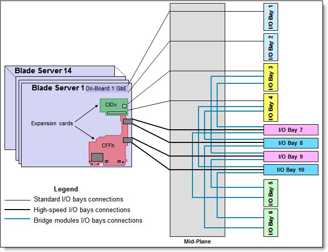
Figure 4. BladeCenter H I/O topology
The bays are:
- Bays 1 and 2 support only standard Ethernet-compatible I/O modules. These bays are routed internally to the onboard Ethernet controllers on the blades.
- Bays 3 and 4 can be used either for standard switch or pass-through modules (such as 8 Gb Fibre Channel or Gigabit Ethernet modules) or for bridge modules. These bays are routed internally to the CIOv connector on the blades.
- Bays 5 and 6 are dedicated for bridge modules only and do not directly connect to the blade bays. Bridge modules provide links to the I/O bays 7 - 10 and can be used as additional outputs for I/O modules in those bays. If I/O bays 3 and 4 are used for bridge modules, they are not directly connected to the blades, and bay 3 provides redundancy for bay 5, and bay 4 provides redundancy for bay 6.
- I/O bays 7 - 10 are used for high-speed switch modules such as the Virtual Fabric 10 Gb Switch Module or Cisco Nexus 4001I Switch Module. These bays are routed internally through midplane connectors to the ports on CFFh expansion cards (with HS23 blade, I/O bays 7 and 9 are routed to the integrated 10GbE ports on HS23 through LOM Interposer Card). I/O bays 7 - 10 can also be converted to the standard I/O bays with the Multi-Switch Interconnect Module (MSIM).
The I/O modules must be compatible with the I/O interfaces that are present in the blade servers. For example, when a Fibre Channel expansion card is installed in a blade server, I/O modules 3 and 4 must also be Fibre Channel-based (that is, an FC switch module), and vice versa. If you install FC switches in bays 3 and 4, then any expansion cards that are installed in all other blade servers in the same chassis must be Fibre Channel.
Table 4 shows the connections between the adapter slots in the compute nodes to the switch bays in the chassis.
Table 4. Adapter to I/O bay correspondence
| I/O adapter in each server |
Port on the adapter | Corresponding I/O module bay in the chassis |
| Onboard 1 Gb Ethernet | Port 1 | I/O bay 1 |
| Port 2 | I/O bay 2 | |
| Onboard 10 Gb Ethernet (HS23) | Port 1 | I/O bay 7 |
| Port 2 | I/O bay 9 | |
| CIOv adapter | Port 1 | I/O bay 3 |
| Port 2 | I/O bay 4 | |
| CFFh adapter | Port 1 | I/O bay 7 |
| Port 2 | I/O bay 9 | |
| Port 3 | I/O bay 8 | |
| Port 4 | I/O bay 10 |
Supported I/O modules
Tables 5 through 7 list the I/O modules that are supported by the BladeCenter H chassis and the corresponding I/O bay into which the I/O module can be installed.
| I/O module | Part number | Feature code (x-config / e-config) |
I/O bay number
|
|||||||||
|
1
|
2
|
3
|
4
|
5
|
6
|
7
|
8
|
9
|
10
|
|||
| Gigabit Ethernet | ||||||||||||
| Cisco Catalyst Switch Module 3012 | 43W4395 # | 5450 / 3174 | Y | Y | Y | Y | N | N | Y* | Y* | Y* | Y* |
| Cisco Catalyst Switch Module 3012 | 46C9272 # | A3FE / 3174 | Y | Y | Y | Y | N | N | Y* | Y* | Y* | Y* |
| Cisco Catalyst Switch Module 3110G | 41Y8523 # | 2989 / 3173 | Y | Y | Y | Y | N | N | Y* | Y* | Y* | Y* |
| Cisco Catalyst Switch Module 3110G | 00Y3254 # | A3FD / 3173 | Y | Y | Y | Y | N | N | Y* | Y* | Y* | Y* |
| Cisco Catalyst Switch Module 3110X | 41Y8522 # | 2988 / 3171 | Y | Y | Y | Y | N | N | Y* | Y* | Y* | Y* |
| Cisco Catalyst Switch Module 3110X | 00Y3250 # | A3FC / 3171 | Y | Y | Y | Y | N | N | Y* | Y* | Y* | Y* |
| 1/10Gb Uplink Ethernet Switch Module | 44W4404 | 1590 / 1590 | Y | Y | Y | Y | N | N | Y* | Y* | Y* | Y* |
| L2/3 Copper GbE Switch Module | 32R1860 | 1495 / 3212 | Y | Y | Y | Y | N | N | Y* | Y* | Y* | Y* |
| L2/3 Fiber GbE Switch Module | 32R1861 | 1496 / 3213 | Y | Y | Y | Y | N | N | Y* | Y* | Y* | Y* |
| L2-7 Gb Ethernet Switch Module | 32R1859 # | 1494 / 3211 | Y | Y | Y | Y | N | N | N | N | N | N |
| Server Connectivity Module | 39Y9324 | 1484 / 3220 | Y | Y | Y | Y | N | N | Y* | Y* | Y* | Y* |
| 10 Gb Ethernet | ||||||||||||
| Brocade Converged 10GbE Switch Module | 69Y1909 # | 7656 / none | N | N | N | N | N | N | Y† | Y† | ||
| Cisco Nexus 4001I Switch Module | 46M6071 # | 0072 / 2241 | N | N | N | N | N | N | Y | Y | Y | Y |
| Cisco Nexus 4001I Switch Module | 46C9270 # | A3FF / 2241 | N | N | N | N | N | N | Y | Y | Y | Y |
| Virtual Fabric 10Gb Switch Module | 46C7191 | 1639 / 3248 | N | N | N | N | N | N | Y | Y | Y | Y |
# Withdrawn, not available for ordering.
* Requires MSIM (39Y9314, feature code 1465) to be installed in high-speed I/O bays 7 and 8 or 9 and 10 or both when the module is used in bays 7 - 10.
† The Brocade Converged 10GbE Switch Module occupies two adjacent high-speed bays.
| I/O module | Part number | Feature code (x-config / e-config) |
I/O bay number
|
|||||||||
|
1
|
2
|
3
|
4
|
5
|
6
|
7
|
8
|
9
|
10
|
|||
| 4 Gb Fibre Channel | ||||||||||||
| Cisco 4Gb 20 port FC Switch Module | 39Y9280 # | 2983 / 3242 | N | N | Y | Y | N | N | N | Y* | N | Y* |
| Cisco 4Gb 20 port FC Switch Module | 44E5696 # | A3FH / 3242 | N | N | Y | Y | N | N | N | Y* | N | Y* |
| Cisco 4Gb 10 port FC Switch Module | 39Y9284 # | 2984 / 3241 | N | N | Y | Y | N | N | N | Y* | N | Y* |
| Cisco 4Gb 10 port FC Switch Module | 44E5692 # | A3FG / 3241 | N | N | Y | Y | N | N | N | Y* | N | Y* |
| 8 Gb Fibre Channel | ||||||||||||
| Brocade Enterprise 20-port 8Gb SAN Switch Module | 42C1828 | 5764 / none | N | N | Y | Y | N | N | N | Y* | N | Y* |
| Brocade 20-port 8Gb SAN Switch Module | 44X1920 | 5481 / 5869 | N | N | Y | Y | N | N | N | Y* | N | Y* |
| Brocade 10-port 8Gb SAN Switch Module | 44X1921 | 5483 / 5045 | N | N | Y | Y | N | N | N | Y* | N | Y* |
| QLogic 20-Port 8Gb SAN Switch Module | 44X1905 # | 5478 / 3284 | N | N | Y | Y | N | N | N | Y* | N | Y* |
| QLogic 20-Port 4/8Gb SAN Switch Module | 88Y6406 # | A24C / none | N | N | Y | Y | N | N | N | Y* | N | Y* |
| QLogic 8Gb Intelligent Pass-thru Module | 44X1907 | 5482 / 5449 | N | N | Y | Y | N | N | N | Y* | N | Y* |
| QLogic 4/8Gb Intelligent Pass-thru Module | 88Y6410 # | A24D / none | N | N | Y | Y | N | N | N | Y* | N | Y* |
| QLogic Virtual Fabric Extension Module | 46M6172 # | 4799 / none | N | N | Y | N | Y | N | N | N | N | N |
# Withdrawn, not available for ordering.
* Requires MSIM (39Y9314, feature code 1465) or MSIM-HT (44R5913, feature code 5491) to be installed in high-speed I/O bays 7 and 8 or 9 and 10 or both when the module is used in bay 8 or 10 or both.
| I/O module | Part number | Feature code (x-config / e-config) |
I/O bay number
|
|||||||||
|
1
|
2
|
3
|
4
|
5
|
6
|
7
|
8
|
9
|
10
|
|||
| SAS modules | ||||||||||||
| SAS Connectivity Module | 39Y9195 | 2980 / 3267 | N | N | Y | Y | N | N | N | N | N | N |
| InfiniBand modules | ||||||||||||
| Voltaire 40Gb InfiniBand Switch Module | 46M6005 # | 0057 / 3204 | N | N | N | N | N | N | Y† | Y† | ||
| Pass-through and interconnect modules | ||||||||||||
| Intelligent Copper Pass-thru Module | 44W4483 | 5452 / 5452 | Y | Y | Y | Y | N | N | Y* | Y* | Y* | Y* |
| 10Gb Ethernet Pass-thru Module | 46M6181 | 1641 / 5412 | N | N | N | N | N | N | Y | Y | Y | Y |
| Multi-Switch Interconnect Module | 39Y9314 | 1465 / 3239 | N | N | N | N | N | N | Y† | Y† | ||
# Withdrawn from marketing
† This module occupies two adjacent high-speed bays.
* Requires MSIM (39Y9314, feature code 1465) to be installed in high-speed I/O bays 7 and 8 or 9 and 10 or both when the module is used in bays 7 - 10.
For more information, see the following Lenovo Press Product Guides:
- Ethernet switches
https://lenovopress.com/servers/blades/networkmodule - Fibre Channel switches
https://lenovopress.com/servers/blades/storagemodule
Optical drives
The BladeCenter H supports one optical drive in the optical drive bay on the media tray. The optical drive and USB ports are available to any one blade server in the chassis. The drive and USB ports cannot be shared among multiple servers. The drive and USB ports can be used to install operating systems, update drivers, or to copy data to recordable media.
Table 8 lists the supported optical drives.
Table 8. Supported optical drives
| Part number | Feature code | Description | Maximum supported | Standard models where used |
| 46M0901 | 4161 | UltraSlim Enhanced SATA DVD-ROM | 1 | - |
| 46M0902 | 4163 | UltraSlim Enhanced SATA Multi-Burner | 1 | 94x, 95x, 96x |
UltraSlim Enhanced SATA DVD-ROM (part number 46M0901) supports the following media and speeds for reading:
- CD-ROM 24X
- CD-R 24X
- CD-RW 24X
- DVD-ROM (4.7 GB) 8X
- DVD-ROM (dual layer, 8.5 GB) 8X
- DVD-R (4.7 GB) 8X
- DVD-R (dual layer, 8.5 GB) 8X
- DVD+R (4.7 GB) 8X
- DVD+R (dual layer, 8.5 GB) 8X
- DVD-RW (4.7 GB) 8X
- DVD+RW (4.7 GB) 8X
- DVD-RAM (4.7 GB) 5X
IBM UltraSlim Enhanced SATA Multi-Burner (46M0902) supports the same media and speeds for reading as DVD-ROM (46M0901). This drive also supports the following media and speeds for writing:
- CD-R 24X
- CD-RW 4X
- High Speed CD-RW 10X
- Ultra Speed CD-RW 24X
- Ultra Speed Plus CD-RW 24X
- DVD-R (4.7 GB) 8X
- DVD-R (dual layer, 8.5 GB) 6X
- DVD+R (4.7 GB) 8X
- DVD+R (dual layer, 8.5 GB) 6X
- DVD-RW (4.7 GB) 6X
- DVD+RW (4.7 GB) 8X
- DVD-RAM (4.7 GB) 5X
Remote management
Remote management functionality is provided by the Advanced Management Module (AMM). The AMM is a hot-swap module that you use to configure and manage all installed BladeCenter components. The AMM provides system management functions and KVM multiplexing for all blade servers in the BladeCenter unit that support KVM. It controls a serial port for remote connection, the external keyboard, mouse, and video connections for use by a local console, and a 10/100 Mbps Ethernet remote management connection.
The BladeCenter H chassis comes standard with at least one AMM, and it supports up to two redundant hot-swap AMMs in an active/standby configuration. Table 9 shows the AMM ordering information.
Table 9. Advanced Management Module
| Part number | Feature code | Description |
| 2019A1X | 1604 | Advanced Management Module for BladeCenter |
Figure 5 shows the Advanced Management Module.
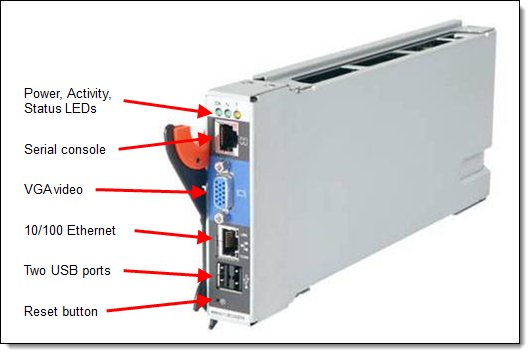
Figure 5. Advanced Management Module
The following tasks can be performed with AMM:
- Defining the login IDs and passwords
- Configuring security settings, such as data encryption and user account security
- Selecting recipients for alert notification of specific events
- Monitoring the status of the BladeCenter unit, blade servers, and other BladeCenter components:
- Event log
- LEDs
- Hardware and firmware VPD
- Fan speeds
- Temperatures
- Power usage
- Discovering other BladeCenter units in the network and enabling access to them through their management-module web interfaces
- Controlling the BladeCenter unit, blade servers, and other BladeCenter components:
- Power on/off
- Firmware update
- Configuration settings
- Serial over LAN
- Configuring power management for the BladeCenter unit
- Accessing the I/O modules to configure them
- Changing the startup sequence in a blade server
- Setting the date and time
- Using a remote console for the blade servers
- Mounting remote virtual media for the blade servers
- Changing ownership of the keyboard, video, and mouse
- Changing ownership of the removable-media drives and USB ports (The removable-media drives in the BladeCenter unit are viewed as USB devices by the blade server operating system.)
- Using IBM Fabric Manager functions
- Using Service Advisor functions to autonomously inform Lenovo Support about any critical events that happen
AMM supports the following management methods:
- Web-based interface with SSL support
- CLI through Telnet/SSH
- SMASH Command Line Protocol
- SNMP
For more information about AMM, see the following product documentation:
- BladeCenter Advanced Management Module Installation Guide, found at:
http://ibm.com/support/entry/portal/docdisplay?lndocid=MIGR-5073392 - BladeCenter Advanced Management Module User's Guide, found at:
http://ibm.com/support/entry/portal/docdisplay?lndocid=MIGR-5073887 - Advanced Management Module Command Line Interface Reference Guide, found at:
http://ibm.com/support/entry/portal/docdisplay?lndocid=MIGR-54667
Serial console
The BladeCenter H has a serial port breakout connector to provide a direct serial connection to installed blades (for those blades with the functionality) with the Serial Port Breakout Cable. This cable connects directly to the port on the rear of the BladeCenter H, providing 14 serial connections for terminal access, one to each supported blade server.
Important: HS23, HS23E, HX5, PS700, PS701, PS702, PS703, and PS704 blades do not support direct serial connections.
Table 10 contain the ordering information for the Serial Port Breakout Cable.
Table 10. Serial Port Breakout Cable ordering part number and feature code
| Part number | Feature code | Description |
| 40K9605 | 4811 | Serial Port Breakout Cable for BladeCenter |
Power modules
The BladeCenter H supports up to four hot-swap redundant 2980 W AC power modules. Power module redundancy is provided within a pair (power modules 1 and 2; power modules 3 and 4). Older models might contain 2900 W power modules. To determine whether you need 2980 W power supplies, consult the "Supported servers" section.
The power modules in bays 1 and 2 are used to power blade servers in blade bays 1 - 7 and I/O modules in I/O module bays 1 - 4 and 7 - 10. The power modules are needed in power module bays 3 and 4 if you install blade servers in blade bays 8 - 14, or if you install I/O modules in any of I/O module bays 5 - 10.
Two power modules are standard in model 5Tx, and a maximum of four power modules are supported. Models 93x, 94x, and 95x come standard with four power supplies. Table 11 shows the ordering information for power modules (the part number contains two power modules).
Table 11. Power modules ordering part number and feature code
| Part number | Feature code | Description |
| 68Y6601 | 2143 | BladeCenter H 2980 W AC Power Modules (2) with Fan Packs |
No power cables are shipped with either the BladeCenter H chassis or the power module option. Order them separately (two power cables per one chassis). Table 12 contains the ordering information for power cables.
Table 12. Power cable ordering part numbers and feature codes
| Part number | Feature code | Description |
| 25R5783 | 6270 | 4.3 m 208 V Double 30A NEMA L6-30P |
| 25R5784 | 6271 | 4.3 m 230 V Dual 32A IEC 309 P+N+G/16A IEC 320-C20 |
| 25R5785 | 6226 | 2.8 m 200-240 V Triple 16A IEC 320-C20 |
| 25R5811 | 6273 | 4.3 m 220 V Double 30A KSC 8305 (for South Korea) |
| 25R5812 | 6272 | 4.3 m 230 V Dual 32A AS/NZS 3112/16A IEC 320-C20 (for Australia/NZ) |
Cooling modules
The BladeCenter H comes with two hot-swap blowers for cooling redundancy. There are two types of blower modules that are available:
- Standard blowers: Standard in model 8852-4Sx and older models.
- Enhanced Cooling Module (also referred to as the enhanced blower): Standard in models 5Tx, 94x, 95x, 96x, and some older models (4Tx, 91x, 92x, 93x). Optional in other older BladeCenter H models.
To determine whether you need Enhanced Cooling modules, consult the "Supported servers" section.
Table 13 lists the optional enhanced blowers that can be ordered for the BladeCenter H chassis (the part number contains two blowers).
Table 13. Enhanced cooling modules ordering part number and feature code
| Part number | Feature code | Description |
| 68Y6650 | 0724 | BladeCenter H Enhanced Cooling Modules (two blowers) |
Physical and electrical specifications
Dimensions and weight (approximate):
- Height: 400 mm (15.8 in.)
- Width: 483 mm (19.0 in)
- Depth: 711 mm (28.0 in)
- Weight:
- Minimum configuration: 41 kg (90 lb)
- Maximum configuration: 159 kg (350 lb)
Supported environment:
- Temperature and humidity:
- 10.0 - 35.0 degrees C (50 - 95 degrees F) at 0 - 914 m (0 - 3,000 ft)
- 10.0 - 32.0 degrees C (50 - 90 degrees F) at 914 - 2,133 m (3,000 - 7,000 ft)
- Relative humidity: 8% - 80%
- Maximum altitude: 2,133 m (7,000 ft)
- Supported electrical input:
- 200 - 240 (nominal) V ac; 50 Hz or 60 Hz; 37 A (X2)/48 A maximum
- Input kilovolt-amperes (kVA) (approximately):
- Minimum configuration: 0.3 kVA
- Maximum configuration: 9.6 kVA
- BTU output:
- Minimum configuration: 1024 Btu/hr (300 VA)
- Maximum configuration: 32409 Btu/hr (9600 VA)
- Acoustical:
- Declared sound power level: 7.5 bels
Warranty options
The system has a three-year warranty with 24x7 standard call center support and 9x5 Next Business Day onsite coverage. Also available are Lenovo Services warranty maintenance upgrades and post-warranty maintenance agreements, with a well-defined scope of services, including service hours, response time, term of service, and service agreement terms and conditions.
Lenovo warranty service upgrade offerings are region-specific. Not all warranty service upgrades are available in every region. For more information about Lenovo warranty service upgrade offerings that are available in your region, go to the Data Center Advisor and Configurator website http://dcsc.lenovo.com, then do the following:
- In the Customize a Model box in the middle of the page, select the Services option in the Customization Option dropdown menu
- Enter in the machine type & model of the system
- From the search results, you can click either Deployment Services or Support Services to view the offerings
The following table explains warranty service definitions in more detail.
| Term | Description |
|---|---|
| On-site service | A service technician will arrive at the client’s location for equipment service. |
| 24x7x2 hour | A service technician is scheduled to arrive at the client’s location within two hours after remote problem determination is completed. Lenovo provides service around the clock, every day, including Lenovo holidays. |
| 24x7x4 hour | A service technician is scheduled to arrive at the client’s location within four hours after remote problem determination is completed. Lenovo provides service around the clock, every day, including Lenovo holidays. |
| 9x5x4 hour | A service technician is scheduled to arrive at the client’s location within four business hours after remote problem determination is completed. Lenovo provides service 8:00 am - 5:00 pm in the client's local time zone, Monday-Friday, excluding Lenovo holidays. For example, if a customer reports an incident at 3:00 pm on Friday, the technician will arrive by 10:00 am the following Monday. |
| 9x5 next business day | A service technician is scheduled to arrive at the client’s location on the business day after remote problem determination is completed. Lenovo provides service 8:00 am - 5:00 pm in the client's local time zone, Monday - Friday, excluding Lenovo holidays. Calls received after 4:00 pm local time require an extra business day for service dispatch. Next business day service is not guaranteed. |
| Committed Repair | Problems receive priority handling so that repairs are completed within the committed time of 6, 8, or 24 hours. Lenovo provides service 24 hours/day, every day, including Lenovo holidays. |
The following Lenovo warranty service upgrades are available:
- Warranty and maintenance service upgrades:
- Three, four, or five years of 9x5 or 24x7 service coverage
- Onsite response from next business day to 2 or 4 hours
- Committed repair service
- Warranty extension of up to 5 years
- Post warranty extensions
- Committed Repair Service
Committed Repair Services enhances the level of Warranty Service Upgrade or Post Warranty/Maintenance Service offering associated with the selected systems. Offerings vary and are available in select countries.
- Priority handling to meet defined time frames to restore the failing machine to good working condition
- Committed repair service levels are measured within the following coverage hours:
- 24x7x6: Service performed 24 hours per day, 7 days per week, within 6 hours
- 24x7x8: Service performed 24 hours per day, 7 days per week, within 8 hours
- 24x7x24: Service performed 24 hours per day, 7 days per week, within 24 hours
- Hard Disk Drive Retention
Lenovo’s Hard Disk Drive Retention (HDDR) service is a multi-drive hard drive retention offering that ensures your data is always under your control, regardless of the number of hard drives that are installed in your Lenovo server. In the unlikely event of a hard drive failure, you retain possession of your hard drive while Lenovo replaces the failed drive part. Your data stays safely on your premises, in your hands. The Hard Drive Retention service can be purchased in convenient bundles with our warranty upgrades and extensions.
- Microcode Support
Keeping microcode current helps prevent hardware failures and security exposure. There are two levels of service: analysis of the installed base and analysis and update where required. Offerings vary by region and can be bundled with other warranty upgrades and extensions.
- Remote Technical Support Services (RTS)
RTS provides comprehensive technical call center support for covered servers, storage, operating systems, and applications. Providing a single source for support of hardware and software issues, RTS can reduce problem resolution time, decreasing the cost to address technical problems and increasing uptime. Offerings are available for Windows, Linux, IBM Systems Director, VMware, Microsoft business applications, and Lenovo System x storage devices, and IBM OEM storage devices.
Regulatory compliance
The chassis conforms to the following regulations:
- FCC - Verified to comply with Part 15 of the FCC Rules, Class A
- Canada ICES-003, issue 4, Class A
- UL/IEC 60950-1(11)
- CAN C22.2 No. 60950-1-03
- NOM-019(11)
- Japan VCCI, Class A
- Australia/New Zealand AS/NZS CISPR 22:2008, Class A
- IEC-60950-1 (CB Certificate and CB Test Report)
- Russia/GOST ME01, IEC-60950-1
- CE Mark (EN55022 Class A, EN60950, and EN55024)
- CISPR 22, Class A
- TUV-GS (EN60950-1, EK1-ITB)
External disk storage systems
Table 15 lists the external storage systems that are supported by the blade servers that are installed in the BladeCenter H chassis and can be ordered through the System x® sales channel. The servers might support other disk systems that are not listed in this table. For more information, see the IBM System Storage® Interoperation Center at http://www.ibm.com/systems/support/storage/ssic.
Table 15. External disk storage systems
| Part number | Description |
| IBM Storwize® V3700 | |
| 20722LC | IBM Storwize V3700 LFF Dual Control Enclosure |
| 20722SC | IBM Storwize V3700 SFF Dual Control Enclosure |
| IBM System Storage DS3500 | |
| 1746A2D | IBM System Storage DS3512 Express Dual Controller Storage System |
| 1746A2S | IBM System Storage DS3512 Express Single Controller Storage System |
| 1746A4D | IBM System Storage DS3524 Express Dual Controller Storage System |
| 1746A4S | IBM System Storage DS3524 Express Single Controller Storage System |
| IBM System Storage DS3950 (5020) | |
| 181494H | IBM System Storage DS3950 Model 94 |
| 181498H | IBM System Storage DS3950 Model 98 |
For more information, see the list of Lenovo Press Product Guides in the IBM Storage category at
https://lenovopress.com/storage/san/ibm
External backup units
The blade servers that are installed in the BladeCenter H chassis support the external backup attachment options that are listed in the following table.
| Part number | Description |
|---|---|
| External tape expansion enclosures for internal tape drives | |
| 87651UX | 1U Tape Drive Enclosure |
| 8767HHX | Half High Tape Drive Enclosure |
| 87651NX | 1U Tape Drive Enclosure (with NEMA 5-15P Line Cord) |
| 8767HNX | Half High Tape Drive Enclosure (with NEMA 5-15P Line Cord) |
| Tape enclosure adapters (with cables) | |
| 44E8869 | USB Enclosure Adapter Kit |
| 40K2599 | SAS Enclosure Adapter Kit |
| Internal backup drives that are supported by external tape enclosures | |
| 46C5399 | DDS Generation 5 USB Tape Drive |
| 39M5636 | DDS Generation 6 USB Tape Drive |
| 43W8478 | Half High LTO Gen 3 SAS Tape Drive |
| 44E8895 | Half High LTO Gen 4 SAS Tape Drive |
| 49Y9898 | Half High LTO Gen 5 Internal SAS Tape Drive |
| External backup units* | |
| 3628L3X | Half High LTO Gen 3 External SAS Tape Drive (with US power cord) |
| 3628L4X | Half High LTO Gen 4 External SAS Tape Drive (with US power cord) |
| 3628L5X | Half High LTO Gen 5 External SAS Tape Drive (with US power cord) |
| 3628N3X | Half High LTO Gen 3 External SAS Tape Drive (without power cord) |
| 3628N4X | Half High LTO Gen 4 External SAS Tape Drive (without power cord) |
| 3628N5X | Half High LTO Gen 5 External SAS Tape Drive (without power cord) |
| 3580S3V | System Storage TS2230 Tape Drive Express Model H3V |
| 3580S4V | System Storage TS2240 Tape Drive Express Model H4V |
| 3580S5E | System Storage TS2250 Tape Drive Express Model H5S |
| 3580S5X | System Storage TS2350 Tape Drive Express Model S53 |
| 3572S4R | TS2900 Tape Library with LTO4 HH SAS drive & rack mount kit |
| 3572S5R | TS2900 Tape Library with LTO5 HH SAS drive & rack mount kit |
| 35732UL | TS3100 Tape Library Model L2U Driveless |
| 35734UL | TS3200 Tape Library Model L4U Driveless |
| 46X2682† | LTO Ultrium 5 Fibre Channel Drive |
| 46X2683† | LTO Ultrium 5 SAS Drive Sled |
| 46X2684† | LTO Ultrium 5 Half High Fibre Drive Sled |
| 46X2685† | LTO Ultrium 5 Half High SAS Drive Sled |
| 46X6912† | LTO Ultrium 4 Half High Fibre Channel Drive Sled |
| 46X7117† | LTO Ultrium 4 Half High SAS DriveV2 Sled |
| 46X7122† | LTO Ultrium 3 Half High SAS DriveV2 Sled |
* Note: The external tape drives listed can be ordered through the System x sales channel. The server might support other tape drives that are not listed in this table. For more information, see the IBM System Storage Interoperability Center.
† Note: These part numbers are the tape drives options for 35732UL and 35734UL.
For more information, see the list of Lenovo Press Product Guides in the Backup units category at
https://lenovopress.com/storage/tape/drives
Top-of-rack Ethernet switches
The following table lists the Ethernet LAN switches that are offered by Lenovo.
| Part number | Description |
|---|---|
| 1 Gb Ethernet Rack switches | |
| 7Y810011WW | Lenovo ThinkSystem NE0152T RackSwitch (Rear to Front) |
| 7Z320O11WW | Lenovo ThinkSystem NE0152TO RackSwitch (Rear to Front, ONIE) |
| 7159BAX | Lenovo RackSwitch G7028 (Rear to Front) |
| 7159CAX | Lenovo RackSwitch G7052 (Rear to Front) |
| 7159G52 | Lenovo RackSwitch G8052 (Rear to Front) |
| 7165H1X | Juniper EX2300-C PoE Switch |
| 7165H2X | Juniper EX2300-24p PoE Switch |
| 1 Gb Ethernet Campus switches | |
| 7Z340011WW | Lenovo CE0128TB Switch (3-Year Warranty) |
| 7Z360011WW | Lenovo CE0128TB Switch (Limited Lifetime Warranty) |
| 7Z340012WW | Lenovo CE0128PB Switch (3-Year Warranty) |
| 7Z360012WW | Lenovo CE0128PB Switch (Limited Lifetime Warranty) |
| 7Z350021WW | Lenovo CE0152TB Switch (3-Year Warranty) |
| 7Z370021WW | Lenovo CE0152TB Switch (Limited Lifetime Warranty) |
| 7Z350022WW | Lenovo CE0152PB Switch (3-Year Warranty) |
| 7Z370022WW | Lenovo CE0152PB Switch (Limited Lifetime Warranty) |
| 10 Gb Ethernet switches | |
| 7159A1X | Lenovo ThinkSystem NE1032 RackSwitch (Rear to Front) |
| 7159B1X | Lenovo ThinkSystem NE1032T RackSwitch (Rear to Front) |
| 7Z330O11WW | Lenovo ThinkSystem NE1064TO RackSwitch (Rear to Front, ONIE) |
| 7159C1X | Lenovo ThinkSystem NE1072T RackSwitch (Rear to Front) |
| 7159CRW | Lenovo RackSwitch G8272 (Rear to Front) |
| 7159GR6 | Lenovo RackSwitch G8296 (Rear to Front) |
| 7159BR6 | Lenovo RackSwitch G8124E (Rear to Front) |
| 25 Gb Ethernet switches | |
| 7159E1X | Lenovo ThinkSystem NE2572 RackSwitch (Rear to Front) |
| 7Z210O21WW | Lenovo ThinkSystem NE2572O RackSwitch (Rear to Front, ONIE) |
| 7Z330O21WW | Lenovo ThinkSystem NE2580O RackSwitch (Rear to Front, ONIE) |
| 100 Gb Ethernet switches | |
| 7159D1X | Lenovo ThinkSystem NE10032 RackSwitch (Rear to Front) |
| 7Z210O11WW | Lenovo ThinkSystem NE10032O RackSwitch (Rear to Front, ONIE) |
For more information, see the list of Product Guides in the following switch categories:
- 1 Gb Ethernet switches: http://lenovopress.com/networking/tor/1gb?rt=product-guide
- 10 Gb Ethernet switches: http://lenovopress.com/networking/tor/10gb?rt=product-guide
- 25 Gb Ethernet switches: http://lenovopress.com/networking/tor/25gb?rt=product-guide
- 40 Gb Ethernet switches: http://lenovopress.com/networking/tor/40gb?rt=product-guide
- 100 Gb Ethernet switches: https://lenovopress.com/networking/tor/100Gb?rt=product-guide
Fibre Channel SAN switches
Lenovo offers the ThinkSystem DB Series of Fibre Channel SAN switches for high-performance storage expansion. See the DB Series product guides for models and configuration options:
- ThinkSystem DB Series SAN Switches:
https://lenovopress.com/storage/switches/rack#rt=product-guide
Power distribution units
Power planning for an BladeCenter H is strongly recommended. For details about possible power configurations, see the BladeCenter Power Guide, found at http://ibm.com/support/entry/portal/docdisplay?lndocid=LNVO-POWINF
The chassis supports attachments to the power distribution units (PDUs) that are listed in the following table.
Table 18. Power distribution units
| Part number | Description |
| Switched and monitored PDUs | |
| 46M4002 | 1U 9 C19/3 C13 Active Energy Manager DPI PDU |
| 46M4003 | 1U 9 C19/3 C13 Active Energy Manager 60A 3 Phase PDU |
| 46M4167 | 1U 9 C19/3 C13 Switched and Monitored 30A 3 Phase PDU |
| 46M4134 | 0U 12 C19/12 C13 Switched and Monitored 50A 3 Phase PDU |
| 46M4140 | 0U 12 C19/12 C13 50A 3 Phase PDU |
| Enterprise PDUs | |
| 71762MX | Ultra Density Enterprise PDU C19 PDU+ (WW) |
| 71762NX | Ultra Density Enterprise PDU C19 PDU (WW) |
| 71763MU | Ultra Density Enterprise PDU C19 3 phase 60A PDU+ (NA) |
| 71763NU | Ultra Density Enterprise PDU C19 3 phase 60A PDU (NA) |
| 39Y8923 | DPI 60A Three Phase C19 Enterprise PDU with IEC309 3P+G (208 V) fixed power cord |
| 39Y8948 | DPI Single Phase C19 Enterprise PDU without power cord |
| Front-end PDUs | |
| 39Y8934 | DPI 32amp/250V Front-end PDU with IEC 309 2P+Gnd connector |
| 39Y8938 | 30amp/125V Front-end PDU with NEMA L5-30P connector |
| 39Y8939 | 30amp/250V Front-end PDU with NEMA L6-30P connector |
| 39Y8940 | 60amp/250V Front-end PDU with IEC 309 60A 2P+N+Gnd connector |
| 0U Basic PDUs | |
| 46M4140 | 0U 12 C19/12 C13 60A 3 Phase PDU |
| 46M4143 | 0U 12 C19/12 C13 32A 3 Phase PDU |
For more information, see the list of Lenovo Press Product Guides in the PDU category at:
https://lenovopress.com/servers/options/pdu
Uninterruptible power supply units
The BladeCenter H chassis supports attachments to the uninterruptible power supply units listed in the following table.
Table 19. Uninterruptible power supply units
| Part number | Description |
| 55945KX | RT5kVA 3U Rack or Tower UPS (200-240VAC) |
| 55946KX | RT6kVA 3U Rack or Tower UPS (200-240VAC) |
| 55948KX | RT8kVA 6U Rack or Tower UPS (200-240VAC) |
| 55949KX | RT11kVA 6U Rack or Tower UPS (200-240VAC) |
| 55948PX | RT8kVA 6U 3:1 Phase Rack or Tower UPS (380-415VAC) |
| 55949PX | RT11kVA 6U 3:1 Phase Rack or Tower UPS (380-415VAC) |
For more information, see the list of Lenovo Press Product Guides in the UPS category at
https://lenovopress.com/servers/options/ups
Rack cabinets
The BladeCenter H chassis is supported in the rack cabinets that are listed in the following table.
Table 20. Rack cabinets
| Part number | Description |
| 201886X | 11U Office Enablement Kit |
| 93072PX | 25U Static S2 Standard Rack |
| 93072RX | 25U Standard Rack |
| 93074RX | 42U Standard Rack |
| 93074XX | 42U Standard Rack Extension |
| 93084EX | 42U Enterprise Expansion Rack |
| 93084PX | 42U Enterprise Rack |
| 93604EX | 42U 1200mm Deep Dynamic Expansion Rack |
| 93604PX | 42U 1200mm Deep Dynamic Rack |
| 93614EX | 42U 1200mm Deep Static Expansion Rack |
| 93614PX | 42U 1200mm Deep Static Rack |
| 93624EX | 47U 1200mm Deep Static Expansion Rack |
| 93624PX | 47U 1200mm Deep Static Rack |
| 93634CX | PureFlex™ System 42U Rack |
| 93634DX | PureFlex System 42U Expansion Rack |
| 93634EX | 42U 1100mm Dynamic Expansion Rack |
| 93634PX | 42U 1100mm Dynamic Rack |
| 99564RX | S2 42U Dynamic Standard Rack |
| 99564XX | S2 42U Dynamic Standard Expansion Rack |
For more information, see the list of Lenovo Press Product Guides in the Rack cabinets and options category:
https://lenovopress.com/servers/options/racks
Rack options
The BladeCenter H chassis supports the rack console switches and monitor kits that are listed in the following table.
Table 21. Rack options
| Part number | Description |
| Monitor kits and keyboard trays | |
| 172317X | 1U 17in Flat Panel Console Kit |
| 172319X | 1U 19in Flat Panel Console Kit |
| Console switches | |
| 1754D2X | Global 4x2x32 Console Manager (GCM32) |
| 1754D1X | Global 2x2x16 Console Manager (GCM16) |
| 1754A2X | Local 2x16 Console Manager (LCM16) |
| 1754A1X | Local 1x8 Console Manager (LCM8) |
| Rack conversion options | |
| 46M5382 | Serial Conversion Option (SCO) |
| 46M5383 | Virtual Media Conversion Option Gen2 (VCO2) |
| 39M2895 | USB Conversion Option (UCO) |
For more information, see the list of Lenovo Press Product Guides in the KVM Switches & Consoles category
https://lenovopress.com/servers/options/kvm
Lenovo Financial Services
Lenovo Financial Services reinforces Lenovo’s commitment to deliver pioneering products and services that are recognized for their quality, excellence, and trustworthiness. Lenovo Financial Services offers financing solutions and services that complement your technology solution anywhere in the world.
We are dedicated to delivering a positive finance experience for customers like you who want to maximize your purchase power by obtaining the technology you need today, protect against technology obsolescence, and preserve your capital for other uses.
We work with businesses, non-profit organizations, governments and educational institutions to finance their entire technology solution. We focus on making it easy to do business with us. Our highly experienced team of finance professionals operates in a work culture that emphasizes the importance of providing outstanding customer service. Our systems, processes and flexible policies support our goal of providing customers with a positive experience.
We finance your entire solution. Unlike others, we allow you to bundle everything you need from hardware and software to service contracts, installation costs, training fees, and sales tax. If you decide weeks or months later to add to your solution, we can consolidate everything into a single invoice.
Our Premier Client services provide large accounts with special handling services to ensure these complex transactions are serviced properly. As a premier client, you have a dedicated finance specialist who manages your account through its life, from first invoice through asset return or purchase. This specialist develops an in-depth understanding of your invoice and payment requirements. For you, this dedication provides a high-quality, easy, and positive financing experience.
For your region-specific offers, please ask your Lenovo sales representative or your technology provider about the use of Lenovo Financial Services. For more information, see the following Lenovo website:
https://www.lenovo.com/us/en/landingpage/lenovo-financial-services/
Trademarks
Lenovo and the Lenovo logo are trademarks or registered trademarks of Lenovo in the United States, other countries, or both. A current list of Lenovo trademarks is available on the Web at https://www.lenovo.com/us/en/legal/copytrade/.
The following terms are trademarks of Lenovo in the United States, other countries, or both:
Lenovo®
BladeCenter Interoperability Guide
BladeCenter Open Fabric
BladeCenter®
Lenovo Services
MAX5
RackSwitch
ServerProven®
System x®
ThinkSystem®
The following terms are trademarks of other companies:
Intel® and Xeon® are trademarks of Intel Corporation or its subsidiaries.
Linux® is the trademark of Linus Torvalds in the U.S. and other countries.
Microsoft® and Windows® are trademarks of Microsoft Corporation in the United States, other countries, or both.
Other company, product, or service names may be trademarks or service marks of others.


