

Top
Abstract
Lenovo BladeCenter® remains an innovative solution to running business solutions. BladeCenter builds on the Lenovo commitment to integrating server, storage, and networking functionality with technology exchange and heterogeneous management. BladeCenter offers the ease, density, availability, affordability, and scalability that are central to the blade technology promise.
BladeCenter S combines the power of blade servers with integrated storage, all in an easy-to-use package that is designed specifically for the office and distributed enterprise environment. The BladeCenter S chassis can hold up to six blade servers, and up to 12 hot-swap 3.5-inch SAS or SATA disk drives in just 7U of rack space.
Withdrawn from marketing: The BladeCenter S chassis is withdrawn from marketing.
Introduction
Lenovo BladeCenter® remains an innovative solution to running business solutions. BladeCenter builds on the Lenovo commitment to integrating server, storage, and networking functionality with technology exchange and heterogeneous management. BladeCenter offers the ease, density, availability, affordability, and scalability that are central to the blade technology promise.
BladeCenter S combines the power of blade servers with integrated storage, all in an easy-to-use package that is designed specifically for the office and distributed enterprise environment. The BladeCenter S chassis can hold up to six blade servers, and up to 12 hot-swap 3.5-inch SAS or SATA disk drives in just 7U of rack space.
The BladeCenter S is shown in Figure 1.
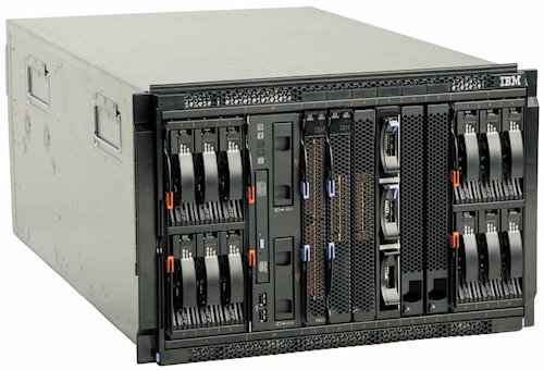
Figure 1. The BladeCenter S
Did you know?
Unlike the BladeCenter E and BladeCenter H chassis, the BladeCenter S is designed to operate on either 110 V or 220 V power. It is also designed to run in an office environment with the BladeCenter S Office Enablement Kit. The combination of these features means that the BladeCenter S is ideal for customers with a distributed IT infrastructure where there is no dedicated computer room.
Key features
This section lists the key features of BladeCenter S chassis.
Performance
The BladeCenter S chassis offers numerous features to boost performance and reduce costs:
- Support for the latest generation of BladeCenter blades, helping to provide performance and investment protection.
- Blade servers communicate directly to switch modules inside the BladeCenter chassis via redundant midplane links to help increase the speed and efficiency of data transfers across blade servers and networks.
- A blade server that is installed in a BladeCenter S has access to as many as four internal switches, which means that up to eight I/O ports can be enabled from each server that is installed in the chassis.
Flexibility and scalability
The BladeCenter S chassis can grow with your application requirements with these features:
- BladeCenter Virtual Fabric delivers a flexible, open, and connected infrastructure to help optimize application performance. BladeCenter supports many fabrics, including Ethernet, Fibre Channel, InfiniBand, iSCSI, and SAS.
- Support for both x86 servers and Power Systems™ servers in a single chassis.
- BladeCenter S can be used in either 220 V or 110 V power environments. Couple this flexibility with the office-friendly Office Enablement Kit and BladeCenter S fits well in a standard back-office environment, as well as in a data center.
- The two Disk Storage Modules support up to 24 TB of share storage that is integrated into the chassis, providing flexibility and convenience in your application design and data placement.
- The Disk Storage Modules are available either with 3.5-inch drive bays or with 2.5-inch drive bays
- A complete integrated offering is provided with space for servers, networking, and shared storage - all in one 7U modular design enclosure.
- Available Serial Pass-thru Module provides a dedicated serial port to every blade server in the chassis for the applications that need it.
- The BladeCenter server form factor has remained the same since 2002, which means that most servers that are designed for BladeCenter are supported in all BladeCenter chassis. This continuity maximizes flexibility and manageability.
Manageability and security
Powerful systems management features simplify local and remote management of the BladeCenter S chassis:
- The high degree of integration in the various BladeCenter chassis reduces the need for server components, replacing numerous fans, keyboard/video/mouse (KVM) and Ethernet cables, power supplies, external switches, and other components.
- Each BladeCenter chassis includes an Advanced Management Module (AMM). The AMM boosts administrator productivity and reduces skill level requirements, which can help reduce costs, improve overall productivity, and make administration easier.
- Unlike traditional servers and some competitive blades with a myriad of separate management tools, the AMM provides a single point of control for the solution and supports many industry-standard, open protocols.
- The AMM provides systems management capabilities, including web-based out-of-band control; virtual media support; Windows “blue screen” error capture; Lightweight Directory Access Protocol (LDAP) and Secure Sockets Layer (SSL) support; and remote redirection of video, text, keyboard, and mouse for the chassis and the components that are installed in the chassis.
- IBM Systems Director remains a powerful and intelligent solution to manage BladeCenter systems with rack mount and tower servers. Systems Director exploits the hardware’s capabilities by surfacing pertinent information about your blade server. The easy-to-use wizards provide step-by-step instructions and offer automated deployment capabilities.
- IBM Fabric Manager simplifies the deployment of infrastructure connections by managing network and storage address assignments.
- Integrated industry-standard Unified Extensible Firmware Interface (UEFI) in supported servers enables improved setup, configuration, and updates, and simplifies error handling.
- Integrated Trusted Platform Module (TPM) 1.2 in supported servers enables advanced cryptographic functionality, such as digital signatures and remote attestation.
Availability and serviceability
The BladeCenter S chassis provides many features to simplify serviceability and increase system uptime:
- BladeCenter reduces the number of parts that are required to run the system. Sharing fans, power supplies, systems management, and ports means fewer parts to buy and maintain, and fewer components that can fail and cause downtime.
- Hot-swap components, such as the server, switches, power supplies, and blowers, ensures maximum uptime.
- Redundant components, such as blowers and power supplies, and available RAID support for the drives in the Disk Storage Modules (DSMs) ensures that systems can remain available even during hardware failures.
- The Predictive Failure Analysis (PFA) detects when system components (processors, memory, and hard disk drives) operate outside of standard thresholds and generates proactive alerts in advance of a possible failure, therefore increasing uptime.
- Dual independent power and signal connectors to the BladeCenter chassis midplane provide fault tolerance to increase uptime.
- Tool-less cover removal provides easy access to upgrades and serviceable parts, such as CPU, memory, and adapters.
- A standard three-year (parts and labor) limited on-site warranty affords customers peace of mind and greater potential investment protection.
Energy efficiency
The BladeCenter S chassis has an energy-efficient design with features that include the following functions:
- The BladeCenter family features the industry’s most energy-efficient design. The various BladeCenter chassis use ultra-high efficiency power supplies. BladeCenter power modules are up to 91% efficient at converting power from ac wall current to the dc power that is used inside servers. This efficiency helps save money because more of the power input for which the customer is paying is used for processing, rather than released into the data center as wasted heat.
- Environmentally tuned blower/fan modules in the chassis adjust to compensate for changing thermal characteristics. At the lower speeds, they draw less power and suffer less wear. Equally important in a crowded data center, temperature-controlled blowers and fans produce less ambient noise in the data center than if they ran constantly at full speed.
- Low-voltage Intel Xeon processors and low-voltage dual inline memory modules (DIMMs) in supported servers draw less energy to satisfy demands of power and thermally constrained data centers and telecommunication environments.
- IBM Systems Director Active Energy Manager™ provides advanced power management features with actual real-time energy monitoring, reporting, and capping features.
Locations of key components
Figure 2 shows the front of the BladeCenter S chassis.
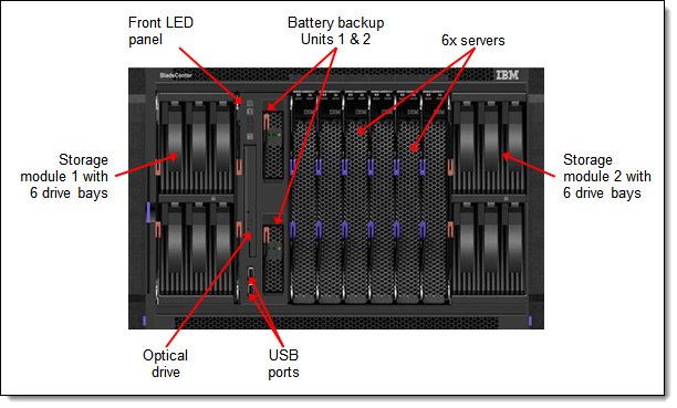
Figure 2. Front of the BladeCenter S chassis
Figure 3 shows the rear of the BladeCenter S chassis.
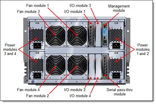
Figure 3. Rear of the BladeCenter S chassis
Standard specifications
The following table lists the standard specifications.
Table 1. Standard specifications
| Components | Specification |
| Machine type | System x sales channel: 8886 Power Systems sales channel: 7779 |
| Form factor | 7U rack-mounted unit. |
| Maximum number of servers supported | Up to six server blades in six bays. Supports double-wide servers or servers with expansion blades. |
| Systems supported | All BladeCenter servers. |
| Nodes per 42U rack | Up to 42 servers in six chassis. |
| Storage subsystem | Two front-accessible bays for disk storage modules. Each storage module can house up to six 3.5-inch disk drives (12 drives total) or up to 12 2.5-inch disk drives (24 drives total). Storage accessible from installed blade servers via SAS expansion cards in the servers and SAS modules in the chassis. Use of the SAS RAID Controller Module provides integrated RAID and SAS-based storage area networking capabilities. SAS RAID Controller Module includes front-accessible battery backup unit. The 12x 2.5-inch disk storage modules require the SAS RAID Controller Module (SAS Controller Module not supported). |
| Advanced Management Modules | One Advanced Management Module (AMM), non-redundant, hot-swap, rear access, comprehensive system management functions; PowerPC® 440GP controller. Communicates with integrated system management processor on each blade server. Complete KVM switch local functionality. |
| Media tray | Two USB ports and optional Multiburner optical drive connectable to any one blade server; switchable via buttons on media tray or remote via the AMM web interface. |
| Ports | AMM: DB-15 analog video port. Dual USB 2.0 for keyboard and mouse. Serial (RJ45). 10/100 Ethernet remote management. Media tray: Two USB 2.0 ports that are connectable to any server (not shareable). Rear: Optional serial pass-thru module in dedicated bay to supply one serial port for each blade bay. |
| I/O architecture | Up to four I/O modules that support either 1 Gb Ethernet (some modules with 10 Gb uplinks), 4 Gb or 8 Gb Fibre Channel, or 3 Gb SAS connections for each of the blade servers. Bay 1 routes server onboard Ethernet; bay 2 routes CFFh expansion adapter (ports 1 & 2 only, limited adapter support); bays 3 and 4 route CIOv or CFFv expansion adapter in each server. |
| Power modules | Up to four hot-swap power modules. Supports 110 V and 220 V supply. Rear access. Supplies power to chassis components up to 1450 W at 220 V or 950 W at 110 V. Supports redundancy within pair. Power modules 1 and 2 supply power to all blade bays and components. Power modules 3 and 4 needed for high-performance servers or higher redundancy modes or if storage module 2 installed. Models 1Tx, ETx, and EVx have IEC320-C14 sockets; other models have C20 sockets. |
| Fan modules | Four fan modules standard and maximum. Hot-swap and redundant, variable speed, rear access, front to back airflow. |
| System LED panel | Front and rear information panels. Provides power-on, location, over-temperature, information, and system-error conditions. |
| Declared sound level | 6.8 bels. |
| Temperature | Operating air temperature: 10°C - 35°C (50°F to 95°F) up to 900 m (3,000 ft) 10°C - 32°C (50°F to 90°F) up to 2,100 m (7,000 ft) |
| Electrical power | Input power: 100 - 127 V or 200 - 240 V ac (nominal), 50 or 60 Hz. |
| Power consumption | 3,500 watts maximum. |
| Power cords | One rack power cable is supplied with each power module. |
| Dimensions | Height: 306 mm (12 in). Width: 444 mm (17.5 in). Depth: 733 mm (28.9 in). |
| Weight | 40 - 108 kg (90 - 240 lb). |
| Limited warranty | Three-year customer-replaceable unit and on-site limited warranty with 9x5/NBD. |
| Service and support | Optional service upgrades are available through IBM ServicePacs: Four-hour or two-hour response time, eight-hour fix time, one-year or two-year warranty extension. |
Models
The following table lists the specifications of the standard and express models.
Table 2. Standard and express models
| Model | 8886-1Tx Standard model |
8886-ETx Express model |
8886-EVx Express model |
| Server bays (six maximum) | 6 | 6 | 6 |
| AMM (one maximum) | 1 | 1 | 1 |
| High-speed I/O module bays* | None | None | None |
| Standard I/O module bays (four maximum) | 4 open | 4 open | 4 open |
| I/O modules standard | None | 1x SAS Connectivity | 2x SAS RAID Controller |
| SAS RAID battery modules | Optional | Optional | 2 |
| Storage modules (two maximum) | Optional | 1 (six 3.5-inch drive bays) | 2 (12x 3.5-inch drive bays) |
| Drives (12 maximum) | Optional | Open | Open |
| Power supplies (four maximum) | 2x 1450 W C14 | 4x 1450 W C14 | 4x 1450 W C14 |
| Fans (four maximum) | 4 | 4 | 4 |
| Optical drive | Optional | Multiburner | Multiburner |
* Only BladeCenter H and HT support high-speed I/O module bays.
Supported servers
The following table lists the supported blade servers in the BladeCenter S. The table lists the maximum number of installable servers based on the Intel processors that are installed in the servers.
Table 3. Supported blade servers and maximum quantities
| Description | Machine type | Maximum number of servers per BC-S chassis |
| BladeCenter HS12 | 8028 | 6 |
| BladeCenter HS22 | 7870 | Processors 95 W and lower: 6 Processors 130 W: 5 |
| BladeCenter HS22V | 7871 | Processors 95 W and lower: 6 Processors 130 W: 5 |
| BladeCenter HS23 (E5-2600 v2) | 7875 | 6 |
| BladeCenter HS23 (E5-2600) | 7875 | 6 |
| BladeCenter HS23E | 8038 | 6 |
| BladeCenter HX5 | 7872 and 7873 | Single wide with processors 105 W and lower: 5 Single wide with processors 130 W: 4 HX5+MAX5 double-wide: 2 |
| BladeCenter PS700 | 8406 | 6 |
| BladeCenter PS701 | 8406 | 6 |
| BladeCenter PS702 | 8406 | 3 (double-wide) |
| BladeCenter PS703 | 7891 | 6 |
| BladeCenter PS704 | 7891 | 3 (double-wide) |
See IBM ServerProven® at the following web address for the latest information about the servers that are supported in the BladeCenter S chassis:
http://ibm.com/servers/eserver/serverproven/compat/us/
Supported I/O modules
The BladeCenter S has four switch bays that can support various architectures. The switches are installed in switch bays in the rear of the chassis as shown in Figure 3.
The following table lists the switches that are supported in the BladeCenter S.
Table 4. I/O modules and upgrades
| Description | Part number | x-config (XCC) feature code |
e-config (AAS) feature code |
| Ethernet switches | |||
| Cisco Catalyst Switch Module 3012 | 43W4395 | 5450 | 3174 |
| Cisco Catalyst Switch Module 3012 | 46C9272 | A3FE | 3174 |
| IBM Server Connectivity Module | 39Y9324 | 1484 | 3220 |
| IBM L2/3 Copper GbE Switch Module | 32R1860 | 1495 | 3212 |
| IBM L2/3 Fiber GbE Switch Module | 32R1861 | 1496 | 3213 |
| IBM L2-7 Gb Ethernet Switch Module | 32R1859 | 1494 | 3211 |
| IBM 1/10Gb Uplink Ethernet Switch Module | 44W4404 | 1590 | 1590 |
| Fibre Channel switches | |||
| Cisco 4Gb 10 port FC Switch Module | 39Y9284 | 2984 | 3241 |
| Cisco 4Gb 10 port FC Switch Module | 44E5692 | A3FG | 3241 |
| QLogic 20-Port 8Gb SAN Switch Module | 44X1905 | 5478 | 3284 |
| QLogic 20-Port 4/8Gb SAN Switch Module | 88Y6406 | A24C | None |
| QLogic 8Gb Intelligent Pass-Thru Module | 44X1907 | 5482 | 5449 |
| QLogic 4/8Gb Intelligent Pass-Thru Module | 88Y6410 | A24D | None |
| SAS modules | |||
| SAS Connectivity Module | 39Y9195 | 2980 | 3267 |
| SAS RAID Controller Module | 43W3584 | 3734 | None |
| Pass-through and interconnect modules | |||
| Intelligent Copper Pass-Thru Module | 44W4483 | 5452 | 5452 |
I/O architecture
The BladeCenter S chassis provides connection paths between the server blade bays and I/O or switch bays through a hardwired midplane as shown in Figure 4.
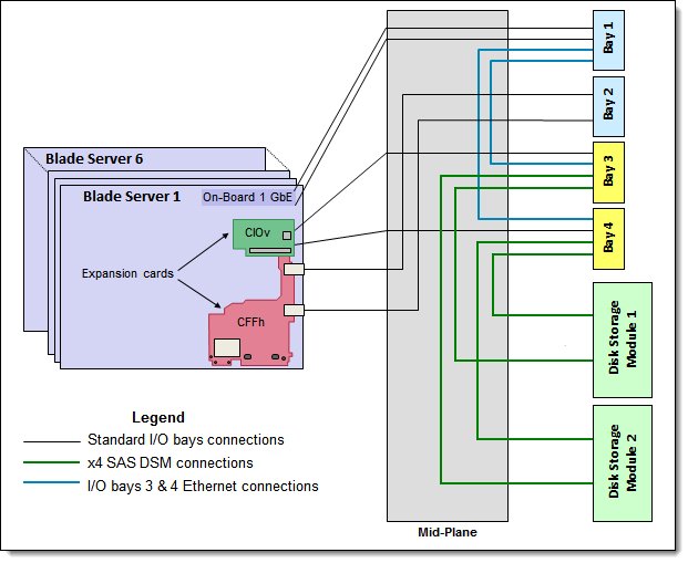
Figure 4. BladeCenter S I/O topology
Each of six blade bays has six dedicated I/O connections that are linked to four I/O bays, as shown in Figure 4:
- The two ports of the onboard Gigabit Ethernet controller in each blade server are both routed to I/O bay 1 in the chassis.
- Port 1 of the CIOv card in each blade server is routed to I/O bay 3.
- Port 2 of the CIOv card in each blade server is routed to I/O bay 4.
- Ports 1 and 2 of the CFFh card in each blade server are both routed to I/O bay 2.
In addition, I/O bays 3 and 4 have special wiring to enable the support of the disk drives that are installed in the integrated Disk Storage Modules (DSMs). This wiring consists of four x4 SAS links between these bays and DSMs (two links per I/O bay 3 or 4 connected to different DSMs). SAS links are only used when the DSMs are installed.
The following table shows the connections between adapter slots in the compute nodes to the switch bays in the chassis.
Table 5. Adapter to I/O bay correspondence
| I/O adapter in each server |
Port on the adapter | Corresponding I/O module bay in the chassis |
| Onboard 1 Gb Ethernet | Port 1 | I/O bay 1 |
| Port 2 | I/O bay 1 | |
| Onboard 10 Gb Ethernet (HS23)* | Port 1 | I/O bay 2 |
| Port 2 | I/O bay 2 | |
| CIOv adapter | Port 1 | I/O bay 3 |
| Port 2 | I/O bay 4 | |
| CFFh adapter** | Port 1 | I/O bay 2 |
| Port 2 | I/O bay 2 | |
| Port 3 | Not connected | |
| Port 4 | Not connected |
* Requires the 10Gb LOM Interposer Card be installed in HS23. Both 10 GbE ports are routed to the I/O bay 2 of the BladeCenter S chassis and operate at 1 Gbps speed.
** The only CFFh adapter that is supported in servers that are installed in the BladeCenter S is the 2/4 Port Ethernet Expansion Card (CFFh) for BladeCenter, 44W4479.
Disk Storage Module
The BladeCenter S chassis supports internal disk storage with the addition of one or two Disk Storage Modules (DSMs). Two DSMs are available as shown in the following table - a 6-drive DSM supporting 3.5-inch hot-swap disk drives and a 12-drive DSM supporting 2.5-inch hot-swap disk drives. Figure 2 shows the BladeCenter S with the 6-drive DSMs installed. The following figure shows the 12-drive DSM.
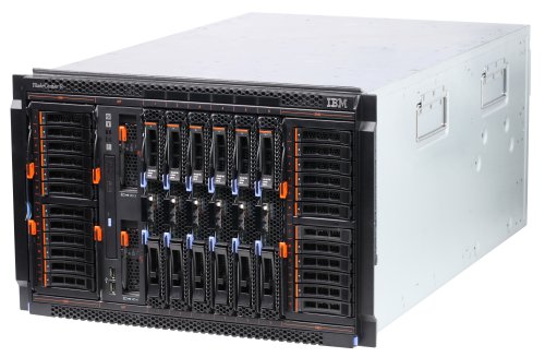
Figure 5. BladeCenter S with two BladeCenter S 12-Disk Storage Modules
The DSM is fundamentally a collection of disk drives that are made accessible to blade servers through a SAS switch module in the chassis and a SAS expansion card in each blade. You can install a maximum of two DSMs in the BladeCenter S chassis. The following table shows the ordering information. It is not supported to have one 12-drive DSM and one 6-drive DSM installed in the same chassis.
Table 6. Ordering part number and feature code
| Part number | Feature code |
Description | Maximum supported |
| 43W3581 | 1583 | BladeCenter S 6-Disk Storage Module | 2 |
| 49Y3234 | A3KS | BladeCenter S 12-Disk Storage Module | 2 |
Drives are assigned directly to blades by using built-in predefined configurations or through user-defined custom configurations. Both storage modules are accessible to all blades via a one or two SAS switch module. The SAS switch module is responsible for both the provisioning of physical disk drives through zoning and for failover redundancy when two SAS switch modules are present.
The use of the second SAS switch module provides higher levels of availability. When two SAS switch modules are installed, the modules provide redundant functionality because each module is able to access all hard disks in both storage modules. This enterprise-class redundant architecture allows the transparent data protection of all storage that is contained within the storage modules. With this enterprise-class redundant architecture, you can conduct the online replacement of either module.
The SAS Connectivity Card that is installed in each blade server connects the RAID controller in the blade server to the SAS switch in the chassis.
The following table lists the drives that are supported in the 6-drive and 12-drive DSMs. The table also lists which drives are supported in by the two SAS modules. The 12-drive DSM only supports the SAS RAID Controller Module so no 2.5-inch drives are supported with the SAS Connectivity Module.
Note: These supported 6 Gbps drives will operate at 3 Gbps when installed in the DSMs.
Table 7. Supported disk drives (Part 1 - 3.5" drives)
| Part number |
Feature code |
Description | Maximum supported |
Supported by SAS Connectivity Module |
Supported by SAS RAID Controller Module |
| 3.5-inch drives - supported in the BladeCenter S 6-Disk Storage Module only | |||||
| 42D0767 | 5417 | IBM 2 TB 7.2K 6 Gbps NL SAS 3.5" HS HDD |
6 per DSM (12 total) |
Yes | Yes |
| 42D0777 | 5418 | IBM 1 TB 7.2K 6 Gbps NL SAS 3.5" HS HDD |
6 per DSM (12 total) |
Yes | Yes |
| 43W7630 | 5561 | IBM 1 TB 7200 Dual Port SATA 3.5" HS HDD |
6 per DSM (12 total) |
Yes | No |
| 44W2234 | 5311 | IBM 300 GB 15K 6 Gbps SAS 3.5" Hot-Swap HDD |
6 per DSM (12 total) |
Yes | Yes |
| 44W2239 | 5312 | IBM 450 GB 15K 6 Gbps SAS 3.5" Hot-Swap HDD |
6 per DSM (12 total) |
Yes | Yes |
| 44W2244 | 5313 | IBM 600 GB 15K 6 Gbps SAS 3.5" Hot-Swap HDD |
6 per DSM (12 total) |
Yes | Yes |
Table 7. Supported disk drives (Part 2 - 2.5" drives)
| Part number |
Feature code |
Description | Maximum supported |
Supported by SAS Connectivity Module |
Supported by SAS RAID Controller Module |
| 2.5-inch drives - supported in the BladeCenter S 12-Disk Storage Module only | |||||
| 42D0637 | 5599 | IBM 300GB 2.5in SFF Slim-HS 10K 6Gbps SAS HDD |
12 per DSM (24 total) |
No | Yes |
| 90Y8877 | A2XC | IBM 300GB 2.5in SFF 10K 6Gbps HS SAS HDD |
12 per DSM (24 total) |
No | Yes |
| 90Y8872 | A2XD | IBM 600GB 2.5in SFF 10K 6Gbps HS SAS HDD |
12 per DSM (24 total) |
No | Yes |
| 81Y9650 | A282 | IBM 900GB 2.5in SFF HS 10K 6Gbps SAS HDD |
12 per DSM (24 total) |
No | Yes |
| 42D0677 | 5536 | IBM 146GB 2.5in SFF Slim-HS 15K 6Gbps SAS HDD |
12 per DSM (24 total) |
No | Yes |
| 81Y9670 | A283 | IBM 300GB 2.5in SFF HS 15K 6Gbps SAS HDD |
12 per DSM (24 total) |
No | Yes |
SAS RAID Controller Module
The SAS RAID Controller Module for BladeCenter S provides integrated RAID and SAS-based storage area networking capabilities for BladeCenter S-based solutions. Figure 5 shows the SAS RAID Controller Module.
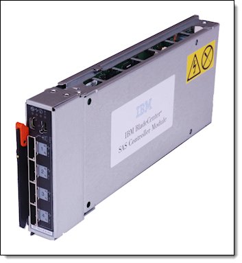
Figure 6. BladeCenter S SAS RAID Controller Module
The following table shows the ordering part numbers and feature codes.
Table 8. Ordering part numbers and feature codes
| Part number | Feature code |
Description | Maximum supported |
| 43W3584 | 5453 | BladeCenter S SAS RAID Controller Module. Includes one battery backup unit. |
2 |
| 00Y3447 | 7589 | BladeCenter RAID Battery Backup Module (replacement). | 2 |
Single controller configuration: Starting with SAS RAID Controller Firmware Version 1.2.2.007, a configuration that contains only one SAS RAID Controller Module is supported.
The SAS RAID Controller ships standard with a battery backup module as shown in Figure 6. The battery modules are installed in bays in the front of the chassis as shown in Figure 2.
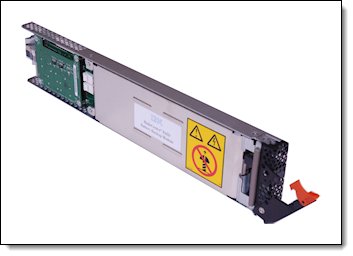
Figure 7. BladeCenter RAID Battery Backup Module
The SAS RAID Controller Module consists of two subsystems:
- RAID Controller to perform RAID management (working with storage pools, volumes, RAID levels, and host mappings)
- SAS Switch to provide SAS connectivity for blade servers and disks
The SAS RAID Controller Module has the following characteristics:
- Standard I/O module form factor
- Four external x4 3 Gb SAS links with a mini-SAS connector type (SFF-8088)
- Six internal x1 3 Gb SAS links to blade servers
- Two internal x4 3 Gb SAS links to the two Disk Storage Modules (DSMs)
- Internal Gb Ethernet interface for RAID management
- RAID levels that are supported: 0, 1, 5, and 10
- 512 MB of ECC battery-backed cache per controller
- A battery backup unit that provides up to 72 hours of data storage in cache in case of complete power failure
- 10/100 Mb Ethernet for I/O module management (monitoring status, updating firmware, configuring IP addresses, and so on)
- Serial SCSI Protocol (SSP)
- Serial Management Protocol (SMP) as defined in the SAS specification
- Link error detection
- Power-on diagnostics and status reporting
Ethernet switch required: A supported Ethernet switch must be installed in I/O bay 1. If the Intelligent Copper Pass-thru Module (44W4483) is used, ports 7 and 14 must be attached to each other by a standard Ethernet cable.
For information about supported external SAS devices, see Chapter 4 of the BladeCenter Interoperability Guide, which is available from http://lenovopress.com/bcig
SAS Connectivity Module
The SAS Connectivity Module is a SAS expander and provides the connectivity and access between the blades and the disks in the DSMs. It also provides four external SAS ports for further connectivity. The following data paths are controlled by predefined or user-defined zone configurations:
- Internal paths in the chassis from the blades to the disks
- Internal paths in the chassis from the blades to the external ports of the SAS Connectivity Module
Each blade must have the SAS Connectivity Card (or other supported SAS card) installed in the CIOv slot to allow it to connect to the storage by using the SAS Connectivity Module. The SAS Connectivity Module only provides the connectivity between the SAS devices that are installed in the BladeCenter S; the RAID controller on the blade server provides fault tolerance.
You can install up to two SAS Connectivity Modules in the BladeCenter S in I/O module bays 3 and 4. If you install only one SAS Connectivity Module, you must install it in I/O module bay 3. The following table shows the ordering part number and feature code.
Table 9. Ordering part number and feature code
| Part number | Feature code |
Description | Maximum supported |
| 39Y9195 | 2980 | BladeCenter SAS Connectivity Module | 2 |
Figure 7 shows the SAS Connectivity Module.
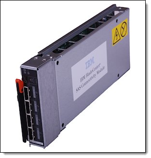
Figure 8. BladeCenter SAS Connectivity Module
The SAS Connectivity Module has the following characteristics:
- SAS expander
- Four external x4 links for storage servers with mini-SAS connector type (SFF-8088)
- 14 internal x1 links to blade servers
- Serial SCSI Protocol (SSP)
- Serial Management Protocol (SMP) as defined in the SAS specification
- Link error detection
- Power-on diagnostics and status reporting
For information about supported external SAS devices, see Chapter 4 of the BladeCenter Interoperability Guide, which is available from http://lenovopress.com/bcig
Media tray
The media tray for the BladeCenter S is a hot-swappable module that consists of the system LED panel, optical drive, two USB 2.0 ports, and two battery backup module bays. The system LED panel provides light path diagnostic LEDs, as well as power and location indicators. The media tray is accessible from the front of the chassis and is shown in Figure 2.
The optical drive and USB ports are available to any one blade server in the chassis. The drive and USB ports cannot be shared among multiple servers. The drive and USB ports can be used to install operating systems, to update drivers, or to copy data to recordable media.
For blade servers to access the drive and USB ports, they first must be assigned to a specific blade bay. This assignment is done either by physically pressing the media tray assignment button on the front of the blade server that you want or via the AMM web interface. After the drive and USB ports are assigned to a blade, they are not available to any other server in the chassis. If the devices are reassigned to another blade server, access is immediately dropped from the first server.
The following table lists the supported optical drives.
Table 10. Supported optical drives
| Part number | Feature code |
Description | Maximum supported |
| 46M0901 | 4161 | IBM UltraSlim Enhanced SATA DVD-ROM | 1 |
| 46M0902 | 4163 | IBM UltraSlim Enhanced SATA Multi-Burner | 1 |
IBM UltraSlim Enhanced SATA DVD-ROM (part number 46M0901) supports the following media and speeds for reading:
- CD-ROM 24X
- CD-DA (DAE) 20X
- CD-R 24X
- CD-RW 24X
- DVD-ROM (single layer) 8X
- DVD-ROM (dual layer) 8X
- DVD-R (4.7 GB) 6X
- DVD-R DL 4X
- DVD+R 6X
- DVD+R DL 4X
- DVD-RW (4.7 GB) 4X
- DVD+RW 4X
- DVD-RAM (4.7/9.4 GB) 4X
IBM UltraSlim Enhanced SATA Multi-Burner (part number 46M0902) supports the same media and speeds for reading as DVD-ROM (46M0901). In addition, this drive supports the following media and speeds for writing:
- CD-R 24X
- CD-RW 4X
- High Speed CD-RW 10X
- Ultra Speed CD-RW 16X
- Ultra Speed Plus CD-RW 16X
- DVD-R 8X
- DVD-R DL 6X
- DVD+R 8X
- DVD+R DL 6X
- DVD-RW 6X
- DVD+RW 8X
- DVD-RAM 5X
Serial Pass-thru Module
The Serial Pass-thru Module provides six serial port connectors that can be used to attach directly to each blade server in the BladeCenter S chassis via a four-wire serial RJ-45 connector. Port connector links bypass the AMM and provide a dedicated link directly to each blade. The Serial Pass-thru Module is installed in the dedicated bay at the rear of the chassis.
The following figure shows the Serial Pass-thru Module.

Figure 9. Serial Pass-thru Module
The following table lists the ordering information.
Table 11. Serial Pass-thru Module part number and feature code
| Part number | Feature code |
Description | Maximum supported |
| 43W3583 | 1584 | BladeCenter S Serial Pass-thru Module | 1 |
The port connections function at speeds of up to 19.2k baud and are intended for serial console access only. The port connectors are numbered from 1 to 6, from top to bottom, and correspond to blade servers in blade server bays 1 - 6.
Advanced Management Module
The Advanced Management Module (AMM) is a hot-swappable module that can be used to configure and manage any installed BladeCenter components. It provides system management functions and keyboard/video/mouse (KVM) multiplexing for all blade servers in the BladeCenter S unit that support KVM. The management module communicates with all components in the BladeCenter unit, detecting their presence or absence, reporting their status, and sending alerts for error conditions when required. The chassis supports one AMM.
The following figure shows the Advanced Management Module. See Figure 3 for the location of the AMM in the chassis.
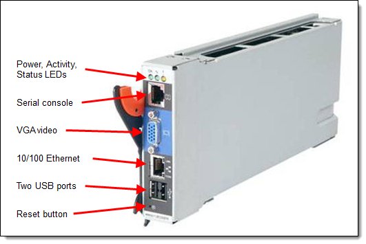
Figure 10. Advanced Management Module
BladeCenter components are configured by using the AMM web-based user interface. The web interface communicates with the management and configuration application, which is part of the upgradeable firmware that is installed in the management module.
You can use the AMM user interface to perform the following tasks:
- Defining the login IDs and passwords
- Configuring security settings, such as data encryption and user account security
- Selecting recipients for alert notification of specific events
- Monitoring the status of the BladeCenter chassis, blade servers, and other BladeCenter components
- Controlling the BladeCenter chassis, blade servers, and other BladeCenter components
- Accessing the I/O modules to configure them
- Changing the startup sequence in a blade server
- Setting the date and time
- Using a remote console for the blade servers
- Changing ownership of the keyboard, video, and mouse
- Changing ownership of the removable-media drives and USB ports
The AMM also incorporates a reset button that has two functions, depending on how long the button is pressed:
- Press and release the reset button to restart the management module.
- Press and hold the reset button for 8 seconds to restore the management module to the factory default settings.
When you press the reset button, the blowers operate at full speed while the management module is initializing.
The AMM has the following default static IPv4 address. By default, the AMM is configured to respond to Dynamic Host Configuration Protocol (DHCP) first before it uses its static IPv4 address:
- IP address: 192.168.70.125
- Subnet: 255.255.255.0
- User ID: USERID (all capital letters)
- Password: PASSW0RD (all capital letters, with a zero instead of the letter O)
Power supplies
The BladeCenter S supports up to four auto-sensing power modules, which can support either 110 V or 220 V ac power. Two power modules are standard, and a maximum of four power modules are supported.
The power modules are hot-swappable components and can be replaced easily during normal BladeCenter operation, assuming that a redundant power policy was selected in the AMM. If a power supply fails, the cooling fans inside the power supply continue to operate normally, because the power supply fans are powered from the “common” voltage from the midplane. This function is important, because the power supply fans cool the airflow to the storage modules. The following table shows the ordering information.
Table 12. Ordering part numbers and feature codes
| Part number | Feature code | Description |
| 43W3582 | 1992 | BladeCenter S 950 W/1450 W Auto-Sensing Power Supplies 3 & 4 IEC 320-C20 connector Includes power cords (2.5 m IEC 320 C19/C20, 16 A/125-250 V ac) |
| 46C7438 | 2102 | BladeCenter S C14 950 W/1450 W Auto-sensing Power Supplies 3 & 4 IEC 320-C14 connector Includes power cords (2.0 m IEC 320 C13/C14, 13 A/125 V-10A/250 V) |
Within the BladeCenter S chassis, all power supplies are combined into a single power domain that distributes power to each of the blade servers and modules through the system midplane.
The two standard power modules are installed in bay 1 and bay 2 of the chassis (the top and bottom module bays on the right side when you look from the back of the chassis, as shown in Figure 3). The second pair of power modules is required if any of these situations occur:
- The power requirements of the installed components (servers, I/O modules, disks, and so on) exceed the capacity of the standard two power modules.
- You install the second storage module because power modules 3 and 4 also provide the necessary fans to cool this second storage module.
Use the BladeCenter Power Configurator to confirm whether your configuration requires the second pair of power supplies: http://www.ibm.com/systems/bladecenter/powerconfig
Each power supply option includes two power cables, one for each power supply as listed in the previous table.
Physical specifications
Dimensions:
- Height: 306 mm (12 in)
- Width: 444 mm (17.5 in)
- Depth: 733 mm (28.9 in)
Weight:
- Minimum configuration: 40 kg (90 lb)
- Maximum configuration: 108 kg (240 lb)
Supported environment
The following environment is the supported operating environment.
Temperature and humidity:
- 10.0 - 35.0 ° C (50 - 95 ° F) at 0 - 914 m (0 - 3,000 ft)
- 10.0 - 32.0 °C (50 - 90 ° F) at 914 - 2,133 m (3,000 - 7,000 ft)
- Relative humidity: 8% - 80%
- Maximum altitude: 2,133 m (7,000 ft)
Supported electrical input:
- 200 - 240 V (nominal) ac; 50 Hz or 60 Hz
- 110 - 127 V (nominal) ac; 50 Hz or 60 Hz
Input kilovolt-amperes (kVA) (approximately):
- Minimum configuration: 0.40 kVA (two power supplies)
- Maximum configuration: 3.50 kVA (four power supplies)
Thermal output:
- Ship configuration — 1365 Btu/hr (400 watts)
- Full configuration — 11942 Btu/hr (3500 watts)
Acoustical noise emissions for BladeCenter with six blade servers:
- 6.3 through 6.9 bels blade-dependent (operating)
- 6.3 through 6.9 bels blade-dependent (idling)
The noise emission level stated is the declared (upper limit) sound power level, in bels, for a random sample of machines. All measurements are made in accordance with ISO 7779 and reported in conformance with ISO 9296.
Warranty options
The BladeCenter S has a three-year on-site warranty with 9x5 next-business-day terms. IBM offers the warranty service upgrades through IBM ServicePac®. The IBM ServicePac is a series of prepackaged warranty maintenance upgrades and post-warranty maintenance agreements with a well-defined scope of services, including service hours, response time, term of service, and service agreement terms and conditions.
IBM ServicePac offerings are country-specific. That is, each country might have its own service types, service levels, response times, and terms and conditions. Not all covered types of ServicePac might be available in a particular country. For more information about the IBM ServicePac offerings that are available in your country, see the IBM ServicePac Product Selector at https://www-304.ibm.com/sales/gss/download/spst/servicepac.
The following table explains warranty service definitions in more detail.
Table 13. Warranty service definitions
| Term | Description |
| IBM on-site repair (IOR) | A service technician comes to the server's location for equipment repair. |
| 24x7x2 hour | A service technician is scheduled to arrive at your client’s location within two hours after remote problem determination is completed. We provide 24-hour service, every day, including IBM holidays. |
| 24x7x4 hour | A service technician is scheduled to arrive at your client’s location within four hours after remote problem determination is completed. We provide 24-hour service, every day, including IBM holidays. |
| 9x5x4 hour | A service technician is scheduled to arrive at your client’s location within four business hours after remote problem determination is completed. We provide service from 8:00 a.m. to 5:00 p.m. in the client's local time zone, Monday through Friday, excluding IBM holidays. If, after 1:00 p.m., it is determined that on-site service is required, the client can expect the service technician to arrive the morning of the following business day. For noncritical service requests, a service technician arrives by the end of the following business day. |
| 9x5 next business day | A service technician is scheduled to arrive at your client’s location on the business day after we receive your call, following remote problem determination. We provide service from 8:00 a.m. to 5:00 p.m. in the client's local time zone, Monday through Friday, excluding IBM holidays. |
In general, the following types of IBM ServicePacs exist:
- Warranty and maintenance service upgrades:
- One, two, three, four, or five years of 9x5 or 24x7 service coverage
- On-site repair from the next business day to four or two hours
- One or two years of warranty extension
- Remote technical support services:
- One or three years with 24x7 coverage (severity 1) or 9 - 5 next business day for all severities
- Installation and start-up support for System x servers
- Remote technical support for System x servers
- Software support - Support Line:
- Microsoft or Linux software
- VMware
- IBM Systems Director
Regulatory compliance
The server conforms to the following standards:
- FCC - Verified to comply with Part 15 of the FCC Rules, Class A
- Canada ICES-003, issue 4, Class A
- UL/IEC 60950-1
- CAN C22.2 No. 60950-1-03
- NOM-019
External disk storage systems
Lenovo offers the ThinkSystem DE Series and ThinkSystem DM Series external storage systems for high-performance storage. See the DE Series and DM Series product guides for specific controller models, expansion enclosures and configuration options:
- ThinkSystem DE Series Storage
https://lenovopress.com/storage/thinksystem/de-series#rt=product-guide - ThinkSystem DM Series Storage
https://lenovopress.com/storage/thinksystem/dm-series#rt=product-guide - ThinkSystem DG Series Storage
https://lenovopress.com/storage/thinksystem/dg-series#rt=product-guide
External backup units
The following table lists the external backup options that are offered by Lenovo.
| Part number | Description |
|---|---|
| External RDX USB drives | |
| 4T27A10725 | ThinkSystem RDX External USB 3.0 Dock |
| External SAS tape backup drives | |
| 6160S7E | IBM TS2270 Tape Drive Model H7S |
| 6160S8E | IBM TS2280 Tape Drive Model H8S |
| 6160S9E | IBM TS2290 Tape Drive Model H9S |
| External SAS tape backup autoloaders | |
| 6171S7R | IBM TS2900 Tape Autoloader w/LTO7 HH SAS |
| 6171S8R | IBM TS2900 Tape Autoloader w/LTO8 HH SAS |
| 6171S9R | IBM TS2900 Tape Autoloader w/LTO9 HH SAS |
| External tape backup libraries | |
| 6741A1F | IBM TS4300 3U Tape Library-Base Unit |
| 6741A3F | IBM TS4300 3U Tape Library-Expansion Unit |
| Full High 8 Gb Fibre Channel for TS4300 | |
| 01KP938 | LTO 7 FH Fibre Channel Drive |
| 01KP954 | LTO 8 FH Fibre Channel Drive |
| 02JH837 | LTO 9 FH Fibre Channel Drive |
| Half High 8 Gb Fibre Channel for TS4300 | |
| 01KP936 | LTO 7 HH Fibre Channel Drive |
| 01KP952 | LTO 8 HH Fibre Channel Drive |
| 02JH835 | LTO 9 HH Fibre Channel Drive |
| Half High 6 Gb SAS for TS4300 | |
| 01KP937 | LTO 7 HH SAS Drive |
| 01KP953 | LTO 8 HH SAS Drive |
| 02JH836 | LTO 9 HH SAS Drive |
For more information, see the list of Product Guides in the Backup units category:
https://lenovopress.com/servers/options/backup
Top-of-rack Ethernet switches
The following table lists the Ethernet LAN switches that are offered by Lenovo.
| Part number | Description |
|---|---|
| 1 Gb Ethernet Rack switches | |
| 7Y810011WW | Lenovo ThinkSystem NE0152T RackSwitch (Rear to Front) |
| 7Z320O11WW | Lenovo ThinkSystem NE0152TO RackSwitch (Rear to Front, ONIE) |
| 7159BAX | Lenovo RackSwitch G7028 (Rear to Front) |
| 7159CAX | Lenovo RackSwitch G7052 (Rear to Front) |
| 7159G52 | Lenovo RackSwitch G8052 (Rear to Front) |
| 7165H1X | Juniper EX2300-C PoE Switch |
| 7165H2X | Juniper EX2300-24p PoE Switch |
| 1 Gb Ethernet Campus switches | |
| 7Z340011WW | Lenovo CE0128TB Switch (3-Year Warranty) |
| 7Z360011WW | Lenovo CE0128TB Switch (Limited Lifetime Warranty) |
| 7Z340012WW | Lenovo CE0128PB Switch (3-Year Warranty) |
| 7Z360012WW | Lenovo CE0128PB Switch (Limited Lifetime Warranty) |
| 7Z350021WW | Lenovo CE0152TB Switch (3-Year Warranty) |
| 7Z370021WW | Lenovo CE0152TB Switch (Limited Lifetime Warranty) |
| 7Z350022WW | Lenovo CE0152PB Switch (3-Year Warranty) |
| 7Z370022WW | Lenovo CE0152PB Switch (Limited Lifetime Warranty) |
| 10 Gb Ethernet switches | |
| 7159A1X | Lenovo ThinkSystem NE1032 RackSwitch (Rear to Front) |
| 7159B1X | Lenovo ThinkSystem NE1032T RackSwitch (Rear to Front) |
| 7Z330O11WW | Lenovo ThinkSystem NE1064TO RackSwitch (Rear to Front, ONIE) |
| 7159C1X | Lenovo ThinkSystem NE1072T RackSwitch (Rear to Front) |
| 7159CRW | Lenovo RackSwitch G8272 (Rear to Front) |
| 7159GR6 | Lenovo RackSwitch G8296 (Rear to Front) |
| 7159BR6 | Lenovo RackSwitch G8124E (Rear to Front) |
| 25 Gb Ethernet switches | |
| 7159E1X | Lenovo ThinkSystem NE2572 RackSwitch (Rear to Front) |
| 7Z210O21WW | Lenovo ThinkSystem NE2572O RackSwitch (Rear to Front, ONIE) |
| 7Z330O21WW | Lenovo ThinkSystem NE2580O RackSwitch (Rear to Front, ONIE) |
| 100 Gb Ethernet switches | |
| 7159D1X | Lenovo ThinkSystem NE10032 RackSwitch (Rear to Front) |
| 7Z210O11WW | Lenovo ThinkSystem NE10032O RackSwitch (Rear to Front, ONIE) |
For more information, see the list of Product Guides in the following switch categories:
- 1 Gb Ethernet switches: http://lenovopress.com/networking/tor/1gb?rt=product-guide
- 10 Gb Ethernet switches: http://lenovopress.com/networking/tor/10gb?rt=product-guide
- 25 Gb Ethernet switches: http://lenovopress.com/networking/tor/25gb?rt=product-guide
- 40 Gb Ethernet switches: http://lenovopress.com/networking/tor/40gb?rt=product-guide
- 100 Gb Ethernet switches: https://lenovopress.com/networking/tor/100Gb?rt=product-guide
Power distribution units
The following table lists the power distribution units (PDUs) that are offered by Lenovo.
| Part number |
Feature code |
Description |
ANZ
|
ASEAN
|
Brazil
|
EET
|
MEA
|
RUCIS
|
WE
|
HTK
|
INDIA
|
JAPAN
|
LA
|
NA
|
PRC
|
|---|---|---|---|---|---|---|---|---|---|---|---|---|---|---|---|
| 0U Basic PDUs | |||||||||||||||
| 00YJ776 | ATZY | 0U 36 C13/6 C19 24A 1 Phase PDU | N | Y | Y | N | N | N | N | N | N | Y | Y | Y | N |
| 00YJ779 | ATZX | 0U 21 C13/12 C19 48A 3 Phase PDU | N | N | Y | N | N | N | Y | N | N | Y | Y | Y | N |
| 00YJ777 | ATZZ | 0U 36 C13/6 C19 32A 1 Phase PDU | Y | Y | N | Y | Y | Y | Y | Y | Y | N | N | Y | Y |
| 00YJ778 | AU00 | 0U 21 C13/12 C19 32A 3 Phase PDU | Y | Y | N | Y | Y | Y | Y | Y | Y | N | N | Y | Y |
| 0U Switched and Monitored PDUs | |||||||||||||||
| 00YJ783 | AU04 | 0U 12 C13/12 C19 Switched and Monitored 48A 3 Phase PDU | N | N | Y | N | N | N | Y | N | N | Y | Y | Y | N |
| 00YJ781 | AU03 | 0U 20 C13/4 C19 Switched and Monitored 24A 1 Phase PDU | N | N | Y | N | Y | N | Y | N | N | Y | Y | Y | N |
| 00YJ782 | AU02 | 0U 18 C13/6 C19 Switched and Monitored 32A 3 Phase PDU | Y | Y | Y | Y | Y | Y | Y | Y | Y | N | Y | N | Y |
| 00YJ780 | AU01 | 0U 20 C13/4 C19 Switched and Monitored 32A 1 Phase PDU | Y | Y | Y | Y | Y | Y | Y | Y | Y | N | Y | N | Y |
| 1U Switched and Monitored PDUs | |||||||||||||||
| 4PU7A81117 | BNDV | 1U 18 C19/C13 switched and monitored 48A 3P WYE PDU - ETL | N | N | N | N | N | N | N | N | N | N | N | Y | N |
| 4PU7A77467 | BLC4 | 1U 18 C19/C13 Switched and Monitored 80A 3P Delta PDU | N | N | N | N | N | N | N | N | N | Y | N | Y | N |
| 4PU7A77469 | BLC6 | 1U 12 C19/C13 switched and monitored 60A 3P Delta PDU | N | N | N | N | N | N | N | N | N | N | N | Y | N |
| 4PU7A77468 | BLC5 | 1U 12 C19/C13 switched and monitored 32A 3P WYE PDU | Y | Y | Y | Y | Y | Y | Y | Y | Y | N | Y | Y | Y |
| 4PU7A81118 | BNDW | 1U 18 C19/C13 switched and monitored 48A 3P WYE PDU - CE | Y | Y | Y | Y | Y | Y | Y | Y | Y | N | Y | N | Y |
| 46M4002 | 5896 | 1U 9 C19/3 C13 Switched and Monitored DPI PDU | Y | Y | Y | Y | Y | Y | Y | Y | Y | Y | Y | Y | Y |
| 46M4004 | 5894 | 1U 12 C13 Switched and Monitored DPI PDU | Y | Y | Y | Y | Y | Y | Y | Y | Y | Y | Y | Y | Y |
| 46M4003 | 5897 | 1U 9 C19/3 C13 Switched and Monitored 60A 3 Phase PDU | Y | Y | Y | Y | Y | Y | Y | Y | Y | Y | Y | Y | Y |
| 46M4005 | 5895 | 1U 12 C13 Switched and Monitored 60A 3 Phase PDU | Y | Y | Y | Y | Y | Y | Y | Y | Y | Y | Y | Y | Y |
| 1U Ultra Density Enterprise PDUs (9x IEC 320 C13 + 3x IEC 320 C19 outlets) | |||||||||||||||
| 71763NU | 6051 | Ultra Density Enterprise C19/C13 PDU 60A/208V/3PH | N | N | Y | N | N | N | N | N | N | Y | Y | Y | N |
| 71762NX | 6091 | Ultra Density Enterprise C19/C13 PDU Module | Y | Y | Y | Y | Y | Y | Y | Y | Y | Y | Y | Y | Y |
| 1U C13 Enterprise PDUs (12x IEC 320 C13 outlets) | |||||||||||||||
| 39M2816 | 6030 | DPI C13 Enterprise PDU Plus Module (WW) | Y | Y | Y | Y | Y | Y | Y | Y | Y | Y | Y | Y | Y |
| 39Y8941 | 6010 | DPI C13 Enterprise PDU Module (WW) | Y | Y | Y | Y | Y | Y | Y | Y | Y | Y | Y | Y | Y |
| 1U C19 Enterprise PDUs (6x IEC 320 C19 outlets) | |||||||||||||||
| 39Y8948 | 6060 | DPI C19 Enterprise PDU Module (WW) | Y | Y | Y | Y | Y | Y | Y | Y | Y | Y | Y | Y | Y |
| 39Y8923 | 6061 | DPI Three-phase 60A/208V C19 Enterprise PDU (US) | N | N | Y | N | N | N | Y | N | N | N | Y | Y | N |
| 1U Front-end PDUs (3x IEC 320 C19 outlets) | |||||||||||||||
| 39Y8938 | 6002 | DPI Single-phase 30A/120V Front-end PDU (US) | Y | Y | Y | Y | Y | Y | Y | Y | Y | Y | Y | Y | Y |
| 39Y8939 | 6003 | DPI Single-phase 30A/208V Front-end PDU (US) | Y | Y | Y | Y | Y | Y | Y | Y | Y | Y | Y | Y | Y |
| 39Y8934 | 6005 | DPI Single-phase 32A/230V Front-end PDU (International) | Y | Y | Y | Y | Y | Y | Y | Y | Y | Y | Y | Y | Y |
| 39Y8940 | 6004 | DPI Single-phase 60A/208V Front-end PDU (US) | Y | N | Y | Y | Y | Y | Y | N | N | Y | Y | Y | N |
| 39Y8935 | 6006 | DPI Single-phase 63A/230V Front-end PDU (International) | Y | Y | Y | Y | Y | Y | Y | Y | Y | Y | Y | Y | Y |
| 1U NEMA PDUs (6x NEMA 5-15R outlets) | |||||||||||||||
| 39Y8905 | 5900 | DPI 100-127V NEMA PDU | Y | Y | Y | Y | Y | Y | Y | Y | Y | Y | Y | Y | Y |
| Line cords for 1U PDUs that ship without a line cord | |||||||||||||||
| 40K9611 | 6504 | 4.3m, 32A/380-415V, EPDU/IEC 309 3P+N+G 3ph wye (non-US) Line Cord | Y | Y | Y | Y | Y | Y | Y | Y | Y | Y | Y | Y | Y |
| 40K9612 | 6502 | 4.3m, 32A/230V, EPDU to IEC 309 P+N+G (non-US) Line Cord | Y | Y | Y | Y | Y | Y | Y | Y | Y | Y | Y | Y | Y |
| 40K9613 | 6503 | 4.3m, 63A/230V, EPDU to IEC 309 P+N+G (non-US) Line Cord | Y | Y | Y | Y | Y | Y | Y | Y | Y | Y | Y | Y | Y |
| 40K9614 | 6500 | 4.3m, 30A/208V, EPDU to NEMA L6-30P (US) Line Cord | Y | Y | Y | Y | Y | Y | Y | Y | Y | Y | Y | Y | Y |
| 40K9615 | 6501 | 4.3m, 60A/208V, EPDU to IEC 309 2P+G (US) Line Cord | N | N | Y | N | N | N | Y | N | N | Y | Y | Y | N |
| 40K9617 | 6505 | 4.3m, 32A/230V, Souriau UTG Female to AS/NZ 3112 (Aus/NZ) Line Cord | Y | Y | Y | Y | Y | Y | Y | Y | Y | Y | Y | Y | Y |
| 40K9618 | 6506 | 4.3m, 32A/250V, Souriau UTG Female to KSC 8305 (S. Korea) Line Cord | Y | Y | Y | Y | Y | Y | Y | Y | Y | Y | Y | Y | Y |
For more information, see the Lenovo Press documents in the PDU category:
https://lenovopress.com/servers/options/pdu
Uninterruptible power supply units
The following table lists the uninterruptible power supply (UPS) units that are offered by Lenovo.
| Part number | Description |
|---|---|
| 55941AX | RT1.5kVA 2U Rack or Tower UPS (100-125VAC) |
| 55941KX | RT1.5kVA 2U Rack or Tower UPS (200-240VAC) |
| 55942AX | RT2.2kVA 2U Rack or Tower UPS (100-125VAC) |
| 55942KX | RT2.2kVA 2U Rack or Tower UPS (200-240VAC) |
| 55943AX | RT3kVA 2U Rack or Tower UPS (100-125VAC) |
| 55943KX | RT3kVA 2U Rack or Tower UPS (200-240VAC) |
| 55945KX | RT5kVA 3U Rack or Tower UPS (200-240VAC) |
| 55946KX | RT6kVA 3U Rack or Tower UPS (200-240VAC) |
| 55948KX | RT8kVA 6U Rack or Tower UPS (200-240VAC) |
| 55949KX | RT11kVA 6U Rack or Tower UPS (200-240VAC) |
| 55948PX | RT8kVA 6U 3:1 Phase Rack or Tower UPS (380-415VAC) |
| 55949PX | RT11kVA 6U 3:1 Phase Rack or Tower UPS (380-415VAC) |
| 55943KT† | ThinkSystem RT3kVA 2U Standard UPS (200-230VAC) (2x C13 10A, 2x GB 10A, 1x C19 16A outlets) |
| 55943LT† | ThinkSystem RT3kVA 2U Long Backup UPS (200-230VAC) (2x C13 10A, 2x GB 10A, 1x C19 16A outlets) |
| 55946KT† | ThinkSystem RT6kVA 5U UPS (200-230VAC) (2x C13 10A outlets, 1x Terminal Block output) |
| 5594XKT† | ThinkSystem RT10kVA 5U UPS (200-230VAC) (2x C13 10A outlets, 1x Terminal Block output) |
† Only available in China and the Asia Pacific market.
For more information, see the list of Product Guides in the UPS category:
https://lenovopress.com/servers/options/ups
Rack cabinets
The BladeCenter S chassis is supported in the rack cabinets that are listed in the following table. In an office environment, the suggested rack is the BladeCenter S Office Enablement Kit.
Table 18. Rack cabinets
| Part number | Description |
| 201886X | BladeCenter S Office Enablement Kit |
| 93072PX | IBM 25U Static S2 Standard Rack |
| 93072RX | IBM 25U Standard Rack |
| 93074RX | IBM 42U Standard Rack |
| 93074XX | IBM 42U Standard Rack Extension |
| 93084EX | IBM 42U Enterprise Expansion Rack |
| 93084PX | IBM 42U Enterprise Rack |
| 93604EX | IBM 42U 1200mm Deep Dynamic Expansion Rack |
| 93604PX | IBM 42U 1200mm Deep Dynamic Rack |
| 93614EX | IBM 42U 1200mm Deep Static Expansion Rack |
| 93614PX | IBM 42U 1200mm Deep Static Rack |
| 93624EX | IBM 47U 1200mm Deep Static Expansion Rack |
| 93624PX | IBM 47U 1200mm Deep Static Rack |
| 93634CX | IBM PureFlex™ System 42U Rack |
| 93634DX | IBM PureFlex System 42U Expansion Rack |
| 93634EX | IBM 42U 1100mm Dynamic Expansion Rack |
| 93634PX | IBM 42U 1100mm Dynamic Rack |
| 99564RX | IBM S2 42U Dynamic Standard Rack |
| 99564XX | IBM S2 42U Dynamic Standard Expansion Rack |
For more information, see the list of Lenovo Press Product Guides in the Rack cabinets category:
https://lenovopress.com/servers/options/racks
The BladeCenter S Office Enablement Kit, part number 201886X, is an enclosure that is designed for the BladeCenter S chassis for use in offices without a dedicated server room, or where the dust level is high. The enclosure with the BladeCenter S chassis and Flat Panel Monitor kit installed is shown in the following figure.
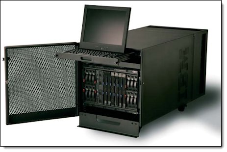
Figure 11. BladeCenter S Office Enablement Kit
Based on the NetBAY11, the Office Enablement Kit is an 11U enclosure with security doors, special acoustics, and air filtration to suit office environments. With the BladeCenter S chassis installed, an extra 4U of space is left to hold other rack devices.
The Office Enablement Kit offers the following benefits:
- Acoustical module: The Office Enablement Kit comes with an acoustical module that helps make BladeCenter S quiet for the office environment while providing easy access to the BladeCenter S components.
- Locking door: Security is an important consideration in any office environment. The Office Enablement Kit comes with a front locking door that helps ensure that your data remains safe and secure in any environment.
- 4U of extra space for other devices: Different businesses use different tools to enable their office IT. The Office Enablement Kit includes 4U of extra space for other types of IT that an office might need. This space can take any IT that fits into a 4U or smaller standard rack space.
- Easily mobile: The Office Enablement Kit comes with lockable wheels to make your BladeCenter S easily transportable.
The Office Enablement Kit also supports an optional air contaminant filter for BladeCenter S chassis that are deployed in dusty environments. Ordering information is listed in the following table.
Table 19. Air contaminant filter ordering information
| Part number | Feature code | Description |
| 43X0340 | 4024 | BladeCenter Airborne Contaminant Filter |
| 43X0437 | 4025 | BladeCenter Airborne Contaminant Replacement Filters (4-Pack) |
The Office Enablement Kit has the following approximate dimensions and weight:
- Height: 611 mm (24.1 in)
- Width: 518 mm (20.4 in)
- Depth: 1,155.7 mm (45.5 in)
- Empty weight: 41 kg (91 lb)
- Total rack weight: 224 kg (493 lb)
Rack options
The BladeCenter S chassis supports the rack console switches and monitor kits that are listed in the following table.
Table 20. Rack options
| Part number | Description |
| Monitor kits and keyboard trays | |
| 172317X | 1U 17 in Flat Panel Console Kit |
| 172319X | 1U 19 in Flat Panel Console Kit |
| Console switches | |
| 1754D2X | IBM Global 4x2x32 Console Manager (GCM32) |
| 1754D1X | IBM Global 2x2x16 Console Manager (GCM16) |
| 1754A2X | IBM Local 2x16 Console Manager (LCM16) |
| 1754A1X | IBM Local 1x8 Console Manager (LCM8) |
| Rack conversion options | |
| 46M5382 | IBM Serial Conversion Option (SCO) |
| 46M5383 | IBM Virtual Media Conversion Option Gen2 (VCO2) |
| 39M2895 | IBM USB Conversion Option (UCO) |
For more information, see the list of Lenovo Press Product Guides in the KVM Switches & Consoles category:
https://lenovopress.com/servers/options/kvm
Lenovo Financial Services
Lenovo Financial Services reinforces Lenovo’s commitment to deliver pioneering products and services that are recognized for their quality, excellence, and trustworthiness. Lenovo Financial Services offers financing solutions and services that complement your technology solution anywhere in the world.
We are dedicated to delivering a positive finance experience for customers like you who want to maximize your purchase power by obtaining the technology you need today, protect against technology obsolescence, and preserve your capital for other uses.
We work with businesses, non-profit organizations, governments and educational institutions to finance their entire technology solution. We focus on making it easy to do business with us. Our highly experienced team of finance professionals operates in a work culture that emphasizes the importance of providing outstanding customer service. Our systems, processes and flexible policies support our goal of providing customers with a positive experience.
We finance your entire solution. Unlike others, we allow you to bundle everything you need from hardware and software to service contracts, installation costs, training fees, and sales tax. If you decide weeks or months later to add to your solution, we can consolidate everything into a single invoice.
Our Premier Client services provide large accounts with special handling services to ensure these complex transactions are serviced properly. As a premier client, you have a dedicated finance specialist who manages your account through its life, from first invoice through asset return or purchase. This specialist develops an in-depth understanding of your invoice and payment requirements. For you, this dedication provides a high-quality, easy, and positive financing experience.
For your region-specific offers, please ask your Lenovo sales representative or your technology provider about the use of Lenovo Financial Services. For more information, see the following Lenovo website:
https://www.lenovo.com/us/en/landingpage/lenovo-financial-services/
Trademarks
Lenovo and the Lenovo logo are trademarks or registered trademarks of Lenovo in the United States, other countries, or both. A current list of Lenovo trademarks is available on the Web at https://www.lenovo.com/us/en/legal/copytrade/.
The following terms are trademarks of Lenovo in the United States, other countries, or both:
Lenovo®
BladeCenter Interoperability Guide
BladeCenter®
MAX5
RackSwitch
ServerProven®
System x®
ThinkSystem®
The following terms are trademarks of other companies:
Intel® and Xeon® are trademarks of Intel Corporation or its subsidiaries.
Linux® is the trademark of Linus Torvalds in the U.S. and other countries.
Microsoft® and Windows® are trademarks of Microsoft Corporation in the United States, other countries, or both.
Other company, product, or service names may be trademarks or service marks of others.


