

Top
Abstract
The Flex System IB6131 InfiniBand Switch is designed to offer the performance you need to support clustered databases, parallel processing, transactional services, and high-performance embedded I/O applications, helping to reduce task completion time and lower the cost per operation. The switch supports 40 Gbps QDR InfiniBand and can be upgraded to 56 Gbps FDR InfiniBand.
Introduction
The Flex System IB6131 InfiniBand Switch is designed to offer the performance you need to support clustered databases, parallel processing, transactional services, and high-performance embedded I/O applications, helping to reduce task completion time and lower the cost per operation. The switch supports 40 Gbps QDR InfiniBand and can be upgraded to 56 Gbps FDR InfiniBand.
The Flex System IB6131 InfiniBand Switch can be installed in the Flex System chassis, which provides a high bandwidth, low latency fabric for Enterprise Data Centers (EDC), high-performance computing (HPC), and embedded environments. When used in conjunction with IB6132 InfiniBand QDR and FDR dual-port mezzanine I/O cards, these switches will achieve significant performance improvements resulting in reduced completion time and lower cost per operation.
Figure 1 shows the switch module.
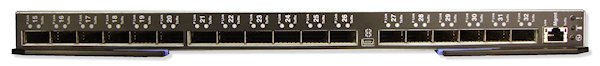
Figure 1. Flex System IB6131 InfiniBand Switch
Did you know?
This switch is designed for low latency, high bandwidth, and computing efficiency for performance-driven server and storage clustering applications. The switch supports full bisectional bandwidth, and, when combined with the InfiniBand 56 Gbps FDR adapter, your organization can achieve efficient high-performance computing by providing maximum bandwidth and off-loading from the CPU protocol processing and data movement overhead, such as Remote Direct Memory Access (RDMA) and Send/Receive semantics, allowing more processor power for the application.
Flex System, a new category of computing and the next generation of Smarter Computing, offers intelligent workload deployment and management for maximum business agility. This chassis delivers high-speed performance complete with integrated servers, storage, and networking for multiple chassis management in data center compute environments. Furthermore, its flexible design can meet the needs of varying workloads with independently scalable IT resource pools for higher utilization and lower cost per workload. While increased security and resiliency protect vital information and promote maximum uptime, the integrated, easy-to-use management system reduces setup time and complexity, providing a quicker path to a return on investment (ROI).
Part number information
The Flex System IB6131 InfiniBand Switch base enables 14 internal Quad Data Rate (QDR) links to each compute node and 18 Quad Small Form-factor Pluggable (QSFP) uplink ports for inter-switch links or to connect to external servers. Clients can upgrade to FDR speed (56 Gb) via the Feature On Demand (FOD) process. The following table shows the part numbers for ordering the switch and upgrade.
| Description | Part number | Feature codes* |
| Flex System IB6131 InfiniBand Switch | 90Y3450 | A1EK / 3699 |
| Flex System IB6131 InfiniBand Switch (FDR Upgrade) | 90Y3462 | A1QX / None |
* The first feature code listed is for configurations ordered through the System x® sales channel. The second feature code is for configurations ordered through the IBM Power Systems™ sales channel.
The part number for the switch, 90Y3450, includes the following items:
- One Flex System IB6131 InfiniBand Switch
- Documentation package
Note: IB6131 supports QDR and FDR copper QSFP cables to connect to other devices or servers. No cables are included with the switch.
The part number for the upgrade, 90Y3462, includes the following items:
- Feature on Demand Activation Flyer
- Upgrade activation key
The base switch and upgrades are as follows:
- 90Y3450 is the part number for the physical device and comes with 14 internal QDR ports enabled, one to each compute node, and 18 external QDR ports enabled to connect to a server or other InfiniBand devices. All external ports are QSFP-based connections.
- 90Y3462 can be applied on the base switch (one upgrade per switch) to enable FDR on all ports (both internal and external).
Supported cables
The following table lists the supported cables.
| Part number | Feature code* | Description |
| Serial cables | ||
| 90Y9338 | A2RR / None | Flex System Management Serial Access Cable Kit |
| InfiniBand QSFP cables | ||
| 90Y3470 | A227 / None | 3m FDR InfiniBand Cable |
| None | None / 3249 | QDR InfiniBand 3M QSFP Cable |
* The first feature code listed is for configurations made through x-config (HVEC). The second feature code is for configurations ordered through e-config (AAS).
Benefits
- Ultra high performance with full bisectional bandwidth at both Fourteen Data Rate (FDR) and Quad Data Rate (QDR) speeds
- Capability of up to 18 uplink ports for 14 servers allowing high-speed throughput with zero oversubscription
- Suited for clients running InfiniBand infrastructure in High Performance Computing and Financial Services
- When operating at FDR speed, less than 170 nanoseconds measured latency node to node — nearly half of the typical QDR InfiniBand latency
- Forward Error Correction–resilient
- Low power consumption
- Capability to scale to larger node counts to create a low latency clustered solution and reduce packet hops
Features and specifications
The Flex System IB6131 InfiniBand Switch has the following features and specifications:
- Internal ports:
- Fourteen internal ports that can operate at 40 Gbps QDR or 56 Gbps FDR. An optional Feature-on-Demand (FoD) upgrade is required to enable ports to operate at 56 Gbps. FDR requires IB6131 FDR InfiniBand Adapter (90Y3454).
- One 1 GbE port is connected to the chassis management module.
- External ports:
- Eighteen QSFP ports auto-sensing 10 Gbps, 20 Gbps, or 40 Gbps QDR (or 56 Gbps FDR with optional upgrade) supporting QSFP copper direct-attach cables (DAC). DAC cables are not included and must be purchased separately.
- One RS-232 serial port (mini-USB connector) that provides an additional means to configure the switch module.
- One external Ethernet port with RJ-45 connector for switch configuration and management.
- The InfiniBand QDR and FDR switches based on Mellanox technology are unmanaged switches. No embedded subnet manager. Switch requires subnet management from an external source.
- InfiniBand Trade Association (IBTA) 1.3 and 1.21 compliant.
- PowerPC® based MLNX-OS management.
- InfiniBand: Auto-negotiation of 10 Gbps, 20 Gbps, 40 Gbps, or 56 Gbps.
- Mellanox quality of service (QoS): Nine InfiniBand virtual lanes for all ports, eight data transport lanes, and one management lane.
- Management: Baseboard, performance, and device management agents for full InfiniBand in-band management.
- Switching performance: Simultaneous wire-speed any port to any port.
- Addressing: 48,000 unicast addresses maximum per subnet, 16,000 multicast addresses per subnet.
- Switching capacity: 2 Tbps for FDR and 1.44 Tbps for QDR
Standards supported
The module supports the following standard:
- IBTA (InfiniBand Trade Association) 1.3 compliant
Supported chassis and adapter cards
The switches are installed in switch bays in the rear of the Flex System Enterprise Chassis, as shown in Figure 2.
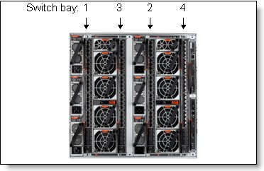
Figure 2. Location of the switch bays in the Flex System Enterprise Chassis
The connections between the adapters installed in the compute nodes to the switch bays in the chassis are shown diagrammatically in Figure 3. Figure 3 shows both half-wide servers, such as the x240 with two adapters, and full-wide servers, such as the x440 with four adapters.
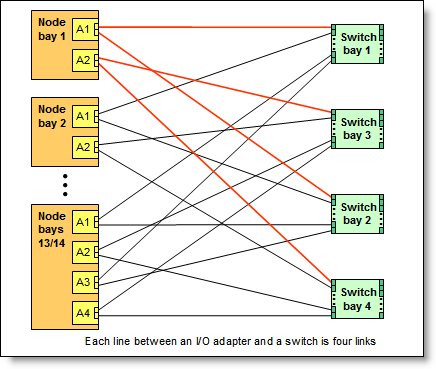
Figure 3. Logical layout of the interconnects between I/O adapters and I/O modules
The Flex System IB6131 InfiniBand Switch can be installed in bays 1, 2, 3, and 4 of the Enterprise Chassis. A supported InfiniBand adapter card must be installed in the corresponding slot of the compute node (slot A1 when modules are installed in bays 1 and 2 or slot A2 when switches are in bays 3 and 4).
With compute nodes that have an integrated dual-port 10 GbE network interface controller (NIC), these switches can only be installed in bays 3 and 4, because integrated NIC's ports are routed to bays 1 and 2 with a specialized periscope connector, and the InfiniBand adapter card in slot A1 cannot be installed. However, when needed, the periscope connector can be replaced with an InfiniBand adapter card. In this case, the integrated NIC will be disabled, and the InfiniBand switches can be used in bays 1 and 2.
The following table shows the connections between the adapters installed in the compute nodes other than x222 to the switch bays in the chassis.
| I/O adapter slot in the server |
Port on the adapter | Corresponding I/O module bay in the chassis |
| Slot 1 | Port 1 | Module bay 1 |
| Port 2 | Module bay 2 | |
| Slot 2 | Port 1 | Module bay 3 |
| Port 2 | Module bay 4 | |
| Slot 3 (full-wide compute nodes only) |
Port 1 | Module bay 1 |
| Port 2 | Module bay 2 | |
| Slot 4 (full-wide compute nodes only) |
Port 1 | Module bay 3 |
| Port 2 | Module bay 4 |
The following table shows the connections between the adapters installed in the x222 compute nodes to the switch bays in the chassis.
| Compute node | IB6132D 2-port FDR InfiniBand |
Corresponding I/O module bay in the chassis |
| Upper compute node | Upper Port 1 | Module bay 4 |
| Lower compute node | Lower Port 1 | Module bay 3 |
The following table lists the InfiniBand I/O adapters that are supported by the IB6131 InfiniBand Switch.
| Description | Part number |
Feature code (x-config / e-config) |
Support for IB6131 switch |
| Flex System IB6132 2-port FDR InfiniBand Adapter | 90Y3454 | A1QZ / None | Yes |
| Flex System IB6132 2-port QDR InfiniBand Adapter | None | None / 1761 | Yes |
| Flex System IB6132D 2-port FDR InfiniBand Adapter | 90Y3486 | A365 / A365 | Yes |
The adapters are installed in slots in each compute node. Figure 4 shows the locations of the slots in the x240 M5 Compute Node. The positions of the adapters in the other supported servers are similar.

Figure 4. Location of the I/O adapter slots in the Flex System x240 M5 Compute Node
Connectors and LEDs
Figure 5 shows the front panel of the Flex System IB6131 InfiniBand Switch. Note that the port numbering shown in the figure is different from the shipping version. Consult the Installation and User's Guide for the switch for more information.
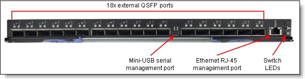
Figure 5. Front panel of the Flex System IB6131 InfiniBand Switch
The front panel contains the following components:
- LEDs that display the status of the module and the network:
- Green power LED indicates that the module has passed the power-on self-test (POST) with no critical faults and is operational.
- Identify LED: This blue LED can be used to identify the module physically by illuminating via the management software.
- The fault LED (switch error) indicates that the module has failed the POST or detected an operational fault.
- Eighteen external QSFP ports for 10 Gbps, 20 Gbps, 40 Gbps, or 56 Gbps connections to external InfiniBand devices.
- An InfiniBand physical link LED and an InfiniBand Tx/Rx LED for each external port on the module.
- One mini-USB RS-232 console port that provides an additional means to configure the switch module. This mini-USB-style connector enables the connection of a special serial cable (the cable is optional, and it is not included with the switch. See the Part number information section for details).
Network cabling requirements
The network cables that can be used with the switch are as follows:
- InfiniBand:
- 1 m, 3 m, or 5 m InfiniBand QDR or 3 m InfiniBand FDR copper QSFP cables listed in the Supported cables section.
- Other IBTA compliant QSFP cables
- External Ethernet RJ45 management port:
- Unshielded Twisted Pair (UTP) Category 6
- UTP Category 5e (100 meters (328.1 ft) maximum)
- UTP Category 5 (100 meters (328.1 ft) maximum)
- RS-232 serial cable: Console cable DB9-to-mini-USB or RJ45-to-mini-USB (nonstandard use of USB connector) that comes with optional Flex System Management Serial Access Cable, 90Y9338
Warranty
There is a 1-year, customer-replaceable unit (CRU) limited warranty. When installed in a chassis, these switches assume your system’s base warranty and any Lenovo Services upgrade.
Physical specifications
These are the approximate dimensions and weight of the switch:
- Height: 30 mm (1.2 inches)
- Width: 401 mm (15.8 inches)
- Depth: 317 mm (12.5 inches)
- Weight: 3.7 kg (8.1 lb)
Shipping dimensions and weight (approximate):
- Height: 114 mm (4.5 in)
- Width: 508 mm (20.0 in)
- Depth: 432 mm (17.0 in)
- Weight: 4.1 kg (9.1 lb)
Regulatory compliance
The module conforms to the following standards:
- Safety:
- US/Canada: cULus
- EU: IEC60950
- International: CB
- Environmental:
- Type I / II
- EU: IEC 60068?2?32: Fall Test
Popular configurations
Figure 6 shows the use of the Flex System IB6131 InfiniBand switches to route two InfiniBand FDR ports on the dual-port expansion card installed in slot 2 of the compute node. Each compute node has two InfiniBand ports, and two IB6131 switches are installed in bays 3 and 4 of the Enterprise Chassis. The connections between the adapter card and the modules are internal to the chassis. No cabling is needed.

Figure 6. Using IB6131 InfiniBand Switch with dual-port InfiniBand FDR adapter cards
The following table lists the solution components.
| Part number/machine type | Description | Quantity |
| 9532-x4x | Flex System x240 M5 with EN4172 2-port 10Gb Ethernet Adapter | 1 to 14 |
| 90Y3454 | Flex System IB6132 2-port FDR InfiniBand Adapter | 1 per server |
| 8721-A1x | Flex System Enterprise Chassis | 1 |
| 95Y3309 | Flex System Fabric EN4093R 10Gb Scalable Switch | 2 |
| 90Y3450 | Flex System IB6131 InfiniBand Switch | 2 |
| 90Y3462 | Flex System IB6131 InfiniBand Switch (FDR Upgrade) | 2 |
| 90Y3470 | 3m FDR InfiniBand Cable | Up to 18 per IB6131 switch |
Related product families
Product families related to this document are the following:
Trademarks
Lenovo and the Lenovo logo are trademarks or registered trademarks of Lenovo in the United States, other countries, or both. A current list of Lenovo trademarks is available on the Web at https://www.lenovo.com/us/en/legal/copytrade/.
The following terms are trademarks of Lenovo in the United States, other countries, or both:
Lenovo®
Flex System
Lenovo Services
System x®
Other company, product, or service names may be trademarks or service marks of others.


