

Top
Abstract
Lenovo Flex System is the next generation of blade technology with more performance and bandwidth and far more capability to consolidate and virtualize than previous systems. Flex System is anchored by the Flex System Enterprise Chassis which enables high-speed performance with integrated servers and networking. Furthermore, its flexible design can meet the needs of varying workloads with independently scalable IT resource pools for higher utilization and lower cost per workload.
How customers use Flex System Enterprise Chassis
Case Study: Furaco IT
Helping businesses harness the power of cloud computing:
How Furaco IT uses the Lenovo ThinkAgile MX platform to deliver customized private, public, and hybrid cloud services.
Change History
Changes in the January 2, 2024 update:
- The Flex System Enterprise Chassis is now withdrawn from marketing
Introduction
Flex System is the next generation of blade technology with more performance and bandwidth and far more capability to consolidate and virtualize than previous systems. Flex System is anchored by the Flex System Enterprise Chassis which enables high-speed performance with integrated servers and networking. Furthermore, its flexible design can meet the needs of varying workloads with independently scalable IT resource pools for higher utilization and lower cost per workload.
The Flex System Enterprise Chassis is shown in Figure 1.
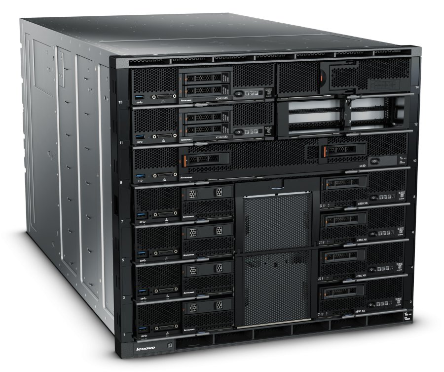
Figure 1. The Flex System Enterprise Chassis
Did you know?
In addition to the Flex System Enterprise Chassis, Lenovo also offers the Carrier-Grade Chassis for installations requiring tolerance to higher temperatures or for use in environments without filtered air. For information about the Carrier-Grade Chassis, see https://lenovopress.com/tips1285.
Key features
The Flex System Enterprise Chassis is a simple, integrated infrastructure platform that supports a mix of compute, storage, and networking resources to meet the demands of your applications. The solution is easily scalable with the addition of another chassis with the required nodes. With Lenovo XClarity Administrator, multiple chassis can be monitored from a single screen. This flexible 14 node, 10U chassis is designed for a simple deployment now and to scale to meet your needs in the future.
Flexibility and efficiency
The 14 bays in the chassis allow the installation of compute or management nodes, with networking modules in the rear. A single chassis or a group of chassis can be fully customized to the specific needs of the computing environment. IT can meet the needs of the business using a single system across multiple operating environments.
The system monitors and manages power usage on all major chassis components so you have total control over power consumption. AC power options can be configurable in either a single or three-phase power domain. The chassis supports N+N or N+1 redundant power supplies and an entirely passive mid-plane to meet your reliability needs. The power supplies are 80 PLUS Platinum-certified indicating high energy efficiency. The chassis design also optimizes cooling with cooling zones within the chassis. The system manages the fan modules based on node configuration within the chassis. So, the system can increase the speed of certain fan modules to cool potential hot spots, and use lower speeds for other fan modules where appropriate.
Easily scalable with simple administration
Because the Flex System Enterprise Chassis is an all-in-one solution, it is designed for growth from a single chassis to many. Adding compute, or networking capability is as simple as adding additional nodes or modules. Compute nodes and I/O modules connect to a midplane and are designed to be inserted or removed while the chassis is running. The use of the midplane means that the compute nodes and I/O modules do not need their own power cables and do not need network cables or transceivers to connect to each other within the chassis. These features make it easy to add or replace compute nodes and get them operational quickly.
The simple, highly integrated management system allows you to use the Chassis Management Modules integrated into each chassis to administer a single chassis, and the new Lenovo XClarity Administrator offers agent-free hardware management for compute nodes and networking.
Designed for multiple generations of technology
The Flex System Enterprise Chassis is designed to be the foundation of your IT infrastructure now and into the future. Compute performance requirements are always on the rise and networking demands continue to grow with rising bandwidth needs and a shrinking tolerance for latency. The chassis is designed to scale to meet the needs of your future workloads, offering the flexibility to support current and future innovations in compute, storage, and networking technology.
Locations of key components and connectors
The following figure shows the front of the Enterprise Chassis.
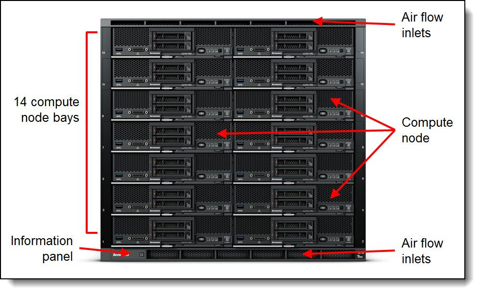
Figure 2. Front of the Flex System Enterprise Chassis
The following figure shows the rear of the Enterprise Chassis.
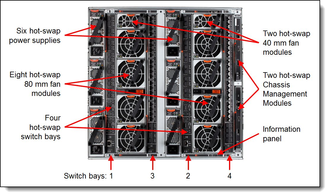
Figure 3. Rear of the Flex System Enterprise Chassis
Standard specifications
The following table lists the standard specifications.
Table 1. Standard specifications
| Components | Specification |
| Machine type | 8721 |
| Firmware | Chassis with first generation Chassis Management Module (68Y7030): IBM-signed firmware Chassis with Chassis Management Module 2 (00FJ669): Lenovo-signed firmware |
| Form factor | 10U rack-mounted unit. |
| Maximum number of compute nodes | 14 half-wide (single bay), seven full-wide (two bays), three double-height full-wide (four bays) or one quadruple-height full-wide (8 bays). Mixing is supported. |
| Chassis per 42U rack | Four. |
| Nodes per 42U rack | 56 half-wide, or 28 full-wide. |
| Management | Chassis Management Modules 2 (CMM2) modules provide chassis management. One or two CMM2s standard, depending on the model and the use of two provides redundancy. Earlier models of the Enterprise Chassis use the first generation CMM. The CMM2 interfaces with the integrated management module (IMM2) integrated in each compute node in the chassis. Optional Lenovo XClarity Administrator for hardware resource management with integrators to VMware vCenter and Microsoft System Center, including virtualization, networking, and storage management. Chassis with first generation CMM can be upgraded to CMM2 however CMM and CMM2 cannot be mixed. |
| I/O architecture | Up to eight lanes of I/O to an I/O adapter card, with each lane capable of up to 25 Gbps bandwidth. Up to 16 lanes of I/O to a half-wide node with two adapters. A wide variety of networking solutions, including Ethernet, Fibre Channel, Fibre Channel over Ethernet (FCoE), and InfiniBand. |
| Power supplies | Up to six power supplies that can provide N+N or N+1 redundant power. AC power supplies are 80 PLUS Platinum certified and provide over 94% efficiency at 50% load and 20% load. Each power supply contains two independently powered 40 mm cooling fan modules. All installed power supplies must be identical. |
| Fan modules | Ten fan modules (eight 80 mm fan modules and two 40 mm fan modules); Four 80 mm and two 40 mm fan modules standard. |
| Dimensions | Height: 440 mm (17.3 in) Width: 447 mm (17.6 in) Depth: 800 mm (31.5 in) (measured from front bezel to rear of chassis), 840 mm (33.1 in) (measured from node latch handle to the power supply handle) |
| Weight | Minimum configuration: 96.62 kg (213 lb) Maximum configuration: 220.45 kg (486 lb) |
| Sound level | 7.5 bels (declared) |
| Temperature | Operating air temperature 10°C to 40°C |
| Electrical power | AC Input power: 200 - 240 V ac (nominal), 50 or 60 Hz -48 V DC Input power: -48V to -60 V dc (nominal) Minimum configuration: 0.51 kVA (two power supplies) Maximum configuration: 13 kVA (six power supplies) |
| Power consumption | 12,900 watts maximum |
The following table lists what each standard model, Express model and TopSeller model includes. In addition, each model ships with:
- One C19 to C20 two-meter power cable for each power supply
- One Rack Mount Kit
Models
The Flex System Enterprise Chassis can be configured by using the Lenovo Data Center Solution Configurator (DCSC).
Configure-to-order (CTO) models are used to create models with factory-integrated server customizations. For CTO models, the base CTO models are listed in the following table.
- Model HC2 is for chassis orders with an FC5022 switch configured
- Model HC3 is for chassis orders without an FC5022 switch configured
| Description | Machine Type/Model |
|---|---|
| Flex System Enterprise Chassis with CMM2 - 3 year Warranty | 8721HC2 |
| Flex System Enterprise Chassis with CMM2 - 3 year Warranty (no FC5022 Fibre Channel switches) | 8721HC3 |
Preconfigured chassis models are also available as listed in the following table.
The following table lists the specifications of the standard Enterprise Chassis models.
| Model | Node bays |
CMM* (2 max) |
I/O bays (used / max) |
I/O modules included |
Power supplies (6 max) |
40mm fans (2 max) |
80mm fan (8 max) |
Console breakout cable |
| Standard models - World wide | ||||||||
| 8721-ALx | 14 | 1x CMM2 | 0 / 4 | None | 2x 2500W | 2 | 4 | 1 |
| Standard models - EMEA | ||||||||
| 8721-17A | 14 | 1x CMM2 | 0 / 4 | None | 2x 2500W | 2 | 4 | 1 |
| TopSeller models – North America | ||||||||
| 8721-E3U | 14 | 2x CMM2 | 2 / 4 | 2x SI4093# | 6x 2500W | 2 | 8 | 1 |
| 8721-E4U | 14 | 2x CMM2 | 2 / 4 | 2x CN4093# | 6x 2500W | 2 | 8 | 1 |
| 8721-E5U | 14 | 1x CMM2 | 0 / 4 | None | 2x 2500W | 2 | 4 | 1 |
| TopSeller models – Latin America & Brazil | ||||||||
| 8721-E3U | 14 | 2x CMM2 | 2 / 4 | 2x SI4093# | 6x 2500W | 2 | 8 | 1 |
| 8721-E4U | 14 | 2x CMM2 | 2 / 4 | 2x CN4093# | 6x 2500W | 2 | 8 | 1 |
* CMM1 = first generation Chassis Management Module (68Y7030), CMM2 = Chassis Management Module 2 (00FJ669)
† Model B1x includes two Flex System EN4023 10Gb Scalable Switches, 94Y5212 and two Flex System EN4023 10Gb Scalable Switch (FoD 3) upgrades, 47C9993. The FoD 3 upgrade enables FCoE on all active ports of the switches.
‡ Model B2x includes two Flex System EN4023 10Gb Scalable Switches, 94Y5212 and two Lenovo Flex System FC5022 24-port 16Gb SAN Scalable Switch, 00Y3324.
# Models E3U and E4U include two Flex System Fabric SI4093 System Interconnect Modules, 00FM518 or two Flex System Fabric CN4093 10Gb Converged Scalable Switches, 00FM510, respectively.
Supported compute nodes
The following table lists the compute nodes that are supported in the Flex System Enterprise Chassis. The table also lists the maximum number installable.
| Description | Machine type |
Firmware code base |
Supported in chassis
|
||
| 8721 with CMM1 (IBM signed) |
8721 with CMM2 (Lenovo signed) |
Maximum per chassis* |
|||
| Lenovo ThinkSystem servers | |||||
| ThinkSystem SN550 V2 | 7Z69 | Lenovo signed | No | Supported | 14 |
| ThinkSystem SN550 | 7X16 | Lenovo signed | No | Supported | 14 |
| ThinkSystem SN850 | 7X15 | Lenovo signed | No | Supported | 7 |
| Lenovo Flex System compute nodes | |||||
| Flex System x220 | 7906 | IBM signed | Supported | Supported | 14 |
| Flex System x222 | 7916 | IBM signed | Supported | Supported | 14 |
| Flex System x240 | 7162 | Lenovo signed | No | Supported | 14 |
| Flex System x240 | 8737 | IBM signed | Supported | Supported | 14 |
| Flex System x240 M5 (E5-2600 v3) | 9532 | Lenovo signed | Supported | Supported | 14 |
| Flex System x240 M5 (E5-2600 v4) | 9532 | Lenovo signed | No | Supported | 14 |
| Flex System x440 | 7917 | IBM signed | Supported | Supported | 7 |
| Flex System x440 | 7167 | Lenovo signed | Supported | Supported | 7 |
| Flex System x280 X6 | 7196 | Lenovo signed | No | Supported | 7 |
| Flex System x480 X6 | 7196 | Lenovo signed | Supported | Supported | 7 |
| Flex System x880 X6 | 7196 | Lenovo signed | Supported | Supported | 7 |
| Flex System x280 X6 | 7903 | IBM signed | Supported | Supported | 7 |
| Flex System x480 X6 | 7903 | IBM signed | Supported | Supported | 7 |
| Flex System x880 X6 | 7903 | IBM signed | Supported | Supported | 7 |
| Flex System Manager | 8731-A1x | IBM signed | Supported | Supported | 1** |
| IBM Power Systems servers | |||||
| Flex System p24L | 1457 | IBM signed | Supported | No | 14 |
| Flex System p260 | 7895-22X | IBM signed | Supported | No | 14 |
| Flex System p270 | 7954-24X | IBM signed | Supported | No | 14 |
| Flex System p460 | 7895-42X | IBM signed | Supported | No | 7 |
† The maximum number of compute nodes supported depends on a number of factors. See below.
** A single Flex System Manager appliance can manage up to 16 chassis
The actual number of compute nodes systems that can be powered on in a chassis depends on these factors:
- The TDP power rating for the processors that are installed in the compute nodes (x86 servers)
- The number of power supplies installed in the chassis
- The capacity of the power supplies installed in the chassis (2100 W or 2500 W)
- The power redundancy policy used in the chassis (N+1 or N+N)
For the x480 X6 or x880 X6, if two compute nodes are scaled together, then a maximum of 3 scaled complexes can be installed. For the x880 X6, if four compute nodes are scaled together, then a maximum of 1 scaled x880 X6 complexes can be installed. Other bays can be filled with other compute nodes.
The table in the Power Supplies section provides guidelines about what number of compute nodes can be powered on in the Enterprise Chassis, based on the type and number of power supplies installed.
See ServerProven® for the latest information about the supported servers:
http://www.lenovo.com/us/en/serverproven/flexsystem.shtml
Supported I/O modules
The Flex System Enterprise Chassis has four high-speed switch bays that are capable of supporting a variety of I/O architectures.
The switches are installed in switch bays in the rear of the Flex System Enterprise Chassis as shown in the following figure. Switches are normally installed in pairs (bays 1 & 2, and bays 3 & 4), because I/O adapter cards installed in the compute nodes route to two switch bays for performance and redundancy.
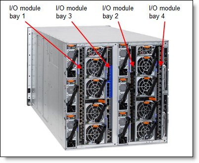
Figure 4. Location of the switch bays in the Flex System Enterprise Chassis
The following tables list the switches that are supported by the chassis.
Note: Some switches are withdrawn from marketing.
| Description | Part number | Firmware code base |
Supported in chassis
|
|
|---|---|---|---|---|
| 8721 with CMM (IBM signed) |
8721 with CMM2 (Lenovo signed) |
|||
| 25 Gb Ethernet module | ||||
| ThinkSystem NE2552E Flex Switch | 4SG7A08868 | Lenovo† | No | Supported |
| 10 Gb Ethernet modules | ||||
| EN4093R 10Gb Scalable Switch | 00FM514 | Lenovo† | No | Supported |
| SI4091 10Gb System Interconnect Module | 00FE327 | Lenovo† | No | Supported |
| SI4093 System Interconnect Module | 00FM518 | Lenovo† | No | Supported |
| EN4091 10Gb Ethernet Pass-thru | 88Y6043 | IBM | Supported | Supported |
† For these switches, IBM signed switch firmware is up to Version 7.x and Lenovo signed switch firmware is Version 8.x onwards
| Description | Part number | Firmware code base |
Supported in chassis
|
|
|---|---|---|---|---|
| 8721 with CMM (IBM signed) |
8721 with CMM2 (Lenovo signed) |
|||
| 40 Gb Ethernet module (withdrawn) | ||||
| EN6131 40Gb Ethernet Switch | 90Y9346* | Vendor | Supported | Supported |
| 10 Gb Ethernet modules (withdrawn) | ||||
| CN4093 10Gb Converged Scalable Switch | 00FM510* | Lenovo† | No | Supported |
| EN4093 10Gb Scalable Switch | 49Y4270* | IBM† | Supported | Supported |
| EN4093R 10Gb Scalable Switch | 95Y3309* | IBM† | Supported | Supported |
| CN4093 10Gb Converged Scalable Switch | 00D5823* | IBM† | Supported | Supported |
| SI4093 System Interconnect Module | 95Y3313* | IBM† | Supported | Supported |
| Cisco Nexus B22 Fabric Extender | 94Y5350* | Vendor | Supported | Supported |
| EN4023 10Gb Scalable Switch | 94Y5212* | Vendor | Supported | Supported |
| 1 Gb Ethernet switch (withdrawn) | ||||
| EN2092 1Gb Ethernet Scalable Switch | 49Y4294* | IBM† | Supported | Supported |
| Fibre Channel switches (withdrawn) | ||||
| FC5022 16Gb SAN Scalable Switch | 88Y6374 | Vendor | Supported | Supported |
| FC5022 24-port 16Gb SAN Scalable Switch | 00Y3324 | Vendor | Supported | Supported |
| FC5022 24-port 16Gb ESB SAN Scalable Switch | 90Y9356* | Vendor | Supported | Supported |
| FC3171 8Gb SAN Switch | 69Y1930* | Vendor | Supported | Supported |
| FC3171 8Gb SAN Pass-thru | 69Y1934* | Vendor | Supported | Supported |
| InfiniBand switches (withdrawn) | ||||
| IB6131 InfiniBand Switch (QDR/FDR) | 90Y3450* | Vendor | Supported | Supported |
* Withdrawn from marketing
† For these switches, IBM signed switch firmware is up to Version 7.x and Lenovo signed switch firmware is Version 8.x onwards
I/O architecture
Each half-wide compute node (such as the ThinkSystem SN550) has two adapter slots, and each full-wide compute node (such as the ThinkSystem SN850) has four adapter slots. The adapter slots in each compute node route through the chassis midplane to the switch bays. The architecture supports up to eight ports per adapter.
The following figure shows how two-port adapters are connected to switches installed in the chassis.
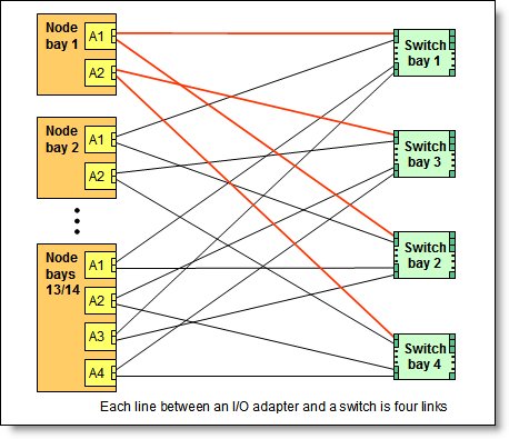
Figure 5. Logical layout of the interconnects between two-port I/O adapters and I/O modules
A four-port adapter doubles the connections between each adapter and switch pair (for example, a four-port adapter in A1 in each compute node routes two connections to switch 1 and two connections to switch 2).
The following figure shows how four-port adapters are connected to switches that are installed in the chassis.
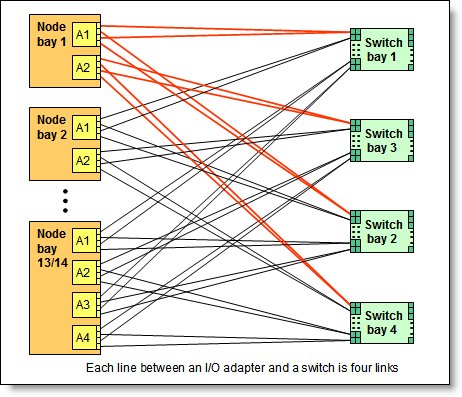
Figure 6. Logical layout of the inter-connections between four-port I/O adapters and I/O modules
The following table shows the connections between adapter slots in the compute nodes to the switch bays in the chassis.
Notes:
- To make use of all four ports of a four-port adapter across all blade servers, the switch must have 28 internal ports enabled, and two switches must be installed in the bays as indicated.
- To make use of six ports of a eight-port adapter across all blade servers, the switch must have 42 internal ports enabled, and two switches must be installed in the bays as indicated. Ports 7 and 8 of an eight-port adapter are reserved for future use. The chassis supports all eight ports, but there are no switches that are available that connect to these ports.
| I/O adapter slot in the server |
Port on the adapter* |
Corresponding I/O module bay
in the chassis |
|||
|---|---|---|---|---|---|
| Bay 1 | Bay 2 | Bay 3 | Bay 4 | ||
| Slot 1 | Port 1 | Yes | No | No | No |
| Port 2 | No | Yes | No | No | |
| Port 3 (for 4 & 8-port cards) | Yes | No | No | No | |
| Port 4 (for 4 & 8-port cards) | No | Yes | No | No | |
| Port 5 (for 8-port cards) | Yes | No | No | No | |
| Port 6 (for 8-port cards) | No | Yes | No | No | |
| Port 7 (for 8-port cards) | Yes | No | No | No | |
| Port 8 (for 8-port cards) | No | Yes | No | No | |
| Slot 2 | Port 1 | No | No | Yes | No |
| Port 2 | No | No | No | Yes | |
| Port 3 (for 4 & 8-port cards) | No | No | Yes | No | |
| Port 4 (for 4 & 8-port cards) | No | No | No | Yes | |
| Port 5 (for 8-port cards) | No | No | Yes | No | |
| Port 6 (for 8-port cards) | No | No | No | Yes | |
| Port 7 (for 8-port cards) | No | No | Yes | No | |
| Port 8 (for 8-port cards) | No | No | No | Yes | |
Chassis Management Module
The Chassis Management Module (CMM) provides single-chassis management in the Enterprise Chassis. The CMM is used to communicate with the integrated management module (IMM) controller in each compute node to provide system monitoring, event recording and alerts, and to manage the chassis, its devices, and the compute nodes.
The chassis has one CMM installed standard but supports two CMMs for redundancy. If one CMM fails, the second CMM can detect its inactivity and activate itself to take control of the system without any disruption. The CMM is central to the management of the chassis and is required in the Enterprise Chassis.
There are two versions of the Chassis Management Module available:
- Chassis Management Module 2 (00FJ669) -- contains a Trusted Platform Module (TPM) v2.0 chip and has a Lenovo-signed firmware codebase. This module is recommended for new installation.
- First generation Chassis Management Module (68Y7030) -- contains a Trusted Platform Module (TPM) v1.1 chip and has an IBM-signed firmware codebase
Standard and TopSeller models of the chassis contain either a CMM (68Y7030) or a CMM2 (00FJ669) as listed in Table 2. The selection of CMM determines which compute nodes and I/O modules are supported in the chassis. See Tables 3 and 4 respectively for details. You can replace a CMM with a CMM2, however mixing is not supported -- you cannot have a chassis with one CMM (68Y7030) and one CMM2 (00FJ669).
The following table shows the ordering information.
Table 8. Chassis Management Module
| Part number |
Feature codes** | Description | Standard / Maximum |
| 68Y7030* | A0TM / A0UE | Flex System Chassis Management Module | 1 / 2 |
| 00FJ669 | ASPT / ASQ8 | Flex System Chassis Management Module 2 | 1 / 2 |
* Withdrawn from marketing
** The first feature code corresponds to the base CMM installed in the chassis. The second feature code corresponds to the optional second CMM which provides redundancy.
The following figure shows the Chassis Management Module. See Figure 3 for the location of the CMM in the chassis.
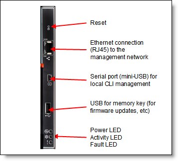
Figure 7. Chassis Management Module
The CMM provides these functions:
- Power control
- Fan management
- Chassis and compute node initialization
- Switch management
- Diagnostics: chassis, I/O options, and compute nodes
- Resource discovery and inventory management
- Resource alerts and monitoring management
- Chassis and compute node power management
- Security policy management
- Role-based access control
- Support for up to 84 local CMM user accounts
- Support for up to 32 simultaneous sessions
The CMM has the following connectors:
- USB connection. This connection can be used for insertion of a USB media key for tasks, such as firmware updates.
- 10/100/1000 Mbps RJ45 Ethernet connection to connect to a management network. The CMM can be managed via this Ethernet port.
- Serial port (mini-USB) for local command-line interface (CLI) management. Use serial cable 90Y9338 for connectivity.
The CMM has the following light-emitting diodes (LEDs) that provide the following information:
- Power-on LED
- Activity LED
- Error LED
- Ethernet port link and port activity LEDs
The CMM also incorporates a reset button, which, when pressed, resets the CMM back to its default condition. It has two functions, depending on how long the button is pressed:
- When pressed for less than 5 seconds, the CMM restarts.
- When pressed for more than 5 seconds (for example, 10 or 15 seconds), the CMM configuration is reset to the manufacturing defaults, and then the CMM restarts.
The CMM supports a web-based graphical user interface (GUI) that provides a way to perform CMM functions within a supported web browser. You can also perform management functions through the CMM command-line interface (CLI). Both the web-based GUI and the CLI are accessible via the single RJ45 Ethernet connector on the CMM or from any other system that is connected to the same (management) network.
The CMM has the following default static IPv4 address. By default, the CMM is configured to respond to Dynamic Host Configuration Protocol (DHCP) first before using its static IPv4 address:
- IP address: 192.168.70.100
- Subnet: 255.255.255.0
- User ID: USERID (all capital letters)
- Password: PASSW0RD (all capital letters, with a zero instead of the letter O)
The CMM does not have a fixed static IPv6 IP address, by default. Initial access to the CMM in an IPv6 environment can be performed by either using the IPv4 IP address or the IPv6 link-local address. The IPv6 link-local address is automatically generated based on the Media Access Control (MAC) address of the CMM.
The CMM is the key component enabling the integrated management network. Internally, the CMM has a multiple port L2 1Gigabit Ethernet switch with dedicated links to all 14 node bays, all four switch bays, and the second CMM, if installed. These connections are all point-to-point, ensuring dedicated bandwidth. The 1GbE links are full-duplex, fixed speed (not auto-negotiate) links. The 1 GbE management network is only accessible by each node's management controller (IMMv2 or FSP), each switch module's management interfaces, the CMM, and the Flex System Manager (FSM) management appliance. This design permits the separation of the management network from the data network.
The CMM has a high-security policy that is enabled by default, which means that the following policies are enabled by default:
- Strong password policies with automatic validation and verification checks
- Required update of the default passwords after the initial setup
- Only secure communication protocols, such as SSH and SSL. Unencrypted protocols, such as HTTP, Telnet, and SNMPv1, are disabled.
- Certificates to establish secure, trusted connections for applications that run on the management processors
Lenovo XClarity Administrator
Lenovo XClarity Administrator is centralized resource management solution aimed at reducing complexity, speeding response and enhancing availability of both Lenovo server systems and solutions.
Lenovo XClarity Administrator provides agent-free hardware management for System x rack servers and Flex System compute nodes and components, including the Chassis Management Module and Flex System I/O modules. The following figure shows the Lenovo XClarity Administrator interface, where both Flex System components and rack servers are being managed and can be seen on the dashboard.
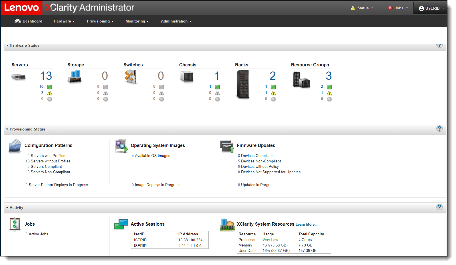
Figure 8. Lenovo XClarity Administrator dashboard
For information about Lenovo XClarity Administrator, see the Lenovo Press Product Guide:
http://lenovopress.com/tips1200
Power supplies
A maximum of six hot-swap power supplies can be installed in the Enterprise Chassis. In models where only two power supplies are standard, additional power supplies are orderable per the following table. All installed power supplies must be the same.
Note: The following power supplies are withdrawn from marketing:
- 2100W Power Module, 47C7633
- HVDC 2500W Power Module, 00AM765
| Description | Part number | Feature code* |
| Flex System Enterprise Chassis 2500W Power Module | 43W9049 | A0UC / A0UD |
| Flex System Enterprise Chassis -48V DC 2500W Power Module | 00FJ635 | A5VB / A5VC |
* Use the first feature code for the first 2 power supplies, and use the second feature code for any additional power supplies, up to a total of 6
Each AC power supply part number ships with one 2.0m (6.5 ft) 16A/100-250V, C19 to IEC 320-C20 rack power cable, feature 6292. Other supported AC line cords including three-way split line cords, are listed in the following table.
Table 10. Supported AC line cords
| Description | Part number | Feature code |
| 4.3m, 16A/208V, C19 to NEMA L6-20P (US) Line Cord | 40K9772 | 6275 |
| 2.5m, 16A/100-240V, C19 to IEC 320-C20 Rack Power Cable | 39Y7916 | 6252 |
| 2m, 16A/100-250V, C19 to IEC 320-C20 Rack Power Cable | None | 6292 |
| 4.3m, US/CAN, NEMA L15-30P - (3P+Gnd) to 3X IEC 320 C19 | 00D7192 | A2Y3 |
| 4.3m, EMEA/AP, IEC 309 32A (3P+N+Gnd) to 3X IEC 320 C19 | 00D7193 | A2Y4 |
| 4.3m, A/NZ, (PDL/Clipsal) 32A (3P+N+Gnd) to 3X IEC 320 C19 | 00D7194 | A2Y5 |
The -48V DC power supply operates at -48V to -60 V dc (nominal) and has a Molex 1060 Power Connector. The power supply ships with one 2.0m DC power cord (FRU part number 69Y1652)
The following figure shows the power supply and highlights the light-emitting diodes (LEDs).
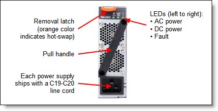
Figure 9. Power supply option
The AC power supplies are 80 PLUS Platinum-certified. The 2500W modules are 2500 Watts output rated at 200VAC to 208VAC (nominal), and 2750W at 220VAC to 240VAC (nominal). The power supply has an oversubscription rating of up to 3538 Watts output at 200VAC. The power supply operating range is 200-240 VAC. The power supplies also contain two dual independently powered 40mm cooling fan modules that are powered not from the power supply itself, but from the chassis midplane. The fan modules are variable speed and controlled by the chassis fan logic.
80 PLUS is a performance specification for power supplies used within servers and computers. To meet the 80 PLUS standard, the power supply must have an efficiency of 80% or greater, at 20%, 50%, and 100% of rated load with PF of .09 or greater. The standard has several grades, such as Bronze, Silver, Gold, and Platinum.
The chassis allows configurations of power supplies to give N+N or N+1 redundancy. A chassis can operate on only three power-supply units (PSUs) with no redundancy, but N+1 or N+N is advised. Three power supplies (or six with N+N redundancy) allow for a balanced three-phase configuration.
All power supply modules are combined into a single power domain within the chassis, which distributes power to each of the compute nodes, I/O modules, and ancillary components through the Enterprise Chassis midplane. The midplane is a highly reliable design with no active components. Each power supply is designed to provide fault isolation and is hot swappable.
In the case of the 2500W supplies, power monitoring of both the DC and AC signals allows the Chassis Management Module to accurately monitor the power supplies.
The following figure shows the compute node bay numbering (left) and power supply bay numbering (right).
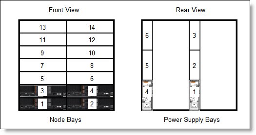
Figure 10. Power supply bay numbering
Fan modules
The Enterprise Chassis supports up to a total of ten hot-swap fan modules: two 40 mm (1.57 in) fan modules and eight 80 mm (3.14 in) fan modules. Fans are redundant and the chassis will continue to operate in the event that a fan module fails.
The two 40 mm fan modules distribute airflow to the I/O modules and chassis management modules. Both of these fan modules ship with the chassis. The 80 mm fan modules distribute airflow to the compute nodes through the chassis from front to rear. Each 80 mm fan module actually contains two 80 mm fan modules, back to back at each end of the module, which are counter-rotating. The following figure shows the 80 mm fan module.
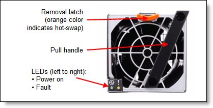
Figure 11. 80 mm fan module
Four 80 mm fan modules are installed standard in chassis model 8721-A1x and CTO orders. The maximum number of 80 mm fan modules that can be installed is eight. Ordering information is shown in the following table. When the modules are ordered as a part number, they are supplied as a pair. The feature codes is comprised of one fan.
Table 11. Fan module ordering information
| Description | Part number | Feature code |
| Flex System Enterprise Chassis 80mm Fan Module | 43W9078 (2 fan modules) |
A0UA (1 fan module) |
The 80 mm fan modules are populated, depending on the nodes installed. To support the base configuration and up to four nodes, chassis model 8721-A1x ships with four 80 mm fan modules and two 40 mm fan modules preinstalled. There are two cooling zones for the nodes: a left zone and a right zone. Fan modules must be installed in pairs as shown in the following figure. If there are insufficient fan modules for the number of nodes installed, the compute nodes might be throttled to balance heat generation and cooling capacity.
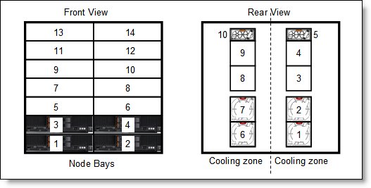
Figure 12. Fan module locations and cooling zones
The 40 mm fan modules are always required. Additional 80 mm fan modules are required as listed in the following table.
Table 12. 80 mm fan module requirements
| Description | 80 mm fan module requirements |
| Up to four half-wide compute nodes (node bays 1 - 4) | 4 fan modules (fan bays 1, 2, and 6, 7) |
| Up to eight half-wide compute nodes (node bays 1 - 8) | 6 fan modules (fan bays 1, 2, 3 and 6, 7, 8) |
| All 14 compute node bays (node bays 1 - 14) | 8 fan modules (fan bays 1, 2, 3, 4 and 6, 7, 8, 9) |
Physical specifications
Dimensions:
- Height: 440 mm (17.3 inches)
- Width: 447 mm (17.6 in)
- Depth, measured from front bezel to rear of chassis: 800 mm (31.5 in)
- Depth, measured from node latch handle to the power supply handle: 840 mm (33.1 in)
Weight:
- Minimum configuration: 96.62 kg (213 lb)
- Maximum configuration: 220.45 kg (486 lb)
Shipping dimensions (approximate):
- Height: 81 cm (32 in)
- Length: 102 cm (40 in)
- Width: 71 cm (24 in)
Supported environment
The Flex System Enterprise Chassis complies with ASHRAE Class A2 specifications.
The following environment is the supported operating environment.
Temperature:
- 0 - 914 m (0 - 3,000 ft): 10 - 40 °C (50 - 104 °F)
- 914 m - 3048 m (3,000 - 10,000 ft): The maximum ambient temperature drops 1 °C for every additional 178 m (584 ft) increase in altitude until the maximum temperature is 28 °C at 3,048 m (10,000 ft)
Relative humidity: 8% - 85%
Maximum altitude: 3,048 m (10,000 ft)
Electrical power:
- 200 - 240 V ac (nominal), 50 or 60 Hz
- Minimum configuration: 0.51 kVA (two power supplies)
- Maximum configuration: 13 kVA (six power supplies)
Power consumption: 12,900 watts maximum
Thermal output, full configuration - 12,900 watts (43,900 Btu/hr)
Acoustical noise emissions for Flex Chassis:
- 7.5 bels operating
- 7.5 bels idling
The noise emission level stated is the declared (upper limit) sound power level, in bels, for a random sample of machines. All measurements are made in accordance with ISO 7779 and reported in conformance with ISO 9296.
Warranty and Support
The Flex System Enterprise Chassis, 8721, has a three-year warranty.
The standard warranty terms are customer-replaceable unit (CRU) and onsite (for field-replaceable units FRUs only) with standard call center support during normal business hours and 9x5 Next Business Day Parts Delivered.
Lenovo’s additional support services provide a sophisticated, unified support structure for your data center, with an experience consistently ranked number one in customer satisfaction worldwide. Available offerings include:
- Premier Support
Premier Support provides a Lenovo-owned customer experience and delivers direct access to technicians skilled in hardware, software, and advanced troubleshooting, in addition to the following:
- Direct technician-to-technician access through a dedicated phone line
- 24x7x365 remote support
- Single point of contact service
- End to end case management
- Third-party collaborative software support
- Online case tools and live chat support
- On-demand remote system analysis
- Warranty Upgrade (Preconfigured Support)
Services are available to meet the on-site response time targets that match the criticality of your systems.
- 3, 4, or 5 years of service coverage
- 1-year or 2-year post-warranty extensions
- Foundation Service: 9x5 service coverage with next business day onsite response
- Essential Service: 24x7 service coverage with 4-hour onsite response or 24-hour committed repair (available only in select markets)
- Advanced Service: 24x7 service coverage with 2-hour onsite response or 6-hour committed repair (available only in select markets)
- Managed Services
Lenovo Managed Services provides continuous 24x7 remote monitoring (plus 24x7 call center availability) and proactive management of your data center using state-of-the-art tools, systems, and practices by a team of highly skilled and experienced Lenovo services professionals.
Quarterly reviews check error logs, verify firmware & OS device driver levels, and software as needed. We’ll also maintain records of latest patches, critical updates, and firmware levels, to ensure you systems are providing business value through optimized performance.
- Technical Account Management (TAM)
A Lenovo Technical Account Manager helps you optimize the operation of your data center based on a deep understanding of your business. You gain direct access to your Lenovo TAM, who serves as your single point of contact to expedite service requests, provide status updates, and furnish reports to track incidents over time. In addition, your TAM will help proactively make service recommendations and manage your service relationship with Lenovo to make certain your needs are met.
- Enterprise Server Software Support
Enterprise Software Support is an additional support service providing customers with software support on Microsoft, Red Hat, SUSE, and VMware applications and systems. Around the clock availability for critical problems plus unlimited calls and incidents helps customers address challenges fast, without incremental costs. Support staff can answer troubleshooting and diagnostic questions, address product comparability and interoperability issues, isolate causes of problems, report defects to software vendors, and more.
- Health Check
Having a trusted partner who can perform regular and detailed health checks is central to maintaining efficiency and ensuring that your systems and business are always running at their best. Health Check supports Lenovo-branded server, storage, and networking devices, as well as select Lenovo-supported products from other vendors that are sold by Lenovo or a Lenovo-Authorized Reseller.
Examples of region-specific warranty terms are second or longer business day parts delivery or parts-only base warranty.
If warranty terms and conditions include onsite labor for repair or replacement of parts, Lenovo will dispatch a service technician to the customer site to perform the replacement. Onsite labor under base warranty is limited to labor for replacement of parts that have been determined to be field-replaceable units (FRUs). Parts that are determined to be customer-replaceable units (CRUs) do not include onsite labor under base warranty.
If warranty terms include parts-only base warranty, Lenovo is responsible for delivering only replacement parts that are under base warranty (including FRUs) that will be sent to a requested location for self-service. Parts-only service does not include a service technician being dispatched onsite. Parts must be changed at customer’s own cost and labor and defective parts must be returned following the instructions supplied with the spare parts.
Lenovo Service offerings are region-specific. Not all preconfigured support and upgrade options are available in every region. For information about Lenovo service upgrade offerings that are available in your region, refer to the following resources:
- Service part numbers in Lenovo Data Center Solution Configurator (DCSC):
http://dcsc.lenovo.com/#/services - Lenovo Services Availability Locator
http://lenovolocator.com/
For service definitions, region-specific details, and service limitations, please refer to the following documents:
- Lenovo Statement of Limited Warranty for Infrastructure Solutions Group (ISG) Servers and System Storage
http://pcsupport.lenovo.com/us/en/solutions/ht503310 - Lenovo Data Center Services Agreement
http://support.lenovo.com/us/en/solutions/ht116628
Services
Lenovo Services is a dedicated partner to your success. Our goal is to reduce your capital outlays, mitigate your IT risks, and accelerate your time to productivity.
Note: Some service options may not be available in all markets or regions. For more information, go to https://www.lenovo.com/services. For information about Lenovo service upgrade offerings that are available in your region, contact your local Lenovo sales representative or business partner.
Here’s a more in-depth look at what we can do for you:
- Asset Recovery Services
Asset Recovery Services (ARS) helps customers recover the maximum value from their end-of-life equipment in a cost-effective and secure way. On top of simplifying the transition from old to new equipment, ARS mitigates environmental and data security risks associated with data center equipment disposal. Lenovo ARS is a cash-back solution for equipment based on its remaining market value, yielding maximum value from aging assets and lowering total cost of ownership for your customers. For more information, see the ARS page, https://lenovopress.com/lp1266-reduce-e-waste-and-grow-your-bottom-line-with-lenovo-ars.
- Assessment Services
An Assessment helps solve your IT challenges through an onsite, multi-day session with a Lenovo technology expert. We perform a tools-based assessment which provides a comprehensive and thorough review of a company's environment and technology systems. In addition to the technology based functional requirements, the consultant also discusses and records the non-functional business requirements, challenges, and constraints. Assessments help organizations like yours, no matter how large or small, get a better return on your IT investment and overcome challenges in the ever-changing technology landscape.
- Design Services
Professional Services consultants perform infrastructure design and implementation planning to support your strategy. The high-level architectures provided by the assessment service are turned into low level designs and wiring diagrams, which are reviewed and approved prior to implementation. The implementation plan will demonstrate an outcome-based proposal to provide business capabilities through infrastructure with a risk-mitigated project plan.
- Basic Hardware Installation
Lenovo experts can seamlessly manage the physical installation of your server, storage, or networking hardware. Working at a time convenient for you (business hours or off shift), the technician will unpack and inspect the systems on your site, install options, mount in a rack cabinet, connect to power and network, check and update firmware to the latest levels, verify operation, and dispose of the packaging, allowing your team to focus on other priorities.
- Deployment Services
When investing in new IT infrastructures, you need to ensure your business will see quick time to value with little to no disruption. Lenovo deployments are designed by development and engineering teams who know our Products & Solutions better than anyone else, and our technicians own the process from delivery to completion. Lenovo will conduct remote preparation and planning, configure & integrate systems, validate systems, verify and update appliance firmware, train on administrative tasks, and provide post-deployment documentation. Customer’s IT teams leverage our skills to enable IT staff to transform with higher level roles and tasks.
- Integration, Migration, and Expansion Services
Move existing physical & virtual workloads easily, or determine technical requirements to support increased workloads while maximizing performance. Includes tuning, validation, and documenting ongoing run processes. Leverage migration assessment planning documents to perform necessary migrations.
Regulatory compliance
The server conforms to the following standards:
- ASHRAE Class A2
- FCC - Verified to comply with Part 15 of the FCC Rules Class A
- Canada ICES-004, issue 3 Class A
- UL/IEC 60950-1
- CSA C22.2 No. 60950-1
- NOM-019
- Argentina IEC 60950-1
- Japan VCCI, Class A
- IEC 60950-1 (CB Certificate and CB Test Report)
- China CCC (GB4943); (GB9254, Class A); (GB17625.1)
- Taiwan BSMI CNS13438, Class A; CNS14336
- Australia/New Zealand AS/NZS CISPR 22, Class A
- Korea KN22, Class A, KN24
- Russia/GOST ME01, IEC 60950-1, GOST R 51318.22, GOST R 51318.249, GOST R 51317.3.2, GOST R 51317.3.3
- CE Mark (EN55022 Class A, EN60950-1, EN55024, EN61000-3-2, EN61000-3-3)
- CISPR 22, Class A
- TUV-GS (EN60950-1/IEC 60950-1, EK1-ITB2000)
Top-of-rack Ethernet switches
For enterprise-class installations with multiple Flex System Enterprise Chassis configurations, a top-of-rack Ethernet switch from Lenovo provides the necessary level of networking between racks of systems and the rest of your production network.
The following table lists the Ethernet LAN switches that are offered by Lenovo.
| Part number | Description |
|---|---|
| 1 Gb Ethernet Rack switches | |
| 7Y810011WW | Lenovo ThinkSystem NE0152T RackSwitch (Rear to Front) |
| 7Z320O11WW | Lenovo ThinkSystem NE0152TO RackSwitch (Rear to Front, ONIE) |
| 7159BAX | Lenovo RackSwitch G7028 (Rear to Front) |
| 7159CAX | Lenovo RackSwitch G7052 (Rear to Front) |
| 7159G52 | Lenovo RackSwitch G8052 (Rear to Front) |
| 7165H1X | Juniper EX2300-C PoE Switch |
| 7165H2X | Juniper EX2300-24p PoE Switch |
| 1 Gb Ethernet Campus switches | |
| 7Z340011WW | Lenovo CE0128TB Switch (3-Year Warranty) |
| 7Z360011WW | Lenovo CE0128TB Switch (Limited Lifetime Warranty) |
| 7Z340012WW | Lenovo CE0128PB Switch (3-Year Warranty) |
| 7Z360012WW | Lenovo CE0128PB Switch (Limited Lifetime Warranty) |
| 7Z350021WW | Lenovo CE0152TB Switch (3-Year Warranty) |
| 7Z370021WW | Lenovo CE0152TB Switch (Limited Lifetime Warranty) |
| 7Z350022WW | Lenovo CE0152PB Switch (3-Year Warranty) |
| 7Z370022WW | Lenovo CE0152PB Switch (Limited Lifetime Warranty) |
| 10 Gb Ethernet switches | |
| 7159A1X | Lenovo ThinkSystem NE1032 RackSwitch (Rear to Front) |
| 7159B1X | Lenovo ThinkSystem NE1032T RackSwitch (Rear to Front) |
| 7Z330O11WW | Lenovo ThinkSystem NE1064TO RackSwitch (Rear to Front, ONIE) |
| 7159C1X | Lenovo ThinkSystem NE1072T RackSwitch (Rear to Front) |
| 7159CRW | Lenovo RackSwitch G8272 (Rear to Front) |
| 7159GR6 | Lenovo RackSwitch G8296 (Rear to Front) |
| 7159BR6 | Lenovo RackSwitch G8124E (Rear to Front) |
| 25 Gb Ethernet switches | |
| 7159E1X | Lenovo ThinkSystem NE2572 RackSwitch (Rear to Front) |
| 7Z210O21WW | Lenovo ThinkSystem NE2572O RackSwitch (Rear to Front, ONIE) |
| 7Z330O21WW | Lenovo ThinkSystem NE2580O RackSwitch (Rear to Front, ONIE) |
| 100 Gb Ethernet switches | |
| 7159D1X | Lenovo ThinkSystem NE10032 RackSwitch (Rear to Front) |
| 7Z210O11WW | Lenovo ThinkSystem NE10032O RackSwitch (Rear to Front, ONIE) |
For more information, see the list of Product Guides in the following switch categories:
- 1 Gb Ethernet switches: http://lenovopress.com/networking/tor/1gb?rt=product-guide
- 10 Gb Ethernet switches: http://lenovopress.com/networking/tor/10gb?rt=product-guide
- 25 Gb Ethernet switches: http://lenovopress.com/networking/tor/25gb?rt=product-guide
- 40 Gb Ethernet switches: http://lenovopress.com/networking/tor/40gb?rt=product-guide
- 100 Gb Ethernet switches: https://lenovopress.com/networking/tor/100Gb?rt=product-guide
Fibre Channel SAN switches
Lenovo offers the ThinkSystem DB Series of Fibre Channel SAN switches for high-performance storage expansion. See the DB Series product guides for models and configuration options:
- ThinkSystem DB Series SAN Switches:
https://lenovopress.com/storage/switches/rack#rt=product-guide
Power distribution units
Power planning for an Flex System Enterprise Chassis is essential.
The Enterprise Chassis has a maximum of six power supplies installed. So, careful consideration must be given to providing the best power-optimized source. Both N+N and N+1 configurations are supported for maximum flexibility in power redundancy. Each AC power supply in the chassis has a 16A C20 three-pin socket and can be fed by a C19 power cable, from a suitable supply.
The chassis has the ability to accommodate a maximum of six power supplies, so it is possible to balance a three-phase power input into a single chassis or a group of chassis. The chassis power system is designed for efficiency using data center power consisting of three-phase, 60A Delta 200 VAC (North America) or three-phase 32A wye 380-415 VAC (international). The chassis can also be fed from single-phase 200 - 240VAC supplies, if required.
For further details, see the Flex System Enterprise Chassis Power Requirements Guide, available from:
https://support.lenovo.com/documents/LNVO-POWINF
Table 14. Power distribution units
| Part number | Description |
| Switched and monitored AC PDUs | |
| 46M4002 | 1U 9 C19/3 C13 Active Energy Manager DPI PDU |
| 46M4003 | 1U 9 C19/3 C13 Active Energy Manager 60A 3 Phase PDU |
| 46M4167 | 1U 9 C19/3 C13 Switched and Monitored 30A 3 Phase PDU |
| 46M4134 | 0U 12 C19/12 C13 Switched and Monitored 50A 3 Phase PDU |
| 46M4140 | 0U 12 C19/12 C13 50A 3 Phase PDU |
| Enterprise AC PDUs | |
| 71762MX | Ultra Density Enterprise PDU C19 PDU+ (WW) |
| 71762NX | Ultra Density Enterprise PDU C19 PDU (WW) |
| 71763MU | Ultra Density Enterprise PDU C19 3 phase 60A PDU+ (NA) |
| 71763NU | Ultra Density Enterprise PDU C19 3 phase 60A PDU (NA) |
| 39Y8923 | DPI 60A Three Phase C19 Enterprise PDU with IEC309 3P+G (208 V) fixed line cord |
| 39Y8948 | DPI Single Phase C19 Enterprise PDU without line cord |
| Front-end AC PDUs | |
| 39Y8934 | DPI 32amp/250V Front-end PDU with IEC 309 2P+Gnd connector |
| 39Y8938 | 30amp/125V Front-end PDU with NEMA L5-30P connector |
| 39Y8939 | 30amp/250V Front-end PDU with NEMA L6-30P connector |
| 39Y8940 | 60amp/250V Front-end PDU with IEC 309 60A 2P+N+Gnd connector |
| DC PDUs | |
| 44T0966 | 1U Higher Voltage DC PDU (240V/380V) |
Uninterruptible power supply units
The Flex System Enterprise Chassis supports attachments to the uninterruptible power supply units listed in the following table.
Table 15. Uninterruptible power supply units
| Part number | Description |
| 55946KX | RT6kVA 3U Rack or Tower UPS (200-240VAC) |
| 55948KX | RT8kVA 6U Rack or Tower UPS (200-240VAC) |
| 55949KX | RT11kVA 6U Rack or Tower UPS (200-240VAC) |
| 55948PX | RT8kVA 6U 3:1 Phase Rack or Tower UPS (380-415VAC) |
| 55949PX | RT11kVA 6U 3:1 Phase Rack or Tower UPS (380-415VAC) |
For more information, see the related Lenovo Press Product Guides in the UPS category:
https://lenovopress.com/servers/options/ups
Rack cabinets
The Flex System Enterprise Chassis is supported in the rack cabinets as listed in the following table. The suggested rack for Flex System is the 42U 1100 mm Enterprise V2 Deep Dynamic Rack, 93634PX.
Table 16. Rack cabinets
| Part number |
Feature code |
Rack cabinet | Supported |
| 93634PX | A1RC | 42U 1100 mm Enterprise V2 Deep Dynamic Rack | Recommended |
| 93634EX | A1RD | 42U 1100 mm Dynamic Enterprise V2 Expansion Rack | Recommended |
| 93634CX | A3GR | PureFlex System 42U Rack | Recommended |
| 93634DX | A3GS | PureFlex System 42U Expansion Rack | Recommended |
| 93634AX | A31F | PureFlex System 42U Rack | Recommended |
| 93634BX | A31G | PureFlex System 42U Expansion Rack | Recommended |
| 201886X | 2731 | 11U Office Enablement Kit | Yes* |
| 93072PX | 6690 | S2 25U Static Standard Rack | Yes |
| 93072RX | 1042 | S2 25U Dynamic Standard Rack | Yes |
| 93074RX | 1043 | S2 42U Standard Rack | Yes |
| 99564RX | 5629 | S2 42U Dynamic Standard Rack | Yes |
| 99564XX | 5631 | S2 42U Dynamic Standard Expansion Rack | Yes |
| 93084PX | 5621 | 42U Enterprise Rack | Yes |
| 93084EX | 5622 | 42U Enterprise Expansion Rack | Yes |
| 93604PX | 7649 | 42U 1200 mm Deep Dynamic Rack | Yes |
| 93604EX | 7650 | 42U 1200 mm Deep Dynamic Expansion Rack | Yes |
| 93614PX | 7651 | 42U 1200 mm Deep Static Rack | Yes |
| 93614EX | 7652 | 42U 1200 mm Deep Static Expansion Rack | Yes |
| 93624PX | 7653 | 47U 1200 mm Deep Static Rack | Yes |
| 93624EX | 7654 | 47U 1200 mm Deep Static Expansion Rack | Yes |
| 14102RX | 1047 | eServer™ Cluster 25U Rack | Yes |
| 14104RX | 1048 | Linux Cluster 42U Rack | Yes |
| 9306-900 | None | Netfinity® Rack | No |
| 9306-910 | None | Netfinity Rack | No |
| 9306-42P | None | Netfinity Enterprise Rack | No |
| 9306-42X | None | Netfinity Enterprise Rack Expansion Cabinet | No |
| 9306-200 | None | Netfinity NetBAY 22 | No |
* This Office Enablement kit is specifically designed for the BladeCenter S Chassis. The Flex System Enterprise Chassis can be installed in this kit with 1U of space remaining, however the noise generated by the chassis may not be acceptable for office use.
Lenovo Financial Services
Lenovo Financial Services reinforces Lenovo’s commitment to deliver pioneering products and services that are recognized for their quality, excellence, and trustworthiness. Lenovo Financial Services offers financing solutions and services that complement your technology solution anywhere in the world.
We are dedicated to delivering a positive finance experience for customers like you who want to maximize your purchase power by obtaining the technology you need today, protect against technology obsolescence, and preserve your capital for other uses.
We work with businesses, non-profit organizations, governments and educational institutions to finance their entire technology solution. We focus on making it easy to do business with us. Our highly experienced team of finance professionals operates in a work culture that emphasizes the importance of providing outstanding customer service. Our systems, processes and flexible policies support our goal of providing customers with a positive experience.
We finance your entire solution. Unlike others, we allow you to bundle everything you need from hardware and software to service contracts, installation costs, training fees, and sales tax. If you decide weeks or months later to add to your solution, we can consolidate everything into a single invoice.
Our Premier Client services provide large accounts with special handling services to ensure these complex transactions are serviced properly. As a premier client, you have a dedicated finance specialist who manages your account through its life, from first invoice through asset return or purchase. This specialist develops an in-depth understanding of your invoice and payment requirements. For you, this dedication provides a high-quality, easy, and positive financing experience.
For your region-specific offers, please ask your Lenovo sales representative or your technology provider about the use of Lenovo Financial Services. For more information, see the following Lenovo website:
https://www.lenovo.com/us/en/landingpage/lenovo-financial-services/
Related product families
Product families related to this document are the following:
Trademarks
Lenovo and the Lenovo logo are trademarks or registered trademarks of Lenovo in the United States, other countries, or both. A current list of Lenovo trademarks is available on the Web at https://www.lenovo.com/us/en/legal/copytrade/.
The following terms are trademarks of Lenovo in the United States, other countries, or both:
Lenovo®
BladeCenter®
Flex System
Lenovo Services
Netfinity®
RackSwitch
ServerProven®
System x®
ThinkSystem®
TopSeller
XClarity®
The following terms are trademarks of other companies:
Linux® is the trademark of Linus Torvalds in the U.S. and other countries.
Microsoft® is a trademark of Microsoft Corporation in the United States, other countries, or both.
Other company, product, or service names may be trademarks or service marks of others.


