

Top
Abstract
The Cisco Systems 4 Gb 20-port and 10-port Fibre Channel Switch Modules for BladeCenter provide high-performance end-to-end SAN solutions using 4 Gb Fibre Channel technology. These modules allow seamless integration of BladeCenter into existing Cisco SANs, and have functions equivalent to the Cisco MDS 9124 switch. These two switches have almost the same features and functions except for the number of activated ports: the 10-port switch has ten activated ports, and the 20-port switch has 20 activated ports.
Introduction
The Cisco Systems 4 Gb 20-port and 10-port Fibre Channel Switch Modules for BladeCenter provide high-performance end-to-end SAN solutions using 4 Gb Fibre Channel technology. These modules allow seamless integration of BladeCenter into existing Cisco SANs, and have functions equivalent to the Cisco MDS 9124 switch. These two switches have almost the same features and functions except for the number of activated ports: the 10-port switch has ten activated ports (seven internal ports and three external), and the 20-port switch has 20 activated ports (14 internal and six external).
Figure 1 shows the Cisco Systems 4 Gb Fibre Channel Switch Module.
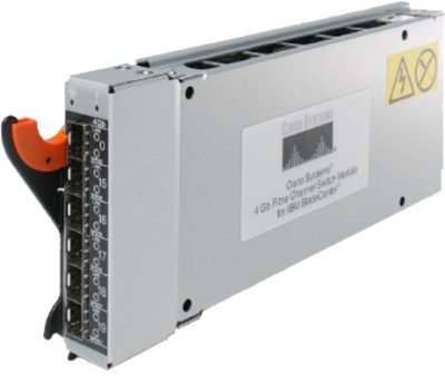
Figure 1. Cisco Systems 4 Gb Fibre Channel Switch Module
Did you know?
These Fibre Channel switching options integrate an enterprise fabric into the BladeCenter architecture, providing high-bandwidth connectivity. They offer high-performance, highly available storage area networks (SANs) at a competitive price, and are easy to set up and integrate into core or edge SAN configurations.
Part number information
Table 1 shows the part numbers to order these modules.
Table 1. Part numbers and feature codes for ordering
| Description | Part number | Feature code |
| Cisco Systems 4 Gb 20-port Fibre Channel Switch Module | 39Y9280 | 2983 |
| Cisco Systems 4 Gb 10-port Fibre Channel Switch Module | 39Y9284 | 2984 |
| Cisco Systems 10 port License Upgrade* | 39Y9290 | 4862 |
| Cisco Systems 4 Gb Short-wave Length SFP Module | 41Y8598 | 4864 |
| Cisco Systems 4 Gb Long-wave Length SFP Module (withdrawn from marketing) | 41Y8600 | Not available |
* For the 10-port switch only
The switch module part numbers include the following items:
- Cisco Systems 4 Gb 20-port or 10-port Fibre Channel Switch Module
- Installation Guide
- Safety Information
The switch does not ship with small form-factor pluggable (SFP) modules, and they must be ordered separately. Table 1 lists the transceivers that are supported.
Features
The 10-port and 20-port switch modules are identical hardware. The only difference is the number of ports that are active. The 20-port switch has all 14 internal ports active (one port for each server connection internal to the chassis) and all six external ports active. The 10-port switch has seven internal ports active (that is, only seven server connections) and three external ports active. You can enable the other ten ports by purchasing the Cisco Systems 10 port License Upgrade, part number 39Y9290.
The switch modules have the following features:
- Six external autosensing Fibre Channel ports that operate at 4, 2, or 1 Gbps (Gigabits per second)
- 14 internal autosensing Fibre Channel ports that operate at 4 or 2 Gbps
- Two internal full-duplex 100 Mbps Ethernet interfaces
- Power-on diagnostics and status reporting
- External ports can be configured as F_ports (fabric ports), FL_ports (fabric loop ports), or E_ports (expansion ports)
- Internal ports are configured as F_ports at 2 Gbps or 4 Gbps
- N-port ID Virtualization (NPIV) support
- VSAN support (up to 16 VSANs per switch)
- Advanced Traffic Management capabilities include:
- Virtual output queuing
- PortChannels supporting up to six external physical ISL links aggregated into one logical bundle
- Fabric-Shortest-Path-First (FSPF)-based multipathing for load balancing up to 16 equal-cost paths
- QoS for bandwidth management and traffic prioritization
- Access Control Lists
- Nondisruptive software upgrade
- Ability to support up to 239 domain IDs depending on configuration
- Optional small form-factor pluggable (SFP) modules
The following software features come with the switch modules:
- 20-port licensing (20-port version only)
- 10-port licensing (10-port version only)
- SMI-S and SNMP-based API
The switches support the following fabric management tools (all management connections go through the management module):
- Web interface
- Cisco MDS 9000 family command-line interface (CLI)
- Application program interface (API)
Supported BladeCenter chassis and expansion cards
The Cisco Systems 4 Gb Fibre Channel Switch Modules are supported in the BladeCenter chassis as listed in Table 2.
Table 2. BladeCenter chassis that support the Cisco Systems 4 Gb Fibre Channel Switch Modules
| I/O module | Part number | |||||||
| Cisco Systems 4 Gb 20-port Fibre Channel Switch Module | 39Y9280 | N | Y† | Y | Y* | Y* | Y | N |
| Cisco Systems 4 Gb 10-port Fibre Channel Switch Module | 39Y9284 | Y | Y† | Y | Y* | Y* | Y | N |
† The Advanced Management Module must be installed in the BladeCenter E chassis
* When the I/O module is installed in a BladeCenter T or HT chassis, the internal ports operate up to 2 Gbps, and the external ports operate at speeds up to 4 Gbps.
The Cisco Systems 4 Gb Fibre Channel Switch Modules support the expansion cards listed in Table 3. Table 3 also lists the chassis bays in which the switch module must be installed when used with each expansion card.
The BladeCenter chassis have the following bays:
- BladeCenter S, E, and T have four standard I/O bays (1, 2, 3, and 4)
- BladeCenter H has four standard I/O bays (1, 2, 3, and 4), two bridge bays (5 and 6), and four high-speed bays (7, 8, 9, and 10)
- BladeCenter HT has four standard I/O bays (1, 2, 3, and 4) and four high-speed bays (7, 8, 9, and 10)
The Cisco Systems 4 Gb Fibre Channel Switch Modules fit in a standard I/O bay (bays 1-6) and, with the addition of the Multi-Switch Interconnect Module (MSIM) in the BladeCenter H, can also fit in a high-speed I/O bay (bays 7-10). The Cisco Systems 4 Gb Fibre Channel Switch Modules are not supported with MSIM-HT in high-speed bays of the BladeCenter HT chassis.
Table 3. Expansion card support and Chassis I/O bay support
| I/O module | Part number | ||||||||||
| QLogic 4 Gb SFF FC Expansion Card | 26R0890 | N | N | Y | Y | N | N | N | N | N | N |
| QLogic 4 Gb Fibre Channel Expansion Card (CFFv) | 41Y8527 | N | N | Y | Y | N | N | N | N | N | N |
| Emulex 4 Gb Fibre Channel Expansion Card (CFFv) | 43W6859 | N | N | Y | Y | N | N | N | N | N | N |
| QLogic 4 Gb Fibre Channel Expansion Card (CIOv) | 46M6065 | N | N | Y | Y | N | N | N | N | N | N |
| QLogic Ethernet and 4 Gb Fibre Channel Expansion Card (CFFh) | 39Y9306 | N | N | N | N | N | N | N | Y | N | Y |
Note: When the I/O module is installed in a BladeCenter HT or BladeCenter T chassis, the internal ports operate up to 2 Gbps, and the external ports operate at speeds up to 4 Gbps.
Popular configurations
The Cisco Systems 4 Gb Fibre Channel Switch Modules can be used in various configurations.
Installation in standard switch bays
Figure 2 shows the Cisco Systems 4 Gb Fibre Channel Switch Module installed in two standard I/O bays in the BladeCenter chassis. The chassis is connected to the IBM System Storage DS3400. The servers in the chassis each have compatible CFFv or CIOv Fibre Channel expansion cards. The RAID functionality is provided by the external storage system.
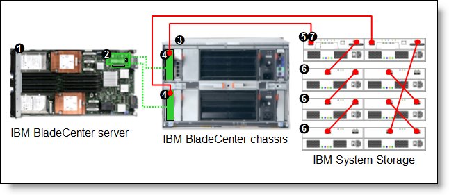
Figure 2. BladeCenter connected to an external IBM System Storage DS3400 storage solution
Table 4 lists the parts that are used in this configuration.
Table 4. Components used as shown in Figure 2
| Diagram reference | Part number / Machine type | Description | Quantity |
| Varies | BladeCenter HS22, HS21, or other supported server | 1 to 14 | |
| Varies | Supported CIOv or CFFv expansion card (see Table 3) | 1 per server | |
| Varies | Supported BladeCenter chassis | 1 | |
| 39Y9280 | Cisco Systems 4 Gb 20-port Fibre Channel Switch Module | 1 or 2 | |
| Not shown | 41Y8598 | Cisco Systems 4 Gb Short-wave Length SFP Module | Up to 6 |
| 1726-42X | IBM System Storage DS3400 (Dual Controller) | 1 | |
| 1727 | Optional IBM System Storage EXP3000 (Single or Dual ESM) | 1 to 3 | |
| Not shown | 39R6536 | DS3000 Partition Expansion License | 1 |
This configuration also requires cabling between the chassis and the storage server and between the storage server and expansion units. (The cable part numbers are not listed in the table.)
Installation in BladeCenter H high-speed switch bays
Figure 3 shows the Cisco Systems 4 Gb Fibre Channel Switch Module installed in MSIMs in the BladeCenter H chassis. The chassis is connected to the IBM System Storage DS3400. The servers in the chassis each have compatible CFFh Fibre Channel expansion cards. The RAID functionality is provided by the external storage system.
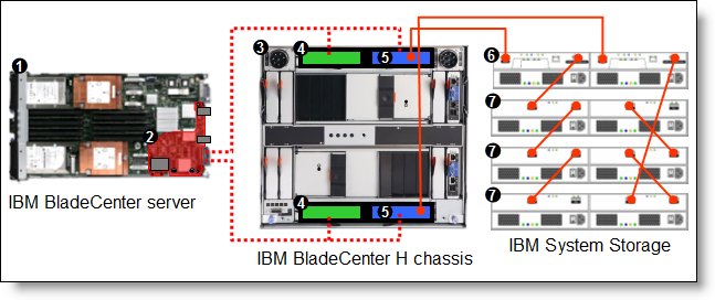
Figure 3. BladeCenter H connected to an external IBM System Storage DS3400 storage solution
Table 5 lists the parts that are used in this configuration.
Table 5. Components used as shown in Figure 3
| Diagram reference | Part number / machine type | Description | Quantity |
| Varies | BladeCenter HS22, HS21, or other supported server | 1 to 14 | |
| 39Y9306 | QLogic Ethernet and 4 Gb Fibre Channel Expansion Card (CFFh) | 1 per server | |
| 8852 | BladeCenter H chassis | 1 | |
| 39Y9314 | Multi-switch Interconnect Module | 1 or 2 | |
| 39Y9280 | Cisco Systems 4 Gb 20-port Fibre Channel Switch Module | 1 or 2 | |
| Not shown | 41Y8598 | Cisco Systems 4 Gb Short-wave Length SFP Module | Up to 12 |
| 1726-42X | IBM System Storage DS3400 (Dual Controller) | 1 | |
| 1727 | Optional: IBM System Storage EXP3000 (Single or Dual ESM) | 1 to 3 | |
| Not shown | 39R6536 | DS3000 Partition Expansion License | 1 |
This configuration also requires cabling between the chassis and the storage server and between the storage server and expansion units. (The cable part numbers are not listed in the table.)
Connectors and LEDs
The front panel of the Cisco Systems 4 Gb Fibre Channel Switch Module contains the following components, as shown in Figure 4:
- Information LEDs that display the status of the I/O module and its network connections.
- Six external Fibre Channel ports to connect Fibre Channel devices and switches. These ports are labeled 0, 15, 16, 17, 18, and 19 (from top to bottom) on the I/O module.
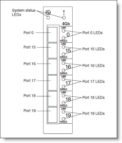
Figure 4. Front panel of the Cisco Systems 4 Gb Fibre Channel Switch Module
Table 6 lists the LEDs on the front panel and their meanings.
Table 6. LEDs on the front panel
| LED name | LED description |
| Power | This green LED is at the top left of the I/O module on the front panel and indicates that the module is working properly.
|
| Fault (!) (I/O module fault) | This amber LED is at the top right of the I/O module on the front panel. This LED indicates that the I/O module has a fault. Check the management module event log for details of the fault. |
| Port link | There are six green LEDs indicating connectivity and activity.
|
| Port speed | There are six green LEDs indicating link speed:
|
Operating environment
The environment must meet the following temperature and altitude requirements:
- Temperature: 10° to 35°C (50° to 95°F)
- Relative humidity: 8% to 80% non-condensing
Related product families
Product families related to this document are the following:
Trademarks
Lenovo and the Lenovo logo are trademarks or registered trademarks of Lenovo in the United States, other countries, or both. A current list of Lenovo trademarks is available on the Web at https://www.lenovo.com/us/en/legal/copytrade/.
The following terms are trademarks of Lenovo in the United States, other countries, or both:
Lenovo®
BladeCenter Interoperability Guide
BladeCenter®
Other company, product, or service names may be trademarks or service marks of others.


