

Top
Abstract
The family of IBM rack-based local console switches is designed to provide exceptional scalability and flexibility in managing data center environments. They give server administrators the power to centrally manage multiple servers from a single keyboard, mouse, and display. The CAT5-based switches work across all major platforms, are rack-mountable, and provide access for up to two simultaneous local users.
The options listed in this Product Guide are now withdrawn from marketing.
Introduction
The family of IBM rack-based local console switches is designed to provide exceptional scalability and flexibility in managing data center environments. They give server administrators the power to centrally manage multiple servers from a single keyboard, mouse, and display. The CAT5-based switches work across all major platforms, are rack-mountable, and provide access for up to two simultaneous local users.
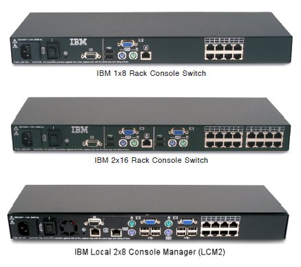
Figure 1. The IBM Rack Console Switches
Did you know?
Each of these keyboard-video-mouse (KVM) switches does more than just support the connection of eight or 16 direct-attach systems. With either daisy-chaining or tiered console switches, you can manage up to 128 systems from a single desktop using the 1x8 switch, up to 256 with the 2x16 switch, and up to 512 target systems with three tiers of LCM2 switches.
The LCM2 also supports a virtual media solution where you can connect a USB storage device directly to the LCM2 switch or leverage the integrated optical drive or USB pass-through on an attached 17" or 19" console kit and simply map the device directly to any servers attached to the switch with a Virtual Media Conversion Option (VCO). This solution eliminates the need to physically locate each system in the rack when transferring data during deployment or patching multiple servers.
The LCM2 also supports a virtual media solution where you can connect a USB storage device directly to the LCM2 switch or leverage the integrated optical drive or USB pass-through on an attached 17" or 19" console kit and simply map the device directly to any servers attached to the switch with a Virtual Media Conversion Option (VCO). This solution eliminates the need to physically locate each system in the rack when transferring data during deployment or patching multiple servers.
Part number information
Table 1. Ordering part numbers and feature codes
The IBM 1x8 Console Switch includes the following items:
The IBM 2x16 Console Switch includes the following items:
The IBM Local 2x8 Console Manager includes the following items:
Each of the Conversion Option parts listed in Table 1 ships with:
| Description | Part number | Feature code |
| IBM 1x8 Console Switch | 17353LX | Not applicable |
| IBM 2x16 Console Switch | 17354LX | Not applicable |
| IBM Local 2x8 Console Manager (LCM2) | 17351GX | Not applicable |
| IBM USB Conversion Option (UCO) | 43V6147 | 1735HC1 fc 3756 |
| IBM USB Conversion Option (UCO) 4-pack | 39M2895 | Not available |
| IBM Long KVM Conversion Option (KCO) | 39M2897 | 1735HC1 fc 3754 |
| IBM Virtual Media Conversion Option (VCO) | 39M2894 | 1735HC1 fc 3758 |
The IBM 1x8 Console Switch includes the following items:
- One 1x8 Console Switch
- Mounting hardware for EIA space for rack sidewall compartment
- One 1U filler panel
- One C13/C14 rack power cable
- Eight terminators for daisy-chaining configurations
- Installation publications and warranty
The IBM 2x16 Console Switch includes the following items:
- One 2x16 Console Switch
- Mounting hardware for EIA space for rack sidewall compartment
- One 1U filler panel
- One C13/C14 rack power cable
- 16 terminators for daisy-chaining configurations
- Installation publications and warranty
The IBM Local 2x8 Console Manager includes the following items:
- One 2x8 Console Switch
- Mounting hardware for EIA space for rack sidewall compartment
- One 1U filler panel
- One C13/C14 rack power cable
- Eight terminators for daisy-chaining configurations
- One 6 ft CAT-5 cable
- Installation publications and warranty
Each of the Conversion Option parts listed in Table 1 ships with:
- One Conversion Option
- One CAT-5 cable
- Installation publications and warranty
Features
The KVM console switches enable you to share one workspace (keyboard, mouse, and display) across many target systems. The target systems are connected to the console switch via CAT-5 cables and the appropriate conversion option at the target end. Conversion options are available with either USB or PS/2 connectors. In addition, multiple target systems can be daisy-chained together using CAT-5 cables, and then all connected to the console switch using the one cable, thereby eliminating a lot of cable clutter.
Table 2. Comparison of features
* The 1x8 and 2x16 console switches support the use of the Virtual Media Conversion Option (VCO) for connectivity, but they do not support the use of remote virtual media. The use of the VCO with these console switches represents a lower-cost alternative to the UCO if chaining is not required.
‡ 2048 target systems in a tiered configuration when front-ended with a Global Console Manager console switch.
† The Ethernet port of the LCM2 is for firmware updates only.
Number of local concurrent users:
The 1x8 and LCM2 console switches enable a single local user to access any attached servers. The 2x16 console switch enables two simultaneous users to access attached servers. With the 2x16 console switch, connections can be preemptive or cooperative. In preemptive mode, the connection between one local user and a target device is disconnected, without warning, if the second local user selects the same target device. In cooperative mode, the local user maintains the connection to a target device if another user selects the same target device. The way the keyboard and mouse are shared is configurable via the OSCAR interface.
Local user connections:
Local displays are connected to the console switch using VGA analog connections. Keyboard and mouse can be either PS/2-style connections or USB. Two USB ports are provided for mouse and keyboard connections. The LCM2 includes two additional USB ports for the attachment of devices such as optical drives or memory keys. These devices can be made available on remote target systems provided Virtual Media Conversion Options are used to connect to those target systems. Note, however, that the Virtual Media Conversion Option does not support chaining of target systems.
Target systems:
Each console switch has 8 or 16 target system ports (known as analog rack interface or ARI ports). These can be directly attached to systems with the appropriate USB or PS/2 conversion option connector on the end. These connections use standard CAT-5 cables. You can increase the number of connected target systems by two methods: chaining or a tiered arrangement of switches (more about these below). Both methods mean that each of the 8 or 16 ports will have multiple systems connected to it. You can mix connection methods.
Conversion Options:
These are cables-connector combinations that are connected between the CAT-5 cables from the console switches to the target systems. Figure 2 shows the three conversion option cables available for use with the console switches.
Shown on the left in Figure 2 are the KVM Conversion Option (KCO) with VGA and PS/2-style mouse and keyboard connections, and the USB Conversion Option (UCO) with VGA and USB connections.
The Virtual Media Conversion Option shown on the right in Figure 2 supports the virtual media capability of the LCM2; however, it does not support chaining. More about virtual media in the heading Virtual Media later in this document.
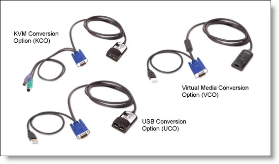
Figure 2. IBM KVM Conversion Option, KCO (top) and IBM USB Conversion Option, UCO (bottom)
The built-in memory of each connection option helps simplify configuration by assigning and retaining unique server identification codes for each attached server. This integrated intelligence enhances security and helps prevent unauthorized access to a server through cable manipulation. The connection option is powered directly from the server, providing Keep Alive functionality even if the server is not powered on.
OSCAR user interface:
The On-Screen Configuration and Activity Reporting (OSCAR) user interface is the way users access the target systems. Accessible by default via the Print Screen key, it has menus to configure the switching system and to select computers. You can list target devices by unique name, electronic ID, or port number.
Security:
All of these local console switches support the use of a password for access to the target systems. The OSCAR interface enables you to configure a screen saver password; you are prompted for the password after a configurable time-out, when the user logs out, or when the switch is powered on. This prevents unauthorized access to the target systems.
In addition, the OSCAR interface on the 1x8 and 2x16 console switches lets you configure up to four user accounts, and you can specify which target systems each of those accounts can access.
Firmware updates:
All of these local console switches can have their firmware updated. The 1x8 and 2x16 console switches enable the updating of firmware via the serial port. The LCM2 lets you update the firmware using a serial port console and a TFTP server using the Ethernet connection. With all of these console switches, once the console switch firmware is updated, the firmware of the Conversion Options can be performed via the OSCAR user interface, either individually or all Conversion Options can all be upgrade simultaneously. Automatic updates of the Conversion Options is also possible.
Table 2. Comparison of features
| Feature | IBM 1x8 Console Switch | IBM 2x16 Console Switch | IBM 2x8 LCM2 |
| Number of local concurrent users | 1 | 2 | 2 |
| Local user connections - KVM | VGA + PS/2 or USB | VGA + PS/2 or USB | VGA + PS/2 or USB |
| Local user connections - extra USB | No | No | Yes (2) |
| Remote user connections | Not available | Not available | Not available |
| Maximum number of target systems - Direct (ARI ports) | 8 | 16 | 8 |
| Maximum number of target systems - Daisy-chained | 128 | 256 | 128 |
| Maximum number of target systems - Tiered configuration | 128 | 256 | 512 / 2048‡ |
| Maximum video resolution | 1280 x 1024 @ 75 Hz | 1280 x 1024 @ 75 Hz | 1280 x 1024 @ 75 Hz |
| Support for USB Conversion Option, UCO (43V6147 and 39M2895) | Yes | Yes | Yes |
| Support for KVM (PS/2) Conversion Option, KCO (39M2897) | Yes | Yes | Yes |
| Support for Virtual Media Conversion Option, VCO (39M2894) | Yes* | Yes* | Yes |
| Virtual media | No | No | Yes |
| OSCAR user interface | Yes | Yes | Yes |
| Password protection | Yes | Yes | Yes |
| Serial port | Yes | Yes | Yes |
| Ethernet port | No | No | Yes† |
| Firmware upgrades to the console switch | Via serial port | Via serial port | Via serial & Ethernet |
| Firmware upgrades to the COs | Via OSCAR interface | Via OSCAR interface | Via OSCAR interface |
| Input power | 100-240V, 50/60 Hz 12.5 W consumption, 40 W max |
100-240V, 50/60 Hz 12.5 W consumption, 40 W max |
100-240V, 50/60 Hz 12.5 W consumption, 40 W max |
‡ 2048 target systems in a tiered configuration when front-ended with a Global Console Manager console switch.
† The Ethernet port of the LCM2 is for firmware updates only.
Number of local concurrent users:
The 1x8 and LCM2 console switches enable a single local user to access any attached servers. The 2x16 console switch enables two simultaneous users to access attached servers. With the 2x16 console switch, connections can be preemptive or cooperative. In preemptive mode, the connection between one local user and a target device is disconnected, without warning, if the second local user selects the same target device. In cooperative mode, the local user maintains the connection to a target device if another user selects the same target device. The way the keyboard and mouse are shared is configurable via the OSCAR interface.
Local user connections:
Local displays are connected to the console switch using VGA analog connections. Keyboard and mouse can be either PS/2-style connections or USB. Two USB ports are provided for mouse and keyboard connections. The LCM2 includes two additional USB ports for the attachment of devices such as optical drives or memory keys. These devices can be made available on remote target systems provided Virtual Media Conversion Options are used to connect to those target systems. Note, however, that the Virtual Media Conversion Option does not support chaining of target systems.
Target systems:
Each console switch has 8 or 16 target system ports (known as analog rack interface or ARI ports). These can be directly attached to systems with the appropriate USB or PS/2 conversion option connector on the end. These connections use standard CAT-5 cables. You can increase the number of connected target systems by two methods: chaining or a tiered arrangement of switches (more about these below). Both methods mean that each of the 8 or 16 ports will have multiple systems connected to it. You can mix connection methods.
Conversion Options:
These are cables-connector combinations that are connected between the CAT-5 cables from the console switches to the target systems. Figure 2 shows the three conversion option cables available for use with the console switches.
Shown on the left in Figure 2 are the KVM Conversion Option (KCO) with VGA and PS/2-style mouse and keyboard connections, and the USB Conversion Option (UCO) with VGA and USB connections.
The Virtual Media Conversion Option shown on the right in Figure 2 supports the virtual media capability of the LCM2; however, it does not support chaining. More about virtual media in the heading Virtual Media later in this document.
Figure 2. IBM KVM Conversion Option, KCO (top) and IBM USB Conversion Option, UCO (bottom)
The built-in memory of each connection option helps simplify configuration by assigning and retaining unique server identification codes for each attached server. This integrated intelligence enhances security and helps prevent unauthorized access to a server through cable manipulation. The connection option is powered directly from the server, providing Keep Alive functionality even if the server is not powered on.
OSCAR user interface:
The On-Screen Configuration and Activity Reporting (OSCAR) user interface is the way users access the target systems. Accessible by default via the Print Screen key, it has menus to configure the switching system and to select computers. You can list target devices by unique name, electronic ID, or port number.
Security:
All of these local console switches support the use of a password for access to the target systems. The OSCAR interface enables you to configure a screen saver password; you are prompted for the password after a configurable time-out, when the user logs out, or when the switch is powered on. This prevents unauthorized access to the target systems.
In addition, the OSCAR interface on the 1x8 and 2x16 console switches lets you configure up to four user accounts, and you can specify which target systems each of those accounts can access.
Firmware updates:
All of these local console switches can have their firmware updated. The 1x8 and 2x16 console switches enable the updating of firmware via the serial port. The LCM2 lets you update the firmware using a serial port console and a TFTP server using the Ethernet connection. With all of these console switches, once the console switch firmware is updated, the firmware of the Conversion Options can be performed via the OSCAR user interface, either individually or all Conversion Options can all be upgrade simultaneously. Automatic updates of the Conversion Options is also possible.
Connections
Figure 3 shows the connections on the 2x16 console switch. The 1x8 console switch has identical connections except it only has eight ARI ports, whereas the 2x16 has 16 ARI ports.
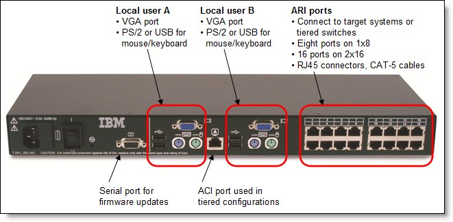
Figure 3. Connections on the 2x16 Console Switch
Figure 4 shows the connections on the LCM2 console switch. The LCM2 offers two extra USB ports for each local user for the virtual media feature plus an Ethernet port for firmware updates.
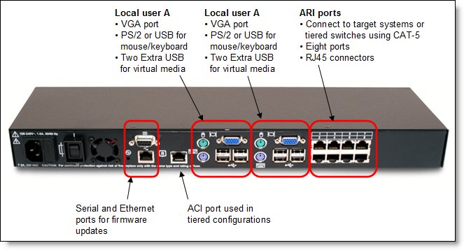
Figure 4. Connections on the LCM2 Console Switch
Figure 3. Connections on the 2x16 Console Switch
Figure 4 shows the connections on the LCM2 console switch. The LCM2 offers two extra USB ports for each local user for the virtual media feature plus an Ethernet port for firmware updates.
Figure 4. Connections on the LCM2 Console Switch
Chaining
IBM’s cable chaining solution enables users to manage a "daisy chain" of multiple servers through a single connection to the console switch, replacing many long cables with just a few short ones, simplifying rack management, helping lower cabling cost and reducing setup, diagnostic, and maintenance times. The daisy-chain connectivity has the added advantage of thin, flexible, industry-standard CAT5 cabling and standard RJ-45 connectors, eliminating the need for one-to-one, dedicated cable connections between KVM switch ports and managed devices. This cable chaining solution allows up to 16 target systems to be chained together and connected to one port on the switch.
Figure 5 shows an example of chaining three target systems from one port on the console switch. Each conversion option part number includes a CAT-5 cable to connect it to either the console switch or its neighbor conversion option. The console switch includes the terminator needed at the end of the daisy chain.
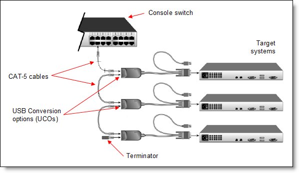
Figure 5. Chaining using USB Conversion Options
Figure 5 shows an example of chaining three target systems from one port on the console switch. Each conversion option part number includes a CAT-5 cable to connect it to either the console switch or its neighbor conversion option. The console switch includes the terminator needed at the end of the daisy chain.
Figure 5. Chaining using USB Conversion Options
Tiered consoles
You can tier multiple rack console switches to enable access to additional servers. In a tiered system, an ARI port on the main rack console switch connects to the ACI port of a tiered rack console switch (see Figure 3 for locations of these ports). Consider a tiered configuration if you want to manage servers connected to multiple switches from one central location. For example, you could have a primary 2x16 console switch with 16 switches tiered underneath it that all have servers chained on their ports.
Figure 6 shows an example of tiered consoles.
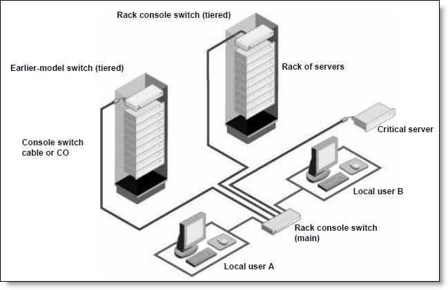
Figure 6. Tiered consoles
Maximum configurations are as follows:
Figure 6 shows an example of tiered consoles.
Figure 6. Tiered consoles
Maximum configurations are as follows:
- The 1x8 Console Switch can scale to support up to a total of 128 target systems by connecting additional console switches to each of the 8 ARI ports on the 1x8 switch. Only one level of tiering is supported.
- The 2x16 Console Switch can scale to support up to a total of 256 target systems by connecting additional console switches to each of the 16 ARI ports on the 1x8 switch. Only one level of tiering is supported.
- The LCM2 Console Switch can scale to support up to a total of 512 target systems by connecting additional console switches to each of the 8 ARI ports on the LCM2 switch. One, two, or three levels of tiering are supported.
- When using the IBM GCM console switch as the primary switch in a tiered environment, the KVM switching system can scale to support 2048 target systems
Virtual Media
The LCM2 supports virtual media when the target systems are connected using the Virtual Media Conversion Option (VCO), part number 39M2894. You can use virtual media support to connect USB 2.0 media devices to the console switch using one of the four USB ports and make those devices available to any connected system. With this feature, you can install software; install, upgrade, or recover the operating system; update the BIOS code; or boot the target system from a USB drive.
Control of how the USB device is connected to the target system is managed through the OSCAR user interface. OSCAR presents the following configuration options:
Note that USB ports are assigned to a single virtual media session and cannot be independently mapped. This means you cannot map one USB device to one target system and another USB device to another target system.
Control of how the USB device is connected to the target system is managed through the OSCAR user interface. OSCAR presents the following configuration options:
- Locked or Unlocked: In Locked mode, when the user is disconnected from a target system, the virtual media is also disconnected. If Unlocked is selected, then when the user disconnects, the media device is still seen by the target system.
- Reserved: By checking this option in the OSCAR user interface, the virtual media connection can be accessed only by your user name and no other user can connect to the virtual media connection.
- CD-ROM: Establishes a virtual CD connection to the target system.
- Mass Storage: Establishes a virtual mass-storage device connection to the target system.
- Write Access: With this option, you can specify whether the target system can write to the USB device (assuming it is writable).
Note that USB ports are assigned to a single virtual media session and cannot be independently mapped. This means you cannot map one USB device to one target system and another USB device to another target system.
Physical specifications
1x8 and 2x16 console switches:
Height: 43 mm (1.7 inches)
Width: 432 mm (17 inches)
Depth: 165 mm (6.5 inches)
Weight: 3.6 kg (8 lb)
LCM2 console switch:
Height: 43 mm (1.7 inches)
Width: 432 mm (17 inches)
Depth: 203 mm (8 inches)
Weight: 2.6 kg (5.75 lb)
Height: 43 mm (1.7 inches)
Width: 432 mm (17 inches)
Depth: 165 mm (6.5 inches)
Weight: 3.6 kg (8 lb)
LCM2 console switch:
Height: 43 mm (1.7 inches)
Width: 432 mm (17 inches)
Depth: 203 mm (8 inches)
Weight: 2.6 kg (5.75 lb)
Warranty
Each console switch has a three-year limited warranty when installed in an IBM rack or used with IBM servers.
Supported systems
The console switches are supported connected to the IBM BladeCenter chassis listed in Table 3.
Table 3. Supported IBM BladeCenter chassis
The console switches are supported connected to the IBM System x servers listed in Table 4.
Table 4. Supported IBM System x servers
See the IBM ServerProven Web site for the latest compatibility information: http://ibm.com/servers/eserver/serverproven/compat/us/.
Table 3. Supported IBM BladeCenter chassis
|
I/O module |
Part number |
|
|
|
|
|
|
IBM 1x8 Console Switch |
17353LX |
Y |
Y |
Y |
Y |
Y |
|
IBM 2x16 Console Switch |
17354LX |
Y |
Y |
Y |
Y |
Y |
|
IBM Local 2x8 Console Manager (LCM2) |
17351GX |
Y |
Y |
Y |
N |
Y |
The console switches are supported connected to the IBM System x servers listed in Table 4.
Table 4. Supported IBM System x servers
|
1x8 Console Switch |
N |
Y |
Y |
Y |
Y |
Y |
Y |
N |
Y |
Y |
Y |
Y |
Y |
N |
Y |
Y |
Y |
Y |
Y |
|
2x16 Console Switch |
N |
Y |
Y |
Y |
Y |
Y |
Y |
N |
Y |
Y |
Y |
Y |
Y |
N |
Y |
Y |
Y |
Y |
Y |
|
LCM2 Console Switch |
Y |
Y |
Y |
Y |
Y |
Y |
Y |
N |
Y |
Y |
Y |
Y |
Y |
N |
Y |
Y |
Y |
Y |
Y |
See the IBM ServerProven Web site for the latest compatibility information: http://ibm.com/servers/eserver/serverproven/compat/us/.
Related product families
Product families related to this document are the following:
Trademarks
Lenovo and the Lenovo logo are trademarks or registered trademarks of Lenovo in the United States, other countries, or both. A current list of Lenovo trademarks is available on the Web at https://www.lenovo.com/us/en/legal/copytrade/.
The following terms are trademarks of Lenovo in the United States, other countries, or both:
Lenovo®
BladeCenter®
ServerProven®
System x®
Other company, product, or service names may be trademarks or service marks of others.


