

Top
Author
Updated
16 Apr 2024Form Number
LP1608PDF size
152 pages, 6.2 MBSubscribed to LP1608.
Thank you for your feedback.
Download PDF
* Only available in selected markets
Table of Contents
- Introduction
- Did you know?
- Key features
- Comparing the SR665 V3 to the SR665
- Components and connectors
- System architecture
- Standard specifications
- Models
- Processors
- Memory options
- Internal storage
- Controllers for internal storage
- Internal drive options
- Internal backup units
- Optical drives
- I/O expansion
- Network adapters
- Fibre Channel host bus adapters
- SAS adapters for external storage
- Flash storage adapters
- GPU adapters
- Cooling
- Power supplies
- Systems management
- Security
- Rack installation
- Operating system support
- Physical and electrical specifications
- Operating environment
- Water infrastructure for the Lenovo Neptune Processor DWC Module
- RM100 In-Rack Coolant Distribution Unit
- Warranty and Support
- Services
- Regulatory compliance
- External drive enclosures
- External storage systems
- External backup units
- Fibre Channel SAN switches
- Uninterruptible power supply units
- Power distribution units
- Rack cabinets
- KVM console options
- Lenovo Financial Services
- Seller training courses
- Related publications and links
- Related product families
- Trademarks
Abstract
The Lenovo ThinkSystem SR665 V3 is a 2-socket 2U server that features the AMD EPYC 9004 "Genoa" family of processors. With up to 128 cores per processor and support for the new PCIe 5.0 standard for I/O, the SR665 V3 offers the ultimate in two-socket server performance in a 2U form factor.
This product guide provides essential pre-sales information to understand the ThinkSystem SR665 V3 server, its key features and specifications, components and options, and configuration guidelines. This guide is intended for technical specialists, sales specialists, sales engineers, IT architects, and other IT professionals who want to learn more about the SR665 V3 and consider its use in IT solutions.
Change History
Changes in the April 16, 2024 update:
- New support for open-loop liquid cooling with the Lenovo Neptune Processor DWC Module:
Introduction
The Lenovo ThinkSystem SR665 V3 is a 2-socket 2U server that features the AMD EPYC 9004 "Genoa" family of processors. With up to 128 cores per processor and support for the new PCIe 5.0 standard for I/O, the SR665 V3 offers the ultimate in two-socket server performance in a 2U form factor. The server is ideal for dense workloads that can take advantage of GPU processing and high-performance NVMe drives.
Suggested uses: Inference, virtualization, VDI, HPC, Hyperconverged infrastructure
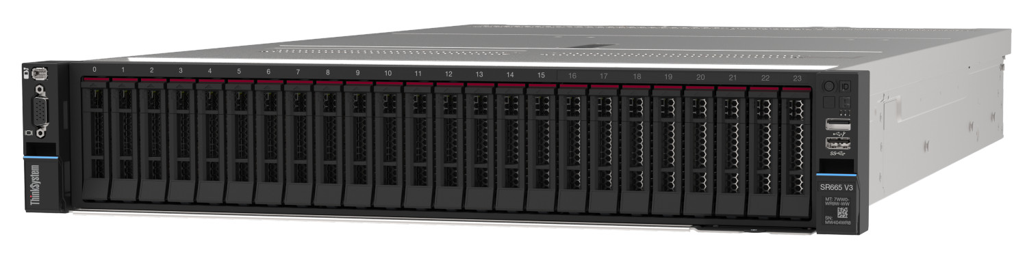
Figure 1. Lenovo ThinkSystem SR665 V3
Did you know?
The SR665 V3 server is a very configuration-rich offering, supporting 30 different drive bay configurations in the front, middle and rear of the server and 6 different slot configurations at the rear of the server. This level of flexibility ensures that you can configure the server exactly the way your workload requires.
Key features
Combining performance and flexibility, the SR665 V3 server is a great choice for enterprises of all sizes. The server offers a broad selection of drive and slot configurations and offers high performance features that industries such as finance, healthcare and telco need. Outstanding reliability, availability, and serviceability (RAS) and high-efficiency design can improve your business environment and can help save operational costs.
Scalability and performance
The following features boost performance, improve scalability and reduce costs:
- Supports one or two fourth-generation AMD EPYC 9004 processors
- Up to 128 cores and 256 threads
- Core speed of up to 4.1 GHz
- TDP rating of up to 360 W
- Support for DDR5 memory DIMMs to maximize the performance of the memory subsystem:
- Up to 24 DDR5 memory DIMMs, 12 DIMMs per processor
- 12 memory channels per processor (1 DIMM per channel)
- DIMM speeds up to 4800 MHz
- Using 256GB 3DS RDIMMs, the server supports up to 6TB of system memory
- Supports up to eight single-width GPUs or three double-wide GPUs, for substantial processing power in a 2U system.
- The server is Compute Express Link (CXL) v1.1 Ready. With CXL 1.1 for next-generation workloads, you can reduce compute latency in the data center and lower TCO. CXL is a protocol that runs across the standard PCIe physical layer and can support both standard PCIe devices as well as CXL devices on the same link.
- Supports up to 40x 2.5-inch hot-swap drive bays, by using combinations of front-accessible (up to 24 bays), mid bays (8 bays) and rear-accessible (8 bays).
- Supports 20x 3.5-inch drive bays for lower-cost high-capacity HDD storage. 2.5-inch and 3.5-inch drive bays can be mixed if desired.
- Supports up to 32x NVMe drives without oversubscription of PCIe lanes (1:1 connectivity). The use of NVMe drives maximizes drive I/O performance, in terms of throughput, bandwidth, and latency.
- Supports up to 20x SATA drives using the onboard SATA controller (no additional adapter needed), enabling lower cost, high capacity storage solution for cold storage workloads.
- Supports high-speed RAID controllers from Lenovo and Broadcom providing 12 Gb SAS connectivity to the drive backplanes. A variety of PCIe 3.0 and PCIe 4.0 RAID adapters are available.
- Supports two externally accessible 7mm hot-swap drives for operating system boot functions or data storage. Optional RAID with the addition of a RAID adapter installed in a slot.
- Supports M.2 drives for convenient operating system boot functions or data storage. Available M.2 adapters support either one M.2 drive or two M.2 drives. Optional RAID with the addition of a RAID adapter installed in a slot.
- Up to 12x PCIe slots (10x rear, 2x front), plus a slot dedicated to an OCP 3.0 adapter. 2.5-inch drive configurations also support an additional internal bay for a cabled RAID adapter or HBA.
- The server has a dedicated industry-standard OCP 3.0 small form factor (SFF) slot, with a PCIe 5.0 x16 interface, supporting a variety of Ethernet network adapters. Simple-swap mechanism with thumbscrews and pull-tab enables tool-less installation and removal of the adapter. Supports shared BMC network sideband connectivity to enable out-of-band systems management.
- The server offers PCI Express 5.0 (PCIe Gen 5) I/O expansion capabilities that doubles the theoretical maximum bandwidth of PCIe 4.0 (32GT/s in each direction for PCIe 5.0, compared to 16 GT/s with PCIe 4.0). A PCIe 5.0 x16 slot provides 128 GB/s bandwidth, enough to support a 400GbE network connection.
Availability and serviceability
The server provides many features to simplify serviceability and increase system uptime:
- Designed to run 24 hours a day, 7 days a week
- The server uses ECC memory and supports memory RAS features including Single Device Data Correction (SDDC, also known as Chipkill), Patrol/Demand Scrubbing, Bounded Fault, DRAM Address Command Parity with Replay, DRAM Uncorrected ECC Error Retry, On-die ECC, ECC Error Check and Scrub (ECS), and Post Package Repair.
- The server offers hot-swap drives, supporting RAID redundancy for data protection and greater system uptime.
- Available M.2 configuration with RAID support which can enable two SATA or two NVMe M.2 drives to be configured as a redundant pair.
- The server has up to two hot-swap redundant power supplies and up to six hot-swap redundant fans to provide availability for business-critical applications.
- Optional front-accessible slots and drives so that most major components and cables (except power) are located at the front of the server
- The power-source-independent light path diagnostics uses LEDs to lead the technician to failed (or failing) components, which simplifies servicing, speeds up problem resolution, and helps improve system availability.
- Solid-state drives (SSDs) offer more reliability than traditional mechanical HDDs for greater uptime.
- Proactive Platform Alerts (including PFA and SMART alerts): Processors, voltage regulators, memory, internal storage (SAS/SATA HDDs and SSDs, NVMe SSDs, M.2 storage, flash storage adapters), fans, power supplies, RAID controllers, server ambient and subcomponent temperatures. Alerts can be surfaced through the XClarity Controller to managers such as Lenovo XClarity Administrator, VMware vCenter, and Microsoft System Center. These proactive alerts let you take appropriate actions in advance of possible failure, thereby increasing server uptime and application availability.
- The built-in XClarity Controller 2 continuously monitors system parameters, triggers alerts, and performs recovery actions in case of failures to minimize downtime.
- Built-in diagnostics in UEFI, using Lenovo XClarity Provisioning Manager, speed up troubleshooting tasks to reduce service time.
- Lenovo XClarity Provisioning Manager supports diagnostics and can save service data to a USB key drive or remote CIFS share folder for troubleshooting and reduce service time.
- Auto restart in the event of a momentary loss of AC power (based on power policy setting in the XClarity Controller service processor)
- Offers a diagnostics port on the front of the server to allow you to attach an external diagnostics handset for enhanced systems management capabilities.
- Support for the XClarity Administrator Mobile app running on a supported smartphone and connected to the server through the service-enabled USB port, enables additional local systems management functions.
- Three-year or one-year customer-replaceable unit and onsite limited warranty, 9 x 5 next business day. Optional service upgrades are available.
Manageability and security
Systems management features simplify local and remote management:
- The server includes an XClarity Controller 2 (XCC2) to monitor server availability. Optional upgrade to XCC Platinum to provide remote control (keyboard video mouse) functions, support for the mounting of remote media files, FIPS 140-3 security, enhanced NIST 800-193 support, boot capture, and other management and security features.
- Lenovo XClarity Administrator offers comprehensive hardware management tools that help to increase uptime, reduce costs and improve productivity through advanced server management capabilities.
- UEFI-based Lenovo XClarity Provisioning Manager, accessible from F1 during boot, provides system inventory information, graphical UEFI Setup, platform update function, RAID Setup wizard, operating system installation function, and diagnostic functions.
- Support for Lenovo XClarity Energy Manager which captures real-time power and temperature data from the server and provides automated controls to lower energy costs.
- An integrated industry-standard Unified Extensible Firmware Interface (UEFI) enables improved setup, configuration, and updates, and simplifies error handling.
- Support for industry standard management protocols, IPMI 2.0, SNMP 3.0, Redfish REST API, serial console via IPMI
- An integrated hardware Trusted Platform Module (TPM) supporting TPM 2.0 enables advanced cryptographic functionality, such as digital signatures and remote attestation.
- Administrator and power-on passwords help protect from unauthorized access to the server.
- Supports AMD Secure Root-of-Trust, Secure Run and Secure Move features to minimize potential attacks and protect data as the OS is booted, as applications are run and as applications are migrated from server to server.
- Supports Secure Boot to ensure only a digitally signed operating system can be used.
- Industry-standard Advanced Encryption Standard (AES) NI support for faster, stronger encryption.
- Additional physical security features are a chassis intrusion switch and a lockable front bezel.
Energy efficiency
The following energy-efficiency features help save energy, reduce operational costs, and increase energy availability:
- Energy-efficient planar components help lower operational costs.
- High-efficiency power supplies with 80 PLUS Titanium certifications
- Low-voltage 1.1V DDR5 memory offers energy savings compared to 1.2V DDR4 DIMMs, an approximately 20% decrease in power consumption
- Solid-state drives (SSDs) consume as much as 80% less power than traditional spinning 2.5-inch HDDs.
- The server uses hexagonal ventilation holes, which can be grouped more densely than round holes, providing more efficient airflow through the system and thus keeping your system cooler.
- Optional Lenovo XClarity Energy Manager provides advanced data center power notification and analysis to help achieve lower heat output and reduced cooling needs.
Comparing the SR665 V3 to the SR665
The ThinkSystem SR665 V3 improves on the previous generation SR665, as summarized in the following table.
| Feature | SR665 | SR665 V3 | Benefits |
|---|---|---|---|
| Processor |
|
|
|
| Memory |
|
|
|
| Internal storage |
|
|
|
| RAID |
|
|
|
| Networking |
|
|
|
| PCIe |
|
|
|
| GPU support |
|
|
|
| Management and security |
|
|
|
| Power |
|
|
|
Components and connectors
The following figure shows the front of the server. The server supports either 2.5-inch or 3.5-inch hot-swap drives at the front, and configurations with 16x 2.5-inch drive bays optionally support 3 front-accessible PCIe slots.
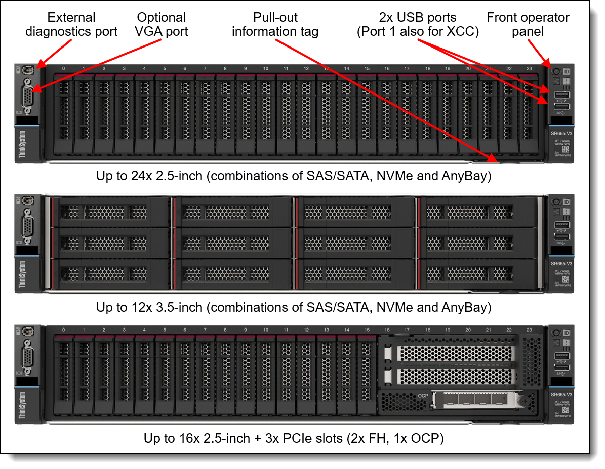
Figure 2. Front view of the ThinkSystem SR665 V3
For details on the front ports, including the optional front VGA port and front external diagnostic port, see the Local management section.
The following figure shows the components visible from the rear of the server. The figure shows one configuration, with eight full-height PCIe slots, however there are additional rear configurations which include 10 PCIe slots (6x full-height, 4x low-profile), or include 3.5-inch drive bays or 2.5-inch drive bays. The server also supports two rear-accessible 7mm hot-swap drive bays.
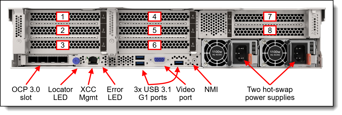
Figure 3. Rear view of the ThinkSystem SR665 V3 (configuration with eight full-height PCIe slots)
The following figure shows the locations of key components inside the server.
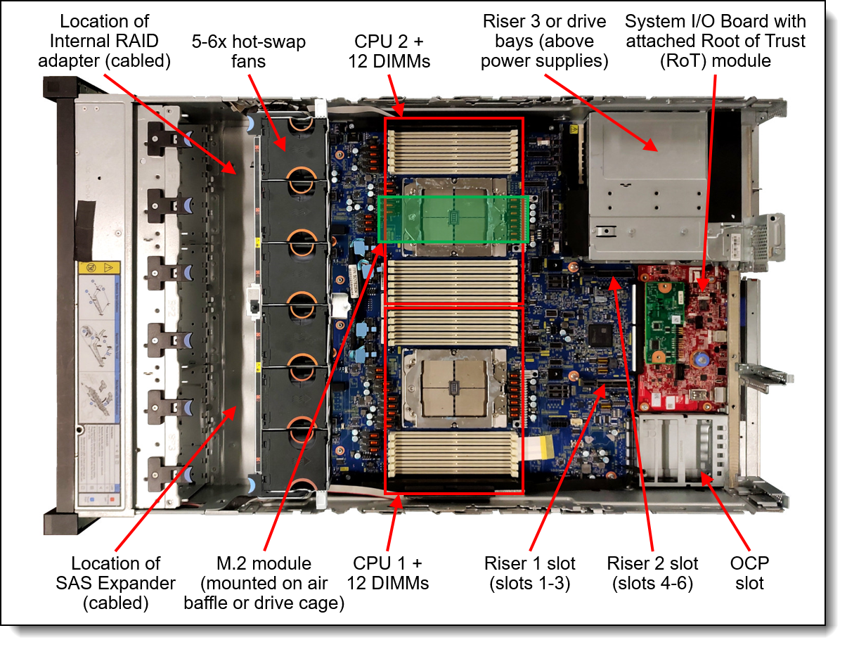
Figure 4. Internal view of the ThinkSystem SR665 V3
System architecture
The following figure shows the architectural block diagram of the SR665 V3, showing the major components and their connections.
Note that one of the xGMI links between the processors can be used instead as two PCIe 5.0 x16 connections. These PCIe connections can be used for additional NVMe drive support.
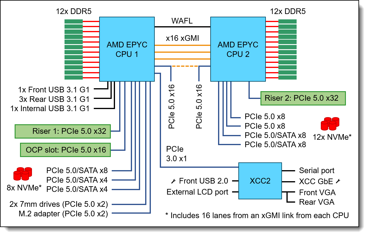
Figure 5. SR665 V3 system architectural block diagram
Standard specifications
The following table lists the standard specifications.
| Components | Specification |
|---|---|
| Machine types | 7D9B - 1 year warranty 7D9A - 3 year warranty |
| Form factor | 2U rack. |
| Processor | One or two AMD EPYC 9004 Series processors (formerly codenamed "Genoa"). Supports processors up to 128 cores, core speeds of up to 4.1 GHz, and TDP ratings of up to 360W. Supports PCIe 5.0 for high performance I/O. |
| Chipset | Not applicable (platform controller hub functions are integrated into the processor) |
| Memory | 24 DIMM slots with two processors (12 DIMM slots per processor). Each processor has 12 memory channels, with 1 DIMM per channel (DPC). Lenovo TruDDR5 RDIMMs, 3DS RDIMMs, and 9x4 RDIMMs are supported, up to 4800 MHz |
| Memory maximum | Up to 6TB with 24x 256GB 3DS RDIMMs |
| Persistent memory | Not supported. |
| Memory protection | ECC, SDDC, Patrol/Demand Scrubbing, Bounded Fault, DRAM Address Command Parity with Replay, DRAM Uncorrected ECC Error Retry, On-die ECC, ECC Error Check and Scrub (ECS), Post Package Repair |
| Disk drive bays |
Up to 20x 3.5-inch or 40x 2.5-inch hot-swap drive bays:
The server also supports these drives for OS boot or drive storage:
See Storage configurations for details. |
| Maximum internal storage |
|
| Storage controller |
|
| Optical drive bays | No internal optical drive |
| Tape drive bays | No internal backup drive |
| Network interfaces | Dedicated OCP 3.0 SFF slot with PCIe 5.0 x16 host interface, either at the rear of the server (rear-accessible) or the front of the server (front-accessible). Supports a variety of 2-port and 4-port adapters with 1GbE, 10GbE and 25GbE network connectivity. One port can optionally be shared with the XClarity Controller 2 (XCC2) management processor for Wake-on-LAN and NC-SI support. Additional PCIe network adapters supported in PCIe slots. |
| PCI Expansion slots |
Up to 12x PCIe slots (10x rear, 2x front), plus a slot dedicated to an OCP 3.0 adapter. 2.5-inch drive configurations also support an additional internal bay for a cabled RAID adapter or HBA. Rear: Up to 10x PCIe slots, plus a slot dedicated to the OCP adapter. Slot are either PCIe 5.0 or 4.0 depending on riser selection and rear drive bay selection. The use of some slots requires two processors. Slots are configured using three riser cards. Riser 1 (slots 1-3) and Riser 2 (slots 4-6) are installed in slots in the system board, Riser 3 (slots 7-8) and Riser 4 (9-10) are cabled to ports on the system board. A variety of riser cards are available. See the I/O expansion for details. Front: The server also supports slots at the front of the server (configurations with up to 16 drive bays): 2x PCIe x16 full-height half-length slots, plus 1x OCP 3.0 slot Internal: For 2.5-inch front drive configurations, the server supports the installation of a RAID adapter or HBA in a dedicated area that does not consume any of the PCIe slots. |
| Ports |
Front: 1x USB 3.2 G1 (5 Gb/s) port, 1x USB 2.0 port (also for XCC local management), External diagnostics port, optional VGA port. Rear: 3x USB 3.2 G1 (5 Gb/s) ports, 1x VGA video port, 1x RJ-45 1GbE systems management port for XCC remote management. Optional 2nd XCC remote management port (installs in OCP slot). Optional DB-9 COM serial port (installs in slot 3). Internal: 1x USB 3.2 G1 (5 Gb/s) connector for operating system or license key purposes. |
| Cooling | Up to 6x N+1 redundant hot swap 60 mm fans, configuration dependent. One fan integrated in each power supply. |
| Power supply | Up to two hot-swap redundant AC power supplies, 80 PLUS Platinum or 80 PLUS Titanium certification. 750 W, 1100 W, 1800 W, 2400 W, and 2600 W AC, supporting 220 V AC. 750 W and 1100 W options also support 110V input supply. In China only, all power supply options support 240 V DC. Also available is a 1100W power supply with a -48V DC input. |
| Video | Embedded video graphics with 16 MB memory with 2D hardware accelerator, integrated into the XClarity Controller. Maximum resolution is 1920x1200 32bpp at 60Hz. |
| Hot-swap parts | Drives, power supplies, and fans. |
| Systems management | Operator panel with status LEDs. Optional External Diagnostics Handset with LCD display. Models with 16x 2.5-inch front drive bays can optionally support an Integrated Diagnostics Panel. XClarity Controller 2 (XCC2) embedded management based on the ASPEED AST2600 baseboard management controller (BMC). Dedicated rear Ethernet port for XCC2 remote access for management. Optional 2nd redundant XCC2 remote port supported, installs in the OCP slot. XClarity Administrator for centralized infrastructure management, XClarity Integrator plugins, and XClarity Energy Manager centralized server power management. Optional XCC Platinum to enable remote control functions and other features. |
| Security features | Chassis intrusion switch, Power-on password, administrator's password, Root of Trust module supporting TPM 2.0 and Platform Firmware Resiliency (PFR). Optional lockable front security bezel. |
| Operating systems supported | Microsoft Windows Server, Microsoft Windows 10 & 11, Red Hat Enterprise Linux, SUSE Linux Enterprise Server, VMware ESXi, Ubuntu Server. See the Operating system support section for specifics. |
| Limited warranty | Three-year or one-year (model dependent) customer-replaceable unit and onsite limited warranty with 9x5 next business day (NBD). |
| Service and support | Optional service upgrades are available through Lenovo Services: 4-hour or 2-hour response time, 6-hour fix time, 1-year or 2-year warranty extension, software support for Lenovo hardware and some third-party applications. |
| Dimensions | Width: 445 mm (17.5 in.), height: 87 mm (3.4 in.), depth: 766 mm (30.1 in.). See Physical and electrical specifications for details. |
| Weight | Maximum: 38.8 kg (85.5 lb) |
Models
ThinkSystem SR665 V3 models can be configured by using the Lenovo Data Center Solution Configurator (DCSC).
Topics in this section:
CTO models
ThinkSystem SR665 V3 models can be configured by using the Lenovo Data Center Solution Configurator (DCSC).
Configure-to-order (CTO) models are used to create models with factory-integrated server customizations. For CTO models, two types of base CTO models are available for the SR665 V3 as listed in the columns in the following table:
- General purpose base CTO models are for general business (non-HPC) and is selectable by choosing General Purpose mode in DCSC.
- AI and HPC base models are intended for Artificial Intelligence (AI) and High Performance Computing (HPC) configurations and solutions are enabled using the AI & HPC Hardware - ThinkSystem Hardware mode in DCSC. These configurations, along with Lenovo EveryScale Solutions, can also be built using System x and Cluster Solutions Configurator (x-config). Tip: Some HPC and AI models are not listed in DCSC and can only be configured in x-config.
Controlled GPU models: The "Controlled GPU" base CTO models listed in the table are the only models that support high-performance GPUs and accelerators. These models are classified under US Government ECCN regulations and have limited market and customer availability. All other base models do not support high-performance GPUs.
Preconfigured server models may also be available for the SR665 V3, however these are region-specific; that is, each region may define their own server models, and not all server models are available in every region.
The following table lists the base CTO models of the ThinkSystem SR665 V3 server.
| Machine Type/Model General purpose |
Machine Type/Model for AI and HPC |
Description |
|---|---|---|
| 7D9ACTO1WW | 7D9ACTOLWW | ThinkSystem SR665 V3-3yr Warranty |
| 7D9ACTOAWW | 7D9ACTOHWW | ThinkSystem SR665 V3-3yr Warranty with Controlled GPU |
| 7D9BCTO1WW | 7D9BCTOLWW | ThinkSystem SR665 V3-1yr Warranty |
CTO models for Windows 10 and Windows 11
The SR665 V3 can run Windows 10 and Windows 11, however only a subset of adapters and drives can be installed. For ease of configuration, the following Base CTO models have been announced to assist building a configuration that can be used with the client operating systems. For more information, see the Windows 10 and Windows 11 section.
| Machine Type/Model | Description |
|---|---|
| 7D9ACTO2WW | ThinkSystem SR665 V3 Workstation - 3 year Warranty |
| 7D9BCTO2WW | ThinkSystem SR665 V3 Workstation - 1 year Warranty |
Base feature codes
Models of the SR665 V3 are defined based on whether the server has 2.5-inch drive bays at the front (called the 2.5-inch chassis) or whether it has 3.5-inch drive bays at the front (called the 3.5-inch chassis). For models, the feature codes for these chassis bases are as listed in the following table.
| Feature code | Description |
|---|---|
| BLKJ | ThinkSystem V3 2U 12x3.5" Chassis |
| BLKK | ThinkSystem V3 2U 24x2.5" Chassis |
Preconfigured models
The following tables list the available preconfigured models, grouped by region.
- Models for Asia Pacific region
- Models for Australia and New Zealand
- Models for EMEA region
- Models for India
Refer to the Specifications section for information about standard features of the server.
Common to all models:
- Power supplies are Platinum unless otherwise stated
- All models include a Toolless Slide Rail Kit
Models for Asia Pacific region
The following table lists the models for the Asia Pacific region: Australia, Bangladesh, Brunei, Hong Kong, India, Japan, Korea, Sri Lanka, Malaysia, New Zealand, Philippines, Singapore, Thailand, Taiwan, Vietnam
| Model | AMD EPYC processor† | Memory | RAID | Drive bays | OCP | Slots | Power supply |
Fans |
Front VGA
|
Front diag
|
XCC2
|
Intru switch
|
|---|---|---|---|---|---|---|---|---|---|---|---|---|
| Standard models with a 3-year warranty (machine type 7D9A) | ||||||||||||
|
7D9AA01JAP |
1x 9124 16C 200W 3.0G | 1x16GB | 9350-8i | 8x 2.5" SAS Open bay | 4x1G I350 | 3 (x16, x8, x8) Gen4 | 1x750W | 5x Perf | Opt | Opt | Std | Opt |
|
7D9AA01KAP |
1x 9124 16C 200W 3.0G | 1x16GB | 9350-8i | 12x 3.5" SAS w/Expander Open bay | 4x1G I350 | 3 (x16, x8, x8) Gen4 | 1x750W | 5x Perf | Opt | Opt | Std | Opt |
|
7D9AA01LAP |
1x 9224 24C 200W 2.5G | 1x16GB | 9350-8i | 12x 3.5" SAS w/Expander Open bay | 4x1G I350 | 3 (x16, x8, x8) Gen4 | 1x750W | 5x Perf | Opt | Opt | Std | Opt |
|
7D9AA01MAP |
1x 9224 24C 200W 2.5G | 1x16GB | 9350-8i | 8x 2.5" SAS Open bay | 4x1G I350 | 3 (x16, x8, x8) Gen4 | 1x750W | 5x Perf | Opt | Opt | Std | Opt |
† Processor description: Processor model, number of cores, thermal design power (TDP), core frequency
Models for Australia and New Zealand
AP models: Customers in Australia and New Zealand also have access to the Asia Pacific region models.
Common to all Australia and New Zealand models:
- All models include a Toolless Slide Rail Kit and Cable Management Arm
| Model | AMD EPYC processor† | Memory | RAID | Drive bays | OCP | Slots | Power supply |
Fans |
Front VGA
|
Front diag
|
XCC2
|
Intru switch
|
|---|---|---|---|---|---|---|---|---|---|---|---|---|
| TopSeller models with a 3-year warranty (machine type 7D9A) | ||||||||||||
|
7D9AA01EAU |
1x 9124 16C 200W 3.0G | 1x16GB | 5350-8i | 8x 2.5" SAS Open bay | Open | 3 (x16, x8, x8) Gen4 | 1x750W | 5x Perf | Yes | Opt | Std | Opt |
|
7D9AA01FAU |
1x 9124 16C 200W 3.0G | 1x16GB | 9350-8i | 8x 2.5" SAS Open bay | Open | 3 (x16, x8, x8) Gen4 | 1x750W | 5x Perf | Yes | Opt | Std | Opt |
|
7D9AA01GAU |
1x 9224 24C 200W 2.5G | 1x32GB 2Rx8 | 9350-8i | 8x 2.5" SAS Open bay | Open | 3 (x16, x8, x8) Gen4 | 1x750W | 5x Perf | Yes | Opt | Std | Opt |
† Processor description: Processor model, number of cores, thermal design power (TDP), core frequency
Models for EMEA region
| Model | AMD EPYC processor† | Memory | RAID | Drive bays | OCP | Slots | Power supply |
Fans |
Front VGA
|
Front diag
|
XCC2
|
Intru switch
|
|---|---|---|---|---|---|---|---|---|---|---|---|---|
| Standard models with a 3-year warranty (machine type 7D9A) | ||||||||||||
|
7D9AA010EA |
1x 9124 16C 200W 3.0G | 1x32GB 2Rx8 | 9350-8i 2GB Int | 8x 2.5" SAS Open bay | Open | 3 (x16, x8, x8) Gen4 | 1x1100W Titanium | 5x Perf | Opt | Yes | Plat | Opt |
|
7D9AA01TEA |
1x 9124 16C 200W 3.0G | 1x32GB 1Rx4 | Option | Option 2.5" Open bay | Open | Open | 1x1100W Titanium | 5x Std | Opt | Opt | Plat | Opt |
|
7D9AA025EA |
1x 9124 16C 200W 3.0G | 1x32GB 1Rx4 | Option | Option 2.5" Open bay | Open | Open | 1x1100W Titanium | 5x Std | Opt | Opt | Plat | Opt |
|
7D9AA01QEA |
1x 9174F 16C 320W 4.1G | 1x32GB 1Rx4 | Option | Option 2.5" Open bay | Open | Open | 1x1800W Titanium | 5x Perf | Opt | Opt | Plat | Opt |
|
7D9AA026EA |
1x 9174F 16C 320W 4.1G | 1x32GB 1Rx4 | Option | Option 2.5" Open bay | Open | Open | 1x1800W Titanium | 5x Perf | Opt | Opt | Plat | Opt |
|
7D9AA01PEA |
1x 9254 24C 200W 2.9G | 1x64GB | Option | Option 2.5" Open bay | Open | Open | 1x1100W Titanium | 5x Std | Opt | Opt | Plat | Opt |
|
7D9AA01ZEA |
1x 9254 24C 200W 2.9G | 1x32GB 1Rx4 | Option | Option 2.5" Open bay | Open | Open | 1x1100W Titanium | 5x Std | Opt | Opt | Plat | Opt |
|
7D9AA01REA |
1x 9274F 24C 320W 4.05G | 1x64GB | Option | Option 2.5" Open bay | Open | Open | 1x1800W Titanium | 5x Perf | Opt | Opt | Plat | Opt |
|
7D9AA01XEA |
1x 9274F 24C 320W 4.05G | 1x32GB 1Rx4 | Option | Option 2.5" Open bay | Open | Open | 1x1800W Titanium | 5x Perf | Opt | Opt | Plat | Opt |
|
7D9AA00ZEA |
1x 9334 32C 210W 2.7G | 1x32GB 2Rx8 | 9350-8i 2GB Int | 8x 2.5" SAS Open bay | Open | 3 (x16, x8, x8) Gen4 | 1x1100W Titanium | 5x Perf | Opt | Yes | Plat | Opt |
|
7D9AA00XEA |
1x 9354 32C 280W 3.25G | 1x64GB | 9350-8i 2GB Int | 8x 2.5" SAS Open bay | Open | 3 (x16, x8, x8) Gen4 | 1x1100W Titanium | 5x Perf | Opt | Yes | Plat | Opt |
|
7D9AA01HEA |
2x 9354 32C 280W 3.25G | 24x32GB 2Rx8 | Option | Option 2.5" Open bay 1x M.2 SATA/x4NVMe, 1x 960GB 7450 PRO M.2 |
4x1G 5719 | 6x x16 Gen5 | 2x 1800W | 6x Perf | Opt | Opt | Std | Opt |
|
7D9AA01SEA |
1x 9354 32C 280W 3.25G | 1x64GB | Option | Option 2.5" Open bay | Open | Open | 1x1800W Titanium | 5x Perf | Opt | Opt | Plat | Opt |
|
7D9AA01YEA |
1x 9354 32C 280W 3.25G | 1x32GB 1Rx4 | Option | Option 2.5" Open bay | Open | Open | 1x1800W Titanium | 5x Perf | Opt | Opt | Plat | Opt |
|
7D9AA00YEA |
1x 9534 64C 280W 2.45G | 1x64GB | 9350-8i 2GB Int | 8x 2.5" SAS Open bay | Open | 3 (x16, x8, x8) Gen4 | 1x1100W Titanium | 5x Perf | Opt | Yes | Plat | Opt |
|
7D9AA00WEA |
1x 9554 64C 360W 3.1G | 2x64GB | 9350-8i 2GB Int | 8x 2.5" SAS Open bay | Open | 3 (x16, x8, x8) Gen4 | 1x1800W Titanium | 5x Perf | Opt | Yes | Plat | Opt |
† Processor description: Processor model, number of cores, thermal design power (TDP), core frequency
Models for India
Common to all India models:
- All models include a Toolless Slide Rail Kit with Cable Management Arm (CMA)
AP models: Customers in India also have access to the Asia Pacific region models.
| Model | AMD EPYC processor† | Memory | RAID | Drive bays | OCP | Slots | Power supply |
Fans |
Front VGA
|
Front diag
|
XCC2
|
Intru switch
|
|---|---|---|---|---|---|---|---|---|---|---|---|---|
| TopSeller models with a 3-year warranty (machine type 7D9A) | ||||||||||||
|
7D9AA02BSG |
1x 9124 16C 200W 3.0G | 1x32GB 1Rx4 | Option | 16x 2.5" Any Open bay | 2x10GT 57416 | 3 (x16, x8, x8) Gen4 | 2x 1100W | 5x Perf | Opt | Opt | Std | Opt |
|
7D9AA02ESG |
1x 9124 16C 200W 3.0G | 1x32GB 2Rx8 | 5350-8i | 8x 3.5" SAS Open bay | 2x10GT 57416 | 2 (x16, x16) Gen4 | 2x 1100W | 5x Perf | Yes | Opt | Std | Opt |
|
7D9AA02FSG |
1x 9124 16C 200W 3.0G | 1x32GB 2Rx8 | Option | 16x 2.5" Any Open bay | 2x10GT 57416 | 2 (x16, x16) Gen4 | 2x 1100W | 5x Perf | Yes | Opt | Std | Opt |
|
7D9AA02KSG |
1x 9124 16C 200W 3.0G | 1x32GB 2Rx8 | 5350-8i | 8x 2.5" SAS Open bay | 2x10GT 57416 | 2 (x16, x16) Gen4 | 2x 1100W | 5x Perf | Yes | Opt | Std | Opt |
|
7D9AA02JSG |
1x 9254 24C 200W 2.9G | 1x32GB 2Rx8 | 5350-8i | 8x 2.5" SAS Open bay | 2x10GT 57416 | 2 (x16, x16) Gen4 | 2x 1100W | 5x Perf | Yes | Opt | Std | Opt |
|
7D9AA02HSG |
1x 9334 32C 210W 2.7G | 1x32GB 2Rx8 | 5350-8i | 8x 2.5" SAS Open bay | 2x10GT 57416 | 2 (x16, x16) Gen4 | 2x 1100W | 5x Perf | Yes | Opt | Std | Opt |
|
7D9AA02GSG |
1x 9534 64C 280W 2.45G | 1x32GB 2Rx8 | 5350-8i | 8x 2.5" SAS Open bay | 2x10GT 57416 | 2 (x16, x16) Gen4 | 2x 1100W | 5x Perf | Yes | Opt | Std | Opt |
† Processor description: Processor model, number of cores, thermal design power (TDP), core frequency
Processors
The SR665 V3 supports processors in the fourth-generation AMD EPYC family of processors. The server supports one or two processors.
Topics in this section:
Processor options
The table below lists the AMD processors that are currently supported by the SR665 V3.
All supported processors have the following characteristics:
- Fourth-generation AMD EPYC processors (formerly codenamed "Genoa")
- 12 DDR5 memory channels
- 128 PCIe 5.0 I/O lanes, 64 lanes available for PCIe and NVMe devices
The SR665 V3 also supports the new 4th Gen AMD EPYC processors with "Zen 4c" architecture (formerly codenamed "Bergamo"). These processors have higher core counts, up to 128 cores, targeted at cloud native applications that are designed to exploit the scale, elasticity, resiliency, and flexibility of private & public clouds.
| Part number* |
Feature code |
SKU | Description | Quantity supported* |
|---|---|---|---|---|
| 4th Gen AMD EPYC processors ("Genoa") | ||||
| 4XG7A85822 | BREE | 9124 | ThinkSystem SR665 V3 AMD EPYC 9124 16C 200W 3.0GHz Processor w/o Fan | 1 or 2 |
| 4XG7A85827 | BREJ | 9174F | ThinkSystem SR665 V3 AMD EPYC 9174F 16C 320W 4.1GHz Processor w/o Fan | 1 or 2 |
| 4XG7A85819 | BREH | 9224 | ThinkSystem SR665 V3 AMD EPYC 9224 24C 200W 2.5GHz Processor w/o Fan | 1 or 2 |
| 4XG7A85821 | BRED | 9254 | ThinkSystem SR665 V3 AMD EPYC 9254 24C 200W 2.9GHz Processor w/o Fan | 1 or 2 |
| 4XG7A85826 | BREF | 9274F | ThinkSystem SR665 V3 AMD EPYC 9274F 24C 320W 4.05GHz Processor w/o Fan | 1 or 2 |
| 4XG7A85820 | BREC | 9334 | ThinkSystem SR665 V3 AMD EPYC 9334 32C 210W 2.7GHz Processor w/o Fan | 1 or 2 |
| 4XG7A85824 | BR30 | 9354 | ThinkSystem SR665 V3 AMD EPYC 9354 32C 280W 3.25GHz Processor w/o Fan | 1 or 2 |
| None | BREG | 9354P | ThinkSystem AMD EPYC 9354P 32C 280W 3.25GHz Processor | 1 |
| 4XG7A85825 | BR32 | 9374F | ThinkSystem SR665 V3 AMD EPYC 9374F 32C 320W 3.85GHz Processor w/o Fan | 1 or 2 |
| 4XG7A85818 | BREB | 9454 | ThinkSystem SR665 V3 AMD EPYC 9454 48C 290W 2.75GHz Processor w/o Fan | 1 or 2 |
| None | BREM | 9454P | ThinkSystem AMD EPYC 9454P 48C 290W 2.75GHz Processor | 1 |
| 4XG7A85823 | BR31 | 9474F | ThinkSystem SR665 V3 AMD EPYC 9474F 48C 360W 3.6GHz Processor w/o Fan | 1 or 2 |
| 4XG7A85817 | BREA | 9534 | ThinkSystem SR665 V3 AMD EPYC 9534 64C 280W 2.45GHz Processor w/o Fan | 1 or 2 |
| 4XG7A85816 | BPVJ | 9554 | ThinkSystem SR665 V3 AMD EPYC 9554 64C 360W 3.1GHz Processor w/o Fan | 1 or 2 |
| None | BREL | 9554P | ThinkSystem AMD EPYC 9554P 64C 360W 3.1GHz Processor | 1 |
| 4XG7A85828 | BR2Z | 9634 | ThinkSystem SR665 V3 AMD EPYC 9634 84C 290W 2.25GHz Processor w/o Fan | 1 or 2 |
| 4XG7A85815 | BPVK | 9654 | ThinkSystem SR665 V3 AMD EPYC 9654 96C 360W 2.4GHz Processor w/o Fan | 1 or 2 |
| None | BREK | 9654P | ThinkSystem AMD EPYC 9654P 96C 360W 2.4GHz Processor | 1 |
| 4th AMD EPYC processors with AMD 3D V-Cache ("Genoa-X") | ||||
| 4XG7A91035 | BW9U | 9684X | ThinkSystem SR665 V3 AMD EPYC 9684X 96C 400W 2.55GHz Processor w/o Fan | 1 or 2 |
| 4th Gen AMD EPYC processors with Zen 4c architecture ("Bergamo") | ||||
| CTO only | BW9S | 9734 | ThinkSystem AMD EPYC 9734 112C 340W 2.2GHz Processor | 1 or 2 |
| CTO only | BW9T | 9754 | ThinkSystem AMD EPYC 9754 128C 360W 2.25GHz Processor | 1 or 2 |
* Processors with a P suffix are single-socket capable processors and are only available in configure-to-order builds or in preconfigured models. Not available as option part numbers.
Configuration notes:
- Processor options include a heatsink but do not include a system fan
| EPYC model** |
Cores / Threads |
Base Frequency |
Max Boost Frequency† |
L3 Cache | Memory channels |
Memory bus |
TDP |
|---|---|---|---|---|---|---|---|
| 4th Gen AMD EPYC processors ("Genoa") | |||||||
| 9124 | 16 / 32 | 3.0 GHz | 3.7 GHz | 64 MB | 12 | 4800 MHz | 200W |
| 9174F | 16 / 32 | 4.1 GHz | 4.4 GHz | 256 MB | 12 | 4800 MHz | 320W |
| 9224 | 24 / 48 | 2.5 GHz | 3.7 GHz | 64 MB | 12 | 4800 MHz | 200W |
| 9254 | 24 / 48 | 2.9 GHz | 4.15 GHz | 128 MB | 12 | 4800 MHz | 200W |
| 9274F | 24 / 48 | 4.05 GHz | 4.3 GHz | 256 MB | 12 | 4800 MHz | 320W |
| 9334 | 32 / 64 | 2.7 GHz | 3.9 GHz | 128 MB | 12 | 4800 MHz | 210W |
| 9354 | 32 / 64 | 3.25 GHz | 3.8 GHz | 256 MB | 12 | 4800 MHz | 280W |
| 9354P | 32 / 64 | 3.25 GHz | 3.8 GHz | 256 MB | 12 | 4800 MHz | 280W |
| 9374F | 32 / 64 | 3.85 GHz | 4.3 GHz | 256 MB | 12 | 4800 MHz | 320W |
| 9454 | 48 / 96 | 2.75 GHz | 3.8 GHz | 256 MB | 12 | 4800 MHz | 290W |
| 9454P | 48 / 96 | 2.75 GHz | 3.8 GHz | 256 MB | 12 | 4800 MHz | 290W |
| 9474F | 48 / 96 | 3.6 GHz | 4.1 GHz | 256 MB | 12 | 4800 MHz | 360W |
| 9534 | 64 / 128 | 2.45 GHz | 3.7 GHz | 256 MB | 12 | 4800 MHz | 280W |
| 9554 | 64 / 128 | 3.1 GHz | 3.75 GHz | 256 MB | 12 | 4800 MHz | 360W |
| 9554P | 64 / 128 | 3.1 GHz | 3.75 GHz | 256 MB | 12 | 4800 MHz | 360W |
| 9634 | 84 / 168 | 2.25 GHz | 3.7 GHz | 384 MB | 12 | 4800 MHz | 290W |
| 9654 | 96 / 192 | 2.4 GHz | 3.7 GHz | 384 MB | 12 | 4800 MHz | 360W |
| 9654P | 96 / 192 | 2.4 GHz | 3.7 GHz | 384 MB | 12 | 4800 MHz | 360W |
| 4th AMD EPYC processors with AMD 3D V-Cache ("Genoa-X") | |||||||
| 9684X | 96 / 192 | 2.55 GHz | 3.7 GHz | 1150 MB | 12 | 4800 MHz | 400W |
| 4th Gen AMD EPYC processors with Zen 4c architecture ("Bergamo") | |||||||
| 9734 | 112 / 224 | 2.2 GHz | 3.0 GHz | 256 MB | 12 | 4800 MHz | 340W |
| 9754 | 128 / 256 | 2.25 GHz | 3.2 GHz | 256 MB | 12 | 4800 MHz | 360W |
† The maximum single-core frequency that the processor is capable of operating
** Processors with a P suffix are single-socket capable processors
xGMI cabled connection
As shown in the System architecture section, the server has four xGMI links between the two processors. By default, three xGMI links are used for inter-processor communications, and the fourth xGMI connection is used to provide two PCIe x16 connections for additional PCIe and NVMe devices. However, to maximize CPU-to-CPU performance, the two xGMI connectors can be joined using a cable.
Ordering information for this xGMI cable is listed in the following table.
| Part number | Feature code | Description |
|---|---|---|
| 4X97A87125 | BR65 | SR665 V3 CPU interconnection Cable Kit* |
* In DCSC, this cable may be labeled "Cable126"
Configuration notes:
- The following configurations do not support the use of this xGMI cable:
- Configurations with 16 or more onboard connections to NVMe drives
- Configurations with front PCIe slots + front OCP slot + front onboard NVMe
- Configurations with 12 PCIe slots (10x rear, 2x front)
One-processor configurations
The SR665 V3 can be used with only one processor installed. Most core functions of the server (including the XClarity Controller) are connected to processor 1 as shown in the System architecture section.
With only one processor, the server has the following capabilities:
- 12 memory DIMMs
- Slot 1-3 are available; Slot 4-8 are not available
- 16 onboard SATA connections
- 8 onboard NVMe connections
Drive support and controller support is as listed in the Storage configurations section - see the rows for 1 processor installed in the tables.
Thermal requirements by processor
For thermal requirements for processors, see the Thermal Rules section in the Information Center for the SR665 V3:
https://pubs.lenovo.com/sr665-v3/thermal_rules
Additional ambient temperature restrictions may apply. See the Operating environment section for details.
Lenovo Neptune Processor DWC Module - Open-loop liquid cooling
The SR665 V3 also supports advanced direct-water cooling (DWC) capability with the Lenovo Neptune Processor DWC Module. This module implements a liquid cooling solution where heat from the processors is removed from the rack and the data center using an open loop and coolant distrubution units. The liquid used in the loop is a mixture of water and ethylene glycol (EGW).
With the Neptune Processor DWC Module, all heat generated by the processors is removed from the server using water. This means that the server fans and data center air conditioning units only need to remove the heat generated by the other components. This results in lower air conditioning costs and it enables the use of slower fans which results in lower overall power consumption.
The following figure shows the Lenovo Neptune Processor DWC Module.
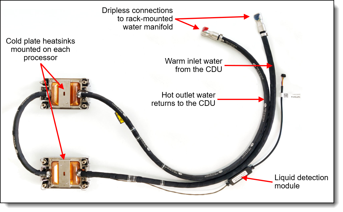
Figure 6. Lenovo Neptune Processor DWC Module
The Neptune Processor DWC Module also includes a leak detection module which can detect a leakage of more than 0.5ml (about 10 drops) along the length of the tube and then issue an event to the XClarity Controller. XCC will then post an error to the System Event Log and enable further actions. Once the liquid evaporates, a further event is issue to XCC.
The Neptune Processor DWC Module is only available in CTO orders, not as a field upgrade. Ordering information is listed in the following table.
| Part number | Feature code | Description |
|---|---|---|
| CTO only | BZGM* | ThinkSystem V3 Neptune Processor Direct Water Cooling Solution |
* In DCSC, this feature code is listed in the Processor tab
Configuration notes:
- The Neptune Processor DWC Module requires water infrastructure be available in the rack cabinet and data center, as described in the Water infrastructure section.
- All processor SKUs are supported, including 400W processors
- Two CPUs are required; Configurations with one processor are not supported
- All front drive bay configurations are supported
- Slot 6 is not available for adapters - the water loop is routed through the space otherwise occupied by slot 6
- Rear drive bays are supported
- 7mm drive bays are supported only in slot 3
- M.2 adapters are supported based on the configurations in the Storage configurations section
- Standard fans can be configured in most configurations
- The use of a cable management arm (CMA) is not supported
For more information, see the Thermal Rules page:
https://pubs.lenovo.com/sr665-v3/thermal_rules
The following figure shows the Lenovo Neptune Processor DWC Module installed in the SR665 V3 (risers removed to show internal components).
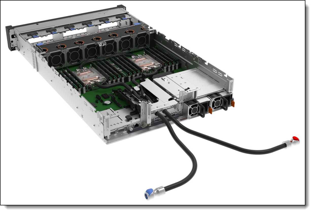
Figure 7. Lenovo Neptune Processor DWC Module installed in the SR665 V3
UEFI operating modes
The SR665 V3 offers preset operating modes that affect energy consumption and performance. These modes are a collection of predefined low-level UEFI settings that simplify the task of tuning the server to suit your business and workload requirements.
The following table lists the feature codes that allow you to specify the mode you wish to preset in the factory for CTO orders.
| Feature code | Description |
|---|---|
| BFYA | Operating mode selection for: "Maximum Efficiency Mode" |
| BFYB | Operating mode selection for: "Maximum Performance Mode" |
The preset modes for the SR665 V3 are as follows:
- Maximum Efficiency Mode (feature BFYA): Maximizes performance/watt efficiency while maintaining reasonable performance
- Maximum Performance Mode (feature BFYB): Achieves maximum performance but with higher power consumption and lower energy efficiency.
For details about these preset modes, and all other performance and power efficiency UEFI settings offered in the SR665 V3, see the paper "Tuning UEFI Settings for Performance and Energy Efficiency on AMD Processor-Based ThinkSystem Servers", available from https://lenovopress.lenovo.com/lp1267.
Platform Secure Boot
Platform Secure Boot (PSB) is a feature of AMD EPYC processors that helps defend against threats to firmware. It is designed to provide protection in response to growing firmware-level remote attacks being seen across the industry. AMD Secure Boot extends the AMD silicon root of trust to help protect the system by establishing an unbroken chain of trust from the AMD silicon root of trust to the BIOS. The UEFI secure boot helps continue the chain of trust from the system BIOS to the OS Bootloader. This feature helps defend against remote attackers seeking to embed malware into firmware.
With PSB enabled, the processor is cryptographically bound to the server firmware code signing key once the processors are installed in the server and the server is powered on. From that point on, that processor can only be used with motherboards that use the same code signing key.
Disabling PSB will stop the protection against remote and local attackers seeking to embed malware into a platform’s firmware, BIOS and even UEFI functions. Disabling PSB also allows you to install the processor in another server that you purchased from Lenovo, however, we do not recommend you do this by yourself. Please contact the Lenovo service team for further assistance.
By default, the server has Platform Secure Boot enabled on the installed processors, however for factory orders, you can choose to have the server with PSB disabled. To do this, select the feature code listed in the following table. PSB can be later enabled in System Setup if desired.
Cannot be disabled once enabled: Once you enable PSB in a server, it cannot be disabled on those processors.
| Feature code | Description | Purpose |
|---|---|---|
| C18D | Platform Secure Boot Disable | PSB is not enabled in the factory. It can be later enabled in UEFI System Setup if desired. |
If you add a second processor as a field upgrade and your server has PSB enabled, then as soon as you install the processor and power the server on, the processor is then cryptographically bound to the server, and can only be used in that server going forward.
Note: Platform Secure Boot (PSB) is different from the Secure Boot security feature described in the Platform Firmware Resiliency section.
Memory options
The SR665 V3 uses Lenovo TruDDR5 memory operating at up to 4800 MHz. The server supports up to 24 DIMMs with 2 processors. The processors have 12 memory channels and support 1 DIMM per channel. The server supports up to 6TB of memory using 24x 256GB 3DS RDIMMs and two processors.
The following table lists the memory options that are available for the server.
Lenovo TruDDR5 memory uses the highest quality components that are sourced from Tier 1 DRAM suppliers and only memory that meets the strict requirements of Lenovo is selected. It is compatibility tested and tuned to maximize performance and reliability. From a service and support standpoint, Lenovo TruDDR5 memory automatically assumes the system warranty, and Lenovo provides service and support worldwide.
| Part number | Feature code | Description |
|---|---|---|
| 9x4 RDIMMs | ||
| 4X77A81439 | BQ3E | ThinkSystem 32GB TruDDR5 4800MHz (1Rx4) 9x4 RDIMM-A |
| 4X77A81442 | BQ36 | ThinkSystem 64GB TruDDR5 4800MHz (2Rx4) 9x4 RDIMM-A |
| 10x4 RDIMMs | ||
| 4X77A81438 | BQ39 | ThinkSystem 32GB TruDDR5 4800MHz (1Rx4) 10x4 RDIMM-A |
| 4X77A81441 | BQ3D | ThinkSystem 64GB TruDDR5 4800MHz (2Rx4) 10x4 RDIMM-A |
| 4X77A81448 | BUVV | ThinkSystem 96GB TruDDR5 4800MHz (2Rx4) 10x4 RDIMM-A |
| x8 RDIMMs | ||
| 4X77A81437 | BQ3C | ThinkSystem 16GB TruDDR5 4800MHz (1Rx8) RDIMM-A |
| 4X77A81440 | BQ37 | ThinkSystem 32GB TruDDR5 4800MHz (2Rx8) RDIMM-A |
| 10x4 3DS RDIMMs | ||
| 4X77A81443 | BQ3A | ThinkSystem 128GB TruDDR5 4800MHz (4Rx4) 3DS RDIMM-A v2 |
| CTO only | BYEE | ThinkSystem 128GB TruDDR5 4800MHz (4Rx4) 3DS RDIMM-A v1 |
| 4X77A81444 | BQ3B | ThinkSystem 256GB TruDDR5 4800MHz (8Rx4) 3DS RDIMM-A v2 |
| CTO only | BZPN | ThinkSystem 256GB TruDDR5 4800MHz (8Rx4) 3DS RDIMM-A v1 |
9x4 RDIMMs (also known as Optimized or EC4 RDIMMs) are a new lower-cost DDR5 memory option supported in ThinkSystem V3 servers. 9x4 DIMMs offer the same performance as standard RDIMMs (known as 10x4 or EC8 modules), however they support lower fault-tolerance characteristics. Standard RDIMMs and 3DS RDIMMs support two 40-bit subchannels (that is, a total of 80 bits), whereas 9x4 RDIMMs support two 36-bit subchannels (a total of 72 bits). The extra bits in the subchannels allow standard RDIMMs and 3DS RDIMMs to support Single Device Data Correction (SDDC), however 9x4 RDIMMs do not support SDDC. Note, however, that all DDR5 DIMMs, including 9x4 RDIMMs, support Bounded Fault correction, which enables the server to correct most common types of DRAM failures.
For more information on DDR5 memory, see the Lenovo Press paper, Introduction to DDR5 Memory, available from https://lenovopress.com/lp1618.
The following rules apply when selecting the memory configuration:
- The SR665 V3 supports quantities 1, 2, 4, 6, 8, 10, 12 DIMMs per processor; other quantities not supported
- The server supports four types of DIMMs: 9x4 RDIMMs, 10x4 RDIMMs, x8 RDIMMs and 3DS RDIMMs; UDIMMs and LRDIMMs are not supported
- Mixing of DIMM types is not supported (for example, 9x4 DIMMs with 10x4 RDIMMs)
- Mixing of 128GB 3DS RDIMMs and 256GB 3DS RDIMMs is not supported
- Mixing of 128GB 3DS RDIMMs (features BYEE and BQ3A) is not supported
- Mixing of 256GB 3DS RDIMMs (features BZPN and BQ3B) is not supported
- Mixing x4 and x8 DIMMs is not supported
- Mixing of DIMM rank counts is supported. Follow the required installation order installing the DIMMs with the higher rank counts first.
- Mixing of DIMM capacities is supported, however only two different capacities are supported across all channels of the processor (eg 16GB and 32GB). Follow the required installation order installing the larger DIMMs first.
- The use of the 128GB 3D RDIMM feature BYEE has the following requirements for thermal reasons:
- If CPU TDP > 240W, the combination of GPUs and 24x 2.5-inch drive bays is not supported
- Additional ambient temperature requirements - see https://pubs.lenovo.com/sr665-v3/thermal_rules for information
Note: Memory mirroring and memory rank sparing are not supported.
For best performance, consider the following:
- Ensure the memory installed is at least the same speed as the memory bus of the selected processor.
- Populate all 12 memory channels with identical DIMMs (same Lenovo part number)
The following memory protection technologies are supported:
- ECC detection/correction
- Bounded Fault detection/correction
- SDDC (for x4-based memory DIMMs; look for "x4" in the DIMM description. Not supported with 9x4 RDIMMs)
- Patrol/Demand Scrubbing
- DRAM Address Command Parity with Replay
- DRAM Uncorrected ECC Error Retry
- On-die ECC
- ECC Error Check and Scrub (ECS)
- Post Package Repair
Internal storage
The SR665 V3 has three drive bay zones and supports up to 20x 3.5-inch or 40x 2.5-inch hot-swap drive bays or a combination of drive bays, depending on the selected chassis and backplane configuration. The server also supports configurations without any drive bays if desired.
The three drive bay zones are as follows:
- Front:
- Up to 12x 3.5-inch hot-swap bays, or
- Up to 24x 2.5-inch hot-swap bays
- Middle:
- 4x 3.5-inch hot-swap bays, or
- 8x 2.5-inch hot-swap bays
- Rear:
- Up to 4x 3.5-inch hot-swap bays, or
- Up to 8x 2.5-inch hot-swap bays
- Also supports 2x 7mm hot-swap drives bays
All drives are hot-swap and are accessible from the front, from the rear, or from drive bays that are located in the middle of the server (accessible when you remove the top cover of the server).
The server also supports one or two M.2 drives, installed in an M.2 adapter internal to the server.
In this section:
NVMe drive support
The SR665 V3 supports NVMe drives to maximize storage performance.
- Up to 32 NVMe drives in a 2.5-inch drive configuration, without oversubscription (that is, each x4 drive has a dedicated x4 (4 lanes) connection to the processor, either direct to the processor or via a retimer adapter)
- Up to 24 installed in front bays
- Up to 32 installed in front and mid bays
- Up to 8 NVMe drives in a 3.5-inch drive configuration, without oversubscription
- All installed in mid bays
Riser 3 support: The use of the onboard NVMe ports is mutually exclusive with Riser 3, as these use the same PCIe connectors. See the System architecture section.
The specifics of these configurations are covered in the Storage configurations section. The tables in those sections indicate the number of NVMe drives in each configuration.
In addition, the SR665 V3 supports two 7mm NVMe drives for use as boot drives. These two drives optionally support RAID via a separate RAID adapter installed in a PCIe slot.
The RAID 940-8i and RAID 940-16i adapters also support NVMe through a feature named Tri-Mode support (or Trimode support). This feature enables the use of NVMe U.3 drives at the same time as SAS and SATA drives. Tri-Mode requires an AnyBay backplane. Cabling of the controller to the backplanes is the same as with SAS/SATA drives, and the NVMe drives are connected via a PCIe x1 link to the controller.
NVMe drives connected using Tri-Mode support provide better performance than SAS or SATA drives: A SATA SSD has a data rate of 6Gbps, a SAS SSD has a data rate of 12Gbps, whereas an NVMe U.3 Gen 4 SSD with a PCIe x1 link will have a data rate of 16Gbps. NVMe drives typically also have lower latency and higher IOPS compared to SAS and SATA drives. Tri-Mode is supported with U.3 NVMe drives in either 2.5-inch and 3.5-inch form factor and requires an AnyBay backplane.
Tri-Mode requires U.3 drives: Only NVMe drives with a U.3 interface are supported. U.2 drives are not supported. See the Internal drive options section for the U.3 drives supported by the server.
Front drive bays
The front drive bay zone supports the following configurations:
- 8x or 12x 3.5-inch drive bays (all hot-swap)
- 8x, 16x or 24x 2.5-inch drive bays (all hot-swap)
- No backplanes and no drives (supports field upgrades)
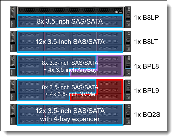
Figure 8. SR665 V3 front drive bay configurations - 3.5-inch drive bays
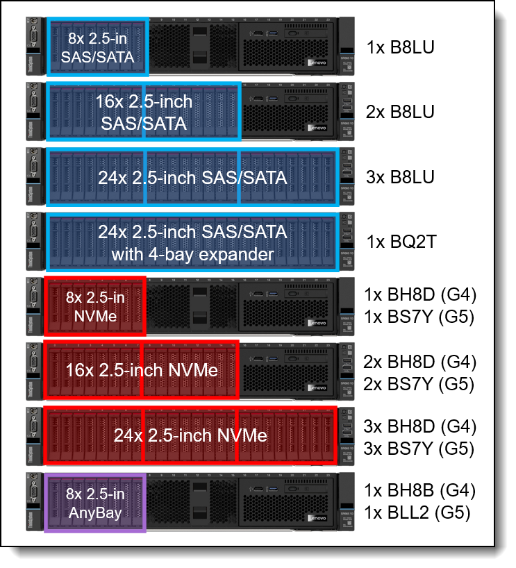
Figure 9. SR665 V3 front drive bay configurations - 2.5-inch drive bays, all the same drive type
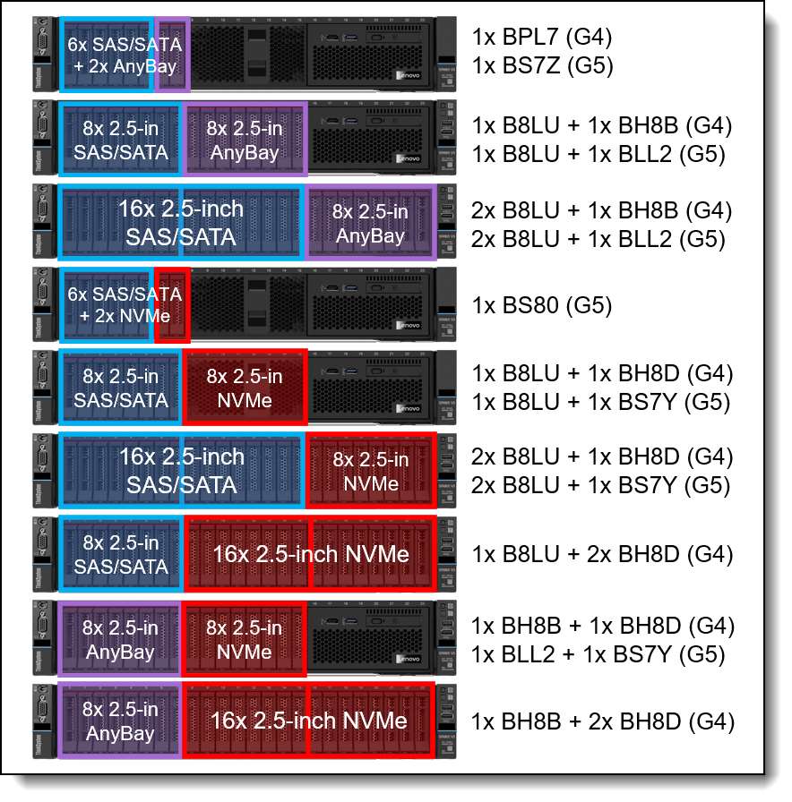
Figure 10. SR665 V3 front drive bay configurations - 2.5-inch drive bays, combinations
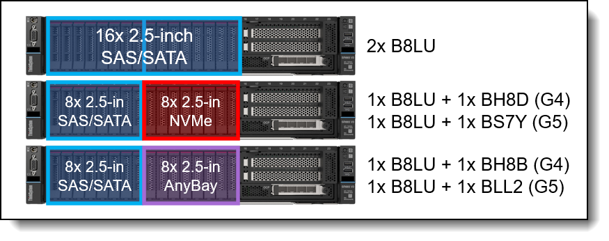
Figure 11. SR665 V3 front drive bay configurations - 2.5-inch drive bays with front PCIe slots
The backplanes used to provide these drive bays are listed in the following table.
Field upgrades: All front backplanes are available as part numbers for field upgrades along with require cable option kits, as described in the Field upgrades section below.
| Feature | Description | Bays | PCIe Gen |
Maximum supported |
|---|---|---|---|---|
| Front 3.5-inch drive backplanes | ||||
| B8LP | ThinkSystem 2U 8x3.5" SAS/SATA Backplane | 8 | - | 1 |
| B8LT | ThinkSystem 2U 12x3.5" SAS/SATA Backplane | 12 | - | 1 |
| BPL8 | ThinkSystem 2U 8x3.5" SAS/SATA+4 AnyBay Backplane | 12 | Gen4 | 1 |
| BPL9 | ThinkSystem 2U 8x3.5" SAS/SATA+4 NVMe Backplane | 12 | Gen4 | 1 |
| BQ2S | ThinkSystem 2U 12x3.5" SAS/SATA with Rear 4-Bay Expander Backplane | 12* | - | 1 |
| Front 2.5-inch drive backplanes | ||||
| B8LU | ThinkSystem 2U 8x2.5" SAS/SATA Backplane | 8 | - | 3 |
| BH8D | ThinkSystem 2U/4U 8x2.5" NVMe Backplane | 8 | Gen4 | 3 |
| BS7Y | ThinkSystem V3 2U 8x2.5" NVMe Gen5 Backplane | 8 | Gen5 | 3 |
| BH8B | ThinkSystem 2U/4U 8x2.5" AnyBay Backplane | 8 | Gen4 | 3 |
| BLL2 | ThinkSystem V3 2U 8x2.5" AnyBay Gen5 Backplane | 8 | Gen5 | 3 |
| BPL7 | ThinkSystem 2U 6x2.5" SAS/SATA+2 AnyBay Backplane | 8 | Gen4 | 1 |
| BQ2T | ThinkSystem 2U 24x2.5" SAS/SATA with Rear 4-Bay Expander Backplane | 24* | - | 1 |
| Integrated Diagnostics Panel (for 2.5-inch configurations with 8 or 16 bays only) | ||||
| BMJA | ThinkSystem 2U 16x2.5" Front Operator Panel v2 | - | - | 1 |
* Backplane has an onboard SAS expander that provides connectivity to SAS/SATA drive bays in a separate rear backplane (order the rear backplane separately). See also note below for BQ2T.
The use of front drive bays has the following configuration rules:
- The SR665 V3 also supports configurations without any drive bays, allowing for drive bay upgrades as described in the field upgrades section.
- If 3.5-inch front drive bays are used, an internal (CFF) RAID adapter or HBA is not supported as the adapter and bays occupy the same physical space
- Any 8x 2.5-inch and 16x 2.5-inch drive configuration (SAS/SATA, AnyBay, or NVMe) can optionally be configured for use with the Integrated Diagnostics Panel as described in the Local management section. 3.5-inch drive configurations do not support the Integrated Diagnostics Panel. With the Integrated Diagnostics Display, 8-bay configurations can be upgrade to 16 bays, however 16-bay configurations cannot be upgrade to 24 bays.
- If you are building a server configuration that includes the ThinkSystem 2U 24x2.5" SAS/SATA with Rear 4-Bay Expander Backplane (feature BQ2T) and the order also includes a rack cabinet, then you can configure at most 6 drives to be installed in the factory. The remaining drives must be ordered separately using the option part numbers for the drives. This requirement does not apply if the order does not include a rack cabinet. The requirement is due to the shock/vibration limits of the 24x 2.5-inch backplane.
Mid drive bays
The SR665 V3 supports hot-swap drives installed in the middle of the server chassis. The drive bays are accessible by removing the top lid of the server and levering the mid drive chassis up at the front.
The following configurations are supported:
- 4x 3.5-inch hot-swap SAS/SATA drive bays
- 8x 2.5-inch hot-swap SAS/SATA drive bays
- 8x 2.5-inch hot-swap NVMe drive bays
The drive bays in the open position are shown in the following figure.
M.2 support: When mid drive bays are configured, the M.2 adapter is installed on the mid drive bay mechanical as shown in the images.
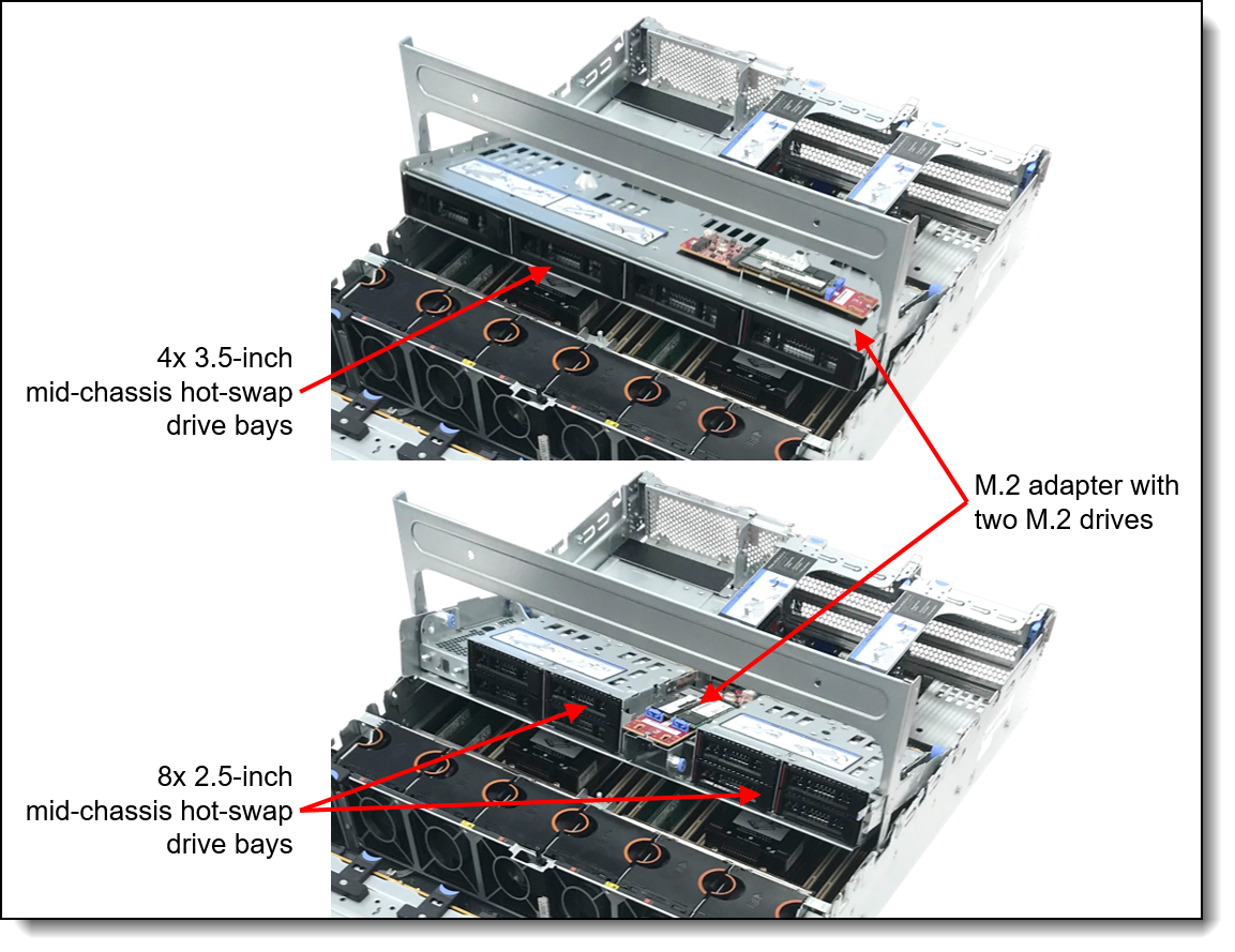
Figure 12. Mid-chassis drive bays
The backplanes used to provide these drive bays are listed in the following table.
| Feature code |
Description | PCIe Gen |
Maximum supported |
|---|---|---|---|
| Mid - 3.5-inch drive backplane | |||
| BCQK | ThinkSystem 2U 4x3.5" SAS/SATA Middle Backplane | - | 1 |
| Mid - 2.5-inch drive backplane | |||
| BCQL | ThinkSystem 2U 4x2.5" SAS/SATA Middle Backplane | - | 2‡ |
| BDY7 | ThinkSystem 2U 4x2.5" Middle NVMe Backplane | Gen4 | 2‡ |
‡ 2.5-inch drive backplanes for the mid-chassis area must be installed in pairs. NVMe and SAS/SATA cannot be mixed.
Field upgrades: Backplanes are available as part numbers for field upgrades along with require cable option kits, as described in the Field upgrades section below.
The use of drive bays in the mid-chassis area has the following configuration rules:
- All processors are supported. Higher TDP processors will require the performance heatsinks.
- Full-length adapter cards are not supported
- GPUs (including low profile GPUs such as the NVIDIA A2) are not supported
- The use of mid drive bays requires Riser 1 be installed, since power for the mid bay backplanes comes from Riser 1
Rear drive bays
The SR665 V3 supports hot-swap drives installed at the rear of the server chassis. Supported configurations are as follows:
- 3.5-inch hot-swap drives
- 2x SAS/SATA drive bays
- 4x SAS/SATA drive bays
- 2.5-inch hot-swap drives
- 4x SAS/SATA drive bays
- 4x AnyBay drive bays
- 8x SAS/SATA drive bays
The configurations are shown in the following figure.
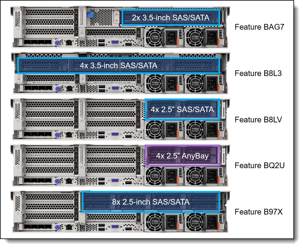
Figure 13. Rear 2.5-inch and 3.5-inch drive bay configurations
The backplanes used to provide these drive bays are listed in the following table.
7mm drives: The SR665 V3 supports two 7mm drives. See the 7mm drives section for details.
| Feature code |
Description | PCIe Gen |
Maximum supported |
|---|---|---|---|
| Rear - 3.5-inch drive backplanes | |||
| BAG7 | ThinkSystem 2U 2x3.5" SAS/SATA Rear Backplane | - | 1 |
| B8L3 | ThinkSystem 1U/2U 4x3.5" SAS/SATA Backplane | - | 1 |
| Rear - 2.5-inch drive backplanes | |||
| B8LV | ThinkSystem 2U 4x2.5" SAS/SATA Backplane | - | 1 |
| BQ2U | ThinkSystem V3 1U/2U 4x2.5" AnyBay Backplane | Gen4 | 1 |
| B97X | ThinkSystem 2U 8x2.5" SAS/SATA Rear Backplane | 1 | 1 |
Field upgrades: Backplanes are available as part numbers for field upgrades along with require cable option kits, as described in the Field upgrades section below.
The use of rear drive bays has the following configuration rules:
- The use of rear bays restricts the number of slots and the choice of risers that are supported. See the I/O expansion section for details.
- The use of rear drive bays may require that Riser 1 or Riser 2 be installed, since power for the rear backplane comes from that riser.
Storage configurations
This section describes the various combinations of front and rear drives that the server supports, as well as M.2 support.
Tip: These tables are based on Config Matrix V1.5H in TRD 4.1.
In this section:
- Overview of configurations - 3.5-inch front drive bays
- Overview of configurations - 2.5-inch front drives supporting rear slots (no front slots)
- Overview of configurations - 2.5-inch front drives supporting front slots (no rear slots)
- Overview of configurations - 2.5-inch front drives supporting 12 slots (front & rear)
- Details - 3.5-inch front drive bays
- Details - 2.5-inch front drives supporting rear slots (no front slots)
- Details - 2.5-inch front drives supporting front slots (no rear slots)
- Details - 2.5-inch front drives supporting 12 slots (front & rear)
The following tables summarize the storage configurations for the SR665 V3. For details, including processor requirements, M.2 and 7mm support, and controller selections, see each of the Details tables.
Overview - 3.5-inch front drives
The following table summarizes the configurations that use 3.5-inch front drive bays.
Click to jump down to the details of the 3.5-inch front drive configurations.
Return to Storage configurations.
| Config | Total drives (NVMe) |
Front | Mid | Rear | Backplanes | ||||||
|---|---|---|---|---|---|---|---|---|---|---|---|
| SAS/ SATA |
Any Bay |
NVMe | 3.5" SAS |
2.5" SAS |
2.5" NVMe |
3.5" SAS |
2.5" SAS |
2.5" Any |
|||
| 1 | 8 (0) | 8 | 0 | 0 | 0 | 0 | 0 | 0 | 0 | 0 | 8x3.5" SAS/SATA (B8LP) |
| 2 | 12 (0) | 12 | 0 | 0 | 0 | 0 | 0 | 0 | 0 | 0 | 12x3.5" SAS/SATA (B8LT) |
| 2A | 12 (0) | 12 | 0 | 0 | 0 | 0 | 0 | 0 | 0 | 0 | 12x3.5" SAS/SATA with Expander (BQ2S) |
| 3 | 12 (4) | 8 | 4 | 0 | 0 | 0 | 0 | 0 | 0 | 0 | 8xSAS/SATA+ 4xAnyBay G4 (BPL8) |
| 3A | 12 (4) | 8 | 0 | 4 | 0 | 0 | 0 | 0 | 0 | 0 | 8xSAS/SATA+ 4xNVMe G4 (BPL9) |
| 4 | 14 (0) | 12 | 0 | 0 | 0 | 0 | 0 | 2 | 0 | 0 | Front: 12x3.5" SAS/SATA (B8LT); Rear: 2x3.5" SAS/SATA (BAG7) |
| 4A | 14 (0) | 12 | 0 | 0 | 0 | 0 | 0 | 2 | 0 | 0 | Front: 12x3.5" SAS/SATA with Expander (BQ2S); Rear: 2x3.5" SAS/SATA (BAG7) |
| 5 | 16 (0) | 12 | 0 | 0 | 0 | 0 | 0 | 4 | 0 | 0 | Front: 12x3.5" SAS/SATA (B8LT); Rear: 4x3.5" SAS/SATA (B8L3) |
| 5A | 16 (0) | 12 | 0 | 0 | 0 | 0 | 0 | 4 | 0 | 0 | Front: 12x3.5" SAS/SATA with Expander (BQ2S); Rear: 4x3.5" SAS/SATA (B8L3) |
| 6 | 16 (0) | 12 | 0 | 0 | 4 | 0 | 0 | 0 | 0 | 0 | Front: 12x3.5" SAS/SATA (B8LT); Mid: 4x3.5" SAS/SATA (BCQK) |
| 6A | 16 (0) | 12 | 0 | 0 | 0 | 4 | 0 | 0 | 0 | 0 | Front: 12x3.5" SAS/SATA (B8LT); Mid: 4x2.5" SAS/SATA (BCQL) |
| 7 | 16 (4) | 12 | 0 | 0 | 0 | 0 | 0 | 0 | 0 | 4 | Front: 12x3.5" SAS/SATA (B8LT); Rear: 4x2.5" AnyBay G4 (BQ2U) |
| 7A | 16 (4) | 12 | 0 | 0 | 0 | 0 | 0 | 0 | 0 | 4 | Front: 12x3.5" SAS/SATA with Expander (BQ2S); Rear: 4x2.5" AnyBay G4 (BQ2U) |
| 7B | 16 (0) | 12 | 0 | 0 | 0 | 0 | 0 | 0 | 4 | 0 | Front: 12x3.5" SAS/SATA (B8LT); Rear: 4x2.5" SAS/SATA (B8LV) |
| 8 | 20 (0) | 12 | 0 | 0 | 4 | 0 | 0 | 4 | 0 | 0 | Front: 12x3.5" SAS/SATA (B8LT); Mid: 4x3.5" SAS/SATA (BCQK); Rear: 4x3.5" SAS/SATA (B8L3) |
| 8A | 20 (0) | 12 | 0 | 0 | 4 | 0 | 0 | 4 | 0 | 0 | Front: 12x3.5" SAS/SATA with Expander (BQ2S); Mid: 4x3.5" SAS/SATA (BCQK); Rear: 4x3.5" SAS/SATA (B8L3) |
| 9 | 20 (8) | 12 | 0 | 0 | 0 | 0 | 8 | 0 | 0 | 0 | Front: 12x3.5" SAS/SATA (B8LT); Mid: 2x 4x2.5" NVMe G4 (BDY7) |
Overview - 2.5-inch front drives supporting rear slots (no front slots)
The following table summarizes the configurations that use 2.5-inch front drives supporting rear slots (no front slots).
Click to jump down to the details of the 2.5-inch front drive configurations.
Return to Storage configurations.
| Config | Total drives (NVMe) |
Front | Mid | Rear | Backplanes | ||||||
|---|---|---|---|---|---|---|---|---|---|---|---|
| SAS/ SATA |
Any Bay |
NVMe | 3.5" SAS |
2.5" SAS |
2.5" NVMe |
3.5" SAS |
2.5" SAS |
2.5" Any |
|||
| 10 | 8 (0) | 8 | 0 | 0 | 0 | 0 | 0 | 0 | 0 | 0 | 1x 8x2.5" SAS/SATA (B8LU) |
| 11 | 8 (8) | 0 | 8 | 0 | 0 | 0 | 0 | 0 | 0 | 0 | 1x 8x2.5" AnyBay G4 (BH8B) |
| 11B | 8 (8) | 0 | 8 | 0 | 0 | 0 | 0 | 0 | 0 | 0 | 1x 8x2.5" AnyBay G5 (BLL2) |
| 12 | 8 (8) | 0 | 0 | 8 | 0 | 0 | 0 | 0 | 0 | 0 | 1x 8x2.5" NVMe G4 (BH8D) |
| 12B | 8 (8) | 0 | 0 | 8 | 0 | 0 | 0 | 0 | 0 | 0 | 1x 8x2.5" NVMe G5 (BS7Y) |
| 13 | 8 (2) | 6 | 2 | 0 | 0 | 0 | 0 | 0 | 0 | 0 | 6xSAS/SATA+ 2xAnyBay G4 (BPL7) |
| 14 | 16 (0) | 16 | 0 | 0 | 0 | 0 | 0 | 0 | 0 | 0 | 2x 8x2.5" SAS/SATA (B8LU) |
| 15 | 16 (16) | 0 | 8 | 8 | 0 | 0 | 0 | 0 | 0 | 0 | 8xNVMe G4 (BH8D) + 8xAnyBay G4 (BH8B) |
| 15B | 16 (16) | 0 | 8 | 8 | 0 | 0 | 0 | 0 | 0 | 0 | 1x 8x2.5" NVMe G5 (BS7Y) + 1x 8x2.5" AnyBay G5 (BLL2) |
| 16 | 16 (16) | 0 | 0 | 16 | 0 | 0 | 0 | 0 | 0 | 0 | 2x 8xNVMe G4 (BH8D) |
| 16 | 16 (16) | 0 | 16 | 0 | 0 | 0 | 0 | 0 | 0 | 0 | 2x 8xAnyBay G4 (BH8B) |
| 16C | 16 (16) | 0 | 0 | 16 | 0 | 0 | 0 | 0 | 0 | 0 | 2x 8x2.5" NVMe G5 (BS7Y) |
| 17 | 16 (8) | 8 | 8 | 0 | 0 | 0 | 0 | 0 | 0 | 0 | 1x 8x2.5" SAS/SATA (B8LU) + 1x 8x2.5" AnyBay G4 (BH8B) |
| 17A | 16 (8) | 8 | 8 | 0 | 0 | 0 | 0 | 0 | 0 | 0 | 1x 8x2.5" SAS/SATA (B8LU) + 1x 8x2.5" AnyBay G5 (BLL2) |
| 18 | 16 (8) | 8 | 0 | 8 | 0 | 0 | 0 | 0 | 0 | 0 | 1x 8x2.5" SAS/SATA (B8LU) + 1x 8x2.5" NVMe G4 (BH8D) |
| 18A | 16 (8) | 8 | 0 | 8 | 0 | 0 | 0 | 0 | 0 | 0 | 1x 8x2.5" SAS/SATA (B8LU) + 1x 8x2.5" NVMe G5 (BS7Y) |
| 19 | 16 (4) | 12 | 0 | 4 | 0 | 0 | 0 | 0 | 0 | 0 | 1x 8x2.5" SAS/SATA (B8LU) + 1x 8x2.5" AnyBay G4 (BH8B) |
| 20 | 24 (8) | 16 | 8 | 0 | 0 | 0 | 0 | 0 | 0 | 0 | 2x 8x2.5" SAS/SATA (B8LU) + 1x 8x2.5" AnyBay G4 (BH8B) |
| 20A | 24 (8) | 16 | 8 | 0 | 0 | 0 | 0 | 0 | 0 | 0 | 2x 8x2.5" SAS/SATA (B8LU) + 1x 8x2.5" AnyBay G5 (BLL2) |
| 21 | 24 (8) | 16 | 0 | 8 | 0 | 0 | 0 | 0 | 0 | 0 | 2x 8x2.5" SAS/SATA (B8LU) + 1x 8x2.5" NVMe G4 (BH8D) |
| 21A | 24 (8) | 16 | 0 | 8 | 0 | 0 | 0 | 0 | 0 | 0 | 2x 8x2.5" SAS/SATA (B8LU) + 1x 8x2.5" NVMe G5 (BS7Y) |
| 22 | 24 (0) | 24 | 0 | 0 | 0 | 0 | 0 | 0 | 0 | 0 | 3x 8x2.5" SAS/SATA (B8LU) |
| 22A | 24 (0) | 24 | 0 | 0 | 0 | 0 | 0 | 0 | 0 | 0 | 24x2.5" SAS/SATA with Expander (BQ2T) |
| 23 | 24 (24) | 0 | 0 | 24 | 0 | 0 | 0 | 0 | 0 | 0 | 3x 8xNVMe G4 (BH8D) |
| 23 | 24 (24) | 0 | 24 | 0 | 0 | 0 | 0 | 0 | 0 | 0 | 3x 8xAnyBay G4 (BH8B) |
| 24 | 24 (24) | 0 | 8 | 16 | 0 | 0 | 0 | 0 | 0 | 0 | 1x 8xAnyBay G4 (BH8B) + 2x 8xNVMe G4 (BH8D) |
| 24B | 24 (16) | 8 | 0 | 16 | 0 | 0 | 0 | 0 | 0 | 0 | 1x 8x2.5" SAS/SATA (B8LU) + 2x 8x2.5" NVMe G4 (BH8D) |
| 26 | 28 (0) | 24 | 0 | 0 | 0 | 0 | 0 | 0 | 4 | 0 | Front: 3x 8x2.5" SAS/SATA (B8LU); Rear: 4x2.5" SAS/SATA (B8LV) |
| 26A | 28 (0) | 24 | 0 | 0 | 0 | 0 | 0 | 0 | 4 | 0 | Front: 24x2.5" SAS/SATA with Expander (BQ2T); Rear: 4x2.5" SAS/SATA (B8LV) |
| 27 | 28 (0) | 24 | 0 | 0 | 0 | 4 | 0 | 0 | 0 | 0 | Front: 3x 8x2.5" SAS/SATA (B8LU); Mid: 4x2.5" SAS/SATA (BCQL) |
| 28 | 28 (4) | 24 | 0 | 0 | 0 | 0 | 0 | 0 | 0 | 4 | Front: 3x 8x2.5" SAS/SATA (B8LU); Rear: 4x2.5" AnyBay G4 (BQ2U) |
| 28A | 28 (4) | 24 | 0 | 0 | 0 | 0 | 0 | 0 | 0 | 4 | Front: 24x2.5" SAS/SATA with Expander (BQ2T); Rear: 4x2.5" AnyBay G4 (BQ2U) |
| 29 | 32 (0) | 24 | 0 | 0 | 0 | 0 | 0 | 0 | 8 | 0 | Front: 3x 8x2.5" SAS/SATA (B8LU); Rear: 8x2.5" SAS/SATA (B97X) |
| 29A | 32 (0) | 24 | 0 | 0 | 0 | 0 | 0 | 0 | 8 | 0 | Front: 24x2.5" SAS/SATA with Expander (BQ2T); Rear: 8x2.5" SAS/SATA (B97X) |
| 30 | 32 (32) | 0 | 0 | 24 | 0 | 0 | 8 | 0 | 0 | 0 | Front: 3x 8xNVMe G4 (BH8D); Mid: 2x 4x2.5" NVMe G4 (BDY7) |
| 31 | 32 (0) | 24 | 0 | 0 | 0 | 8 | 0 | 0 | 0 | 0 | Front: 3x 8x2.5" SAS/SATA (B8LU); Mid: 2x 4x2.5" SAS/SATA (BCQL) |
| 32 | 36 (0) | 24 | 0 | 0 | 0 | 8 | 0 | 0 | 4 | 0 | Front: 3x 8x2.5" SAS/SATA (B8LU); Mid: 2x 4x2.5" SAS/SATA (BCQL); Rear: 4x2.5" SAS/SATA (B8LV) |
| 33 | 40 (0) | 24 | 0 | 0 | 0 | 8 | 0 | 0 | 8 | 0 | Front: 3x 8x2.5" SAS/SATA (B8LU); Mid: 2x 4x2.5" SAS/SATA (BCQL); Rear: 8x2.5" SAS/SATA (B97X) |
Overview - 2.5-inch front drives supporting front slots (no rear slots)
The following table summarizes the configurations that use 2.5-inch front drives supporting front slots (no rear slots).
Click to jump down to the details of the 2.5-inch front drive configurations.
Return to Storage configurations.
| Config | Total drives (NVMe) |
Front | Mid | Rear | Backplanes | ||||||
|---|---|---|---|---|---|---|---|---|---|---|---|
| SAS/ SATA |
Any Bay |
NVMe | 3.5" SAS |
2.5" SAS |
2.5" NVMe |
3.5" SAS |
2.5" SAS |
2.5" Any |
|||
| 10 | 8 (0) | 8 | 0 | 0 | 0 | 0 | 0 | 0 | 0 | 0 | 1x 8x2.5" SAS/SATA (B8LU) |
| 11D | 8 (8) | 0 | 8 | 0 | 0 | 0 | 0 | 0 | 0 | 0 | 1x 8x2.5" AnyBay G4 (BH8B) |
| 11E | 8 (8) | 0 | 8 | 0 | 0 | 0 | 0 | 0 | 0 | 0 | 1x 8x2.5" AnyBay G5 (BLL2) |
| 12D | 8 (8) | 0 | 0 | 8 | 0 | 0 | 0 | 0 | 0 | 0 | 1x 8x2.5" NVMe G4 (BH8D) |
| 12E | 8 (8) | 0 | 0 | 8 | 0 | 0 | 0 | 0 | 0 | 0 | 1x 8x2.5" NVMe G5 (BS7Y) |
| 13D | 8 (2) | 6 | 2 | 0 | 0 | 0 | 0 | 0 | 0 | 0 | 6xSAS/SATA+ 2xAnyBay G4 (BPL7) |
| 14 | 16 (0) | 16 | 0 | 0 | 0 | 0 | 0 | 0 | 0 | 0 | 2x 8x2.5" SAS/SATA (B8LU) |
| 16 | 16 (16) | 0 | 16 | 0 | 0 | 0 | 0 | 0 | 0 | 0 | 2x 8xAnyBay G4 (BH8B) |
| 17D | 16 (8) | 8 | 8 | 0 | 0 | 0 | 0 | 0 | 0 | 0 | 1x 8x2.5" SAS/SATA (B8LU) + 1x 8x2.5" AnyBay G4 (BH8B) |
| 17A | 16 (8) | 8 | 8 | 0 | 0 | 0 | 0 | 0 | 0 | 0 | 1x 8x2.5" SAS/SATA (B8LU) + 1x 8x2.5" AnyBay G5 (BLL2) |
| 18D | 16 (8) | 8 | 0 | 8 | 0 | 0 | 0 | 0 | 0 | 0 | 1x 8x2.5" SAS/SATA (B8LU) + 1x 8x2.5" NVMe G4 (BH8D) |
| 18E | 16 (8) | 8 | 0 | 8 | 0 | 0 | 0 | 0 | 0 | 0 | 1x 8x2.5" SAS/SATA (B8LU) + 1x 8x2.5" NVMe G5 (BS7Y) |
| 26A | 20 (0) | 16 | 0 | 0 | 0 | 0 | 0 | 0 | 4 | 0 | Front: 2x 8x2.5" SAS/SATA (B8LU); Rear: 4x2.5" SAS/SATA (B8LV) |
| 27 | 20 (0) | 16 | 0 | 0 | 0 | 4 | 0 | 0 | 0 | 0 | Front: 2x 8x2.5" SAS/SATA (B8LU); Mid: 4x2.5" SAS/SATA (BCQL) |
| 29 | 24 (0) | 16 | 0 | 0 | 0 | 0 | 0 | 0 | 8 | 0 | Front: 2x 8x2.5" SAS/SATA (B8LU); Rear: 8x2.5" SAS/SATA (B97X) |
| 31 | 24 (0) | 16 | 0 | 0 | 0 | 8 | 0 | 0 | 0 | 0 | Front: 2x 8x2.5" SAS/SATA (B8LU); Mid: 2x 4x2.5" SAS/SATA (BCQL) |
| 32A | 28 (0) | 16 | 0 | 0 | 0 | 8 | 0 | 0 | 4 | 0 | Front: 2x 8x2.5" SAS/SATA (B8LU); Mid: 2x 4x2.5" SAS/SATA (BCQL); Rear: 4x2.5" SAS/SATA (B8LV) |
| 33 | 32 (0) | 16 | 0 | 0 | 0 | 8 | 0 | 0 | 8 | 0 | Front: 2x 8x2.5" SAS/SATA (B8LU); Mid: 2x 4x2.5" SAS/SATA (BCQL); Rear: 8x2.5" SAS/SATA (B97X) |
Overview - 2.5-inch front drives supporting 12 slots (front & rear)
The following table summarizes the configurations that use 2.5-inch front drives supporting 12 slots (front & rear).
Click to jump down to the details of the 2.5-inch front drive configurations.
Return to Storage configurations.
| Config | Total drives (NVMe) |
Front | Mid | Rear | Backplanes | ||||||
|---|---|---|---|---|---|---|---|---|---|---|---|
| SAS/ SATA |
Any Bay |
NVMe | 3.5" SAS |
2.5" SAS |
2.5" NVMe |
3.5" SAS |
2.5" SAS |
2.5" Any |
|||
| 10 | 8 (0) | 8 | 0 | 0 | 0 | 0 | 0 | 0 | 0 | 0 | 1x 8x2.5" SAS/SATA (B8LU) |
| 11F | 8 (8) | 0 | 8 | 0 | 0 | 0 | 0 | 0 | 0 | 0 | 1x 8x2.5" AnyBay G4 (BH8B) |
| 12F | 8 (8) | 0 | 0 | 8 | 0 | 0 | 0 | 0 | 0 | 0 | 1x 8x2.5" NVMe G4 (BH8D) |
| 13 | 8 (2) | 6 | 2 | 0 | 0 | 0 | 0 | 0 | 0 | 0 | 6xSAS/SATA+ 2xAnyBay G4 (BPL7) |
| 14 | 16 (0) | 16 | 0 | 0 | 0 | 0 | 0 | 0 | 0 | 0 | 2x 8x2.5" SAS/SATA (B8LU) |
| 16 | 16 (16) | 0 | 16 | 0 | 0 | 0 | 0 | 0 | 0 | 0 | 2x 8xAnyBay G4 (BH8B) |
| 17F | 16 (8) | 8 | 8 | 0 | 0 | 0 | 0 | 0 | 0 | 0 | 1x 8x2.5" SAS/SATA (B8LU) + 1x 8x2.5" AnyBay G4 (BH8B) |
| 18F | 16 (8) | 8 | 0 | 8 | 0 | 0 | 0 | 0 | 0 | 0 | 1x 8x2.5" SAS/SATA (B8LU) + 1x 8x2.5" NVMe G4 (BH8D) |
| 27A | 20 (0) | 16 | 0 | 0 | 0 | 4 | 0 | 0 | 0 | 0 | Front: 2x 8x2.5" SAS/SATA (B8LU); Mid: 4x2.5" SAS/SATA (BCQL) |
| 31A | 24 (0) | 16 | 0 | 0 | 0 | 8 | 0 | 0 | 0 | 0 | Front: 2x 8x2.5" SAS/SATA (B8LU); Mid: 2x 4x2.5" SAS/SATA (BCQL) |
Details - 3.5-inch front bays
The following table details the configurations that use 3.5-inch front drive bays.
Click to go to the overview of the 3.5-inch front drive configurations.
Return to Storage configurations.
In the table below, the M.2 and 7mm columns have the following meanings:
- M.2 Non-RAID (SATA) means the M.2 SATA/x4 NVMe adapter (4Y37A79663) with SATA drives. No RAID support.
- M.2 Non-RAID (NVMe) means the M.2 SATA/x4 NVMe adapter (4Y37A79663) with NVMe drives. No RAID support.
- M.2 + RAID adapter means the M.2 SATA/x4 NVMe adapter (4Y37A79663) with either a RAID 5350-8i adapter (supporting SATA drives) or a RAID 540-8i (supporting NVMe drives). Adapter installs in a rear PCIe slot.
- M.2 RAID means an M.2 adapter with integrated RAID, either 4Y37A09750 (Marvell) or 4Y37A90063 (Broadcom). RAID-0 and RAID-1 are supported with the integrated RAID controller.
- 7mm Non-RAID (SATA) means the 7mm SATA/NVMe kit (BU0N) with SATA drives. No RAID support.
- 7mm Non-RAID (NVMe) means the 7mm SATA/NVMe kit (BU0N) with NVMe drives. No RAID support.
- 7mm + RAID adapter means the 7mm SATA/NVMe kit (BU0N) with either a RAID 5350-8i adapter (supporting SATA drives) or a RAID 540-8i (supporting NVMe drives). Adapter installs in a rear PCIe slot.
- 7mm RAID means the 7mm kit with integrated RAID, either B8P3 (Marvell) or BYFG (Broadcom). RAID-0 and RAID-1 are supported with the integrated RAID controller.
| Config | CPUs | Front | Mid | Rear | Backplanes | M.2 | 7mm | Supported controllers | ||||||||||||
|---|---|---|---|---|---|---|---|---|---|---|---|---|---|---|---|---|---|---|---|---|
|
SAS/SATA
|
AnyBay
|
NVMe
|
3.5" SAS/SATA
|
2.5" SAS/SATA
|
2.5" NVMe
|
3.5" SAS/SATA
|
2.5" SAS/SATA
|
2.5" AnyBay
|
M.2 Non-RAID (SATA)
|
M.2 Non-RAID (NVMe)
|
M.2 + RAID adapter
|
M.2 RAID
|
7mm Non-RAID (SATA)
|
7mm Non-RAID (NVMe)
|
7mm + RAID adapter
|
7mm RAID
|
||||
| 1-1 | 1 or 2 | 8 | 0 | 0 | 0 | 0 | 0 | 0 | 0 | 0 | 8x3.5" SAS/SATA (B8LP) | Y | Y | Y | Y | Y | Y | Y | Y | OB SATA |
| 1-2 | 1 or 2 | Y | Y | Y | Y | Y | Y | Y | Y | (5350-8i or 9350-8i or 4350-8i) | ||||||||||
| 1-3 | 1 or 2 | Y | Y | Y | Y | Y | Y | Y | Y | (940-8i or 540-8i or 440-8i) | ||||||||||
| 2-1 | 2 only | 12 | 0 | 0 | 0 | 0 | 0 | 0 | 0 | 0 | 12x3.5" SAS/SATA (B8LT) | Y | Y | Y | Y | Y | Y | Y | Y | OB SATA |
| 2-1A | 1 only | N | N | Y | Y | N | Y | Y | Y | OB SATA | ||||||||||
| 2-2 | 1 or 2 | Y | Y | Y | Y | Y | Y | Y | Y | (9350-16i or 4350-16i) | ||||||||||
| 2-3 | 1 or 2 | Y | Y | Y | Y | Y | Y | Y | Y | (940-16i or 540-16i or 440-16i) | ||||||||||
| 2A-1 | 1 or 2 | 12 | 0 | 0 | 0 | 0 | 0 | 0 | 0 | 0 | 12x3.5" SAS/SATA with Expander (BQ2S) | Y | Y | Y | Y | Y | Y | Y | Y | (5350-8i or 9350-8i or 4350-8i) |
| 2A-2 | 1 or 2 | Y | Y | Y | Y | Y | Y | Y | Y | (940-8i or 540-8i or 440-8i) | ||||||||||
| 3-1 | 2 only | 8 | 4 | 0 | 0 | 0 | 0 | 0 | 0 | 0 | 8xSAS/SATA+ 4xAnyBay G4 (BPL8) | N | N | Y | Y | N | Y | Y | Y | (9350-16i or 4350-16i) + OB NVMe |
| 3-2 | 2 only | N | N | Y | Y | N | Y | Y | Y | (940-16i or 540-16i or 440-16i) + OB NVMe | ||||||||||
| 3-3 | 1 only | Y | Y | Y | Y | Y | Y | Y | Y | (9350-16i or 4350-16i) + OB NVMe | ||||||||||
| 3-4 | 1 only | Y | Y | Y | Y | Y | Y | Y | Y | (940-16i or 540-16i or 440-16i) + OB NVMe | ||||||||||
| 3A-1 | 2 only | 8 | 0 | 4 | 0 | 0 | 0 | 0 | 0 | 0 | 8xSAS/SATA+ 4xNVMe G4 (BPL9) | N | N | Y | Y | N | Y | Y | Y | OB SATA + OB NVMe |
| 3A-2 | 2 only | N | N | Y | Y | N | Y | Y | Y | (5350-8i or 9350-8i or 4350-8i) + OB NVMe | ||||||||||
| 3A-3 | 2 only | N | N | Y | Y | N | Y | Y | Y | (940-8i or 540-8i or 440-8i) + OB NVMe | ||||||||||
| 3A-4 | 1 only | Y | Y | Y | Y | Y | Y | Y | Y | OB SATA + OB NVMe | ||||||||||
| 3A-5 | 1 only | Y | Y | Y | Y | Y | Y | Y | Y | (5350-8i or 9350-8i or 4350-8i) + OB NVMe | ||||||||||
| 3A-6 | 1 only | Y | Y | Y | Y | Y | Y | Y | Y | (940-8i or 540-8i or 440-8i) + OB NVMe | ||||||||||
| 4-1 | 2 only | 12 | 0 | 0 | 0 | 0 | 0 | 2 | 0 | 0 | Front: 12x3.5" SAS/SATA (B8LT); Rear: 2x3.5" SAS/SATA (BAG7) | Y | Y | Y | Y | Y | Y | Y | Y | Front: OB SATA; Rear: OB SATA |
| 4-1A | 1 only | N | N | Y | Y | N | Y | Y | Y | Front: OB SATA; Rear: OB SATA | ||||||||||
| 4-2 | 1 or 2 | Y | Y | Y | Y | Y | Y | Y | Y | (9350-16i or 4350-16i) | ||||||||||
| 4-3 | 1 or 2 | Y | Y | Y | Y | Y | Y | Y | Y | (940-16i or 540-16i or 440-16i) | ||||||||||
| 4A-1 | 1 or 2 | 12 | 0 | 0 | 0 | 0 | 0 | 2 | 0 | 0 | Front: 12x3.5" SAS/SATA with Expander (BQ2S); Rear: 2x3.5" SAS/SATA (BAG7) | Y | Y | Y | Y | Y | Y | Y | Y | (5350-8i or 9350-8i or 4350-8i) |
| 4A-2 | 1 or 2 | Y | Y | Y | Y | Y | Y | Y | Y | (940-8i or 540-8i or 440-8i) | ||||||||||
| 5-1 | 2 only | 12 | 0 | 0 | 0 | 0 | 0 | 4 | 0 | 0 | Front: 12x3.5" SAS/SATA (B8LT); Rear: 4x3.5" SAS/SATA (B8L3) | Y | Y | Y | Y | Y | Y | Y | Y | Front: OB SATA; Rear: OB SATA |
| 5-1A | 1 only | N | N | Y | Y | N | Y | Y | Y | Front: OB SATA; Rear: OB SATA | ||||||||||
| 5-2 | 1 or 2 | Y | Y | Y | Y | Y | Y | Y | Y | (9350-16i or 4350-16i) | ||||||||||
| 5-3 | 1 or 2 | Y | Y | Y | Y | Y | Y | Y | Y | (940-16i or 540-16i or 440-16i) | ||||||||||
| 5A-1 | 1 or 2 | 12 | 0 | 0 | 0 | 0 | 0 | 4 | 0 | 0 | Front: 12x3.5" SAS/SATA with Expander (BQ2S); Rear: 4x3.5" SAS/SATA (B8L3) | Y | Y | Y | Y | Y | Y | Y | Y | (5350-8i or 9350-8i or 4350-8i) |
| 5A-2 | 1 or 2 | Y | Y | Y | Y | Y | Y | Y | Y | (940-8i or 540-8i or 440-8i) | ||||||||||
| 6-1 | 1 or 2 | 12 | 0 | 0 | 4 | 0 | 0 | 0 | 0 | 0 | Front: 12x3.5" SAS/SATA (B8LT); Mid: 4x3.5" SAS/SATA (BCQK) | Y | Y | Y | Y | N | N | Y | Y | (9350-16i or 4350-16i) |
| 6-2 | 1 or 2 | Y | Y | Y | Y | N | N | Y | Y | (940-16i or 540-16i or 440-16i) | ||||||||||
| 6A-1 | 1 or 2 | 12 | 0 | 0 | 0 | 4 | 0 | 0 | 0 | 0 | Front: 12x3.5" SAS/SATA (B8LT); Mid: 4x2.5" SAS/SATA (BCQL) | Y | Y | Y | Y | N | N | Y | Y | (9350-16i or 4350-16i) |
| 6A-2 | 1 or 2 | Y | Y | Y | Y | N | N | Y | Y | (940-16i or 540-16i or 440-16i) | ||||||||||
| 7-1 | 2 only | 12 | 0 | 0 | 0 | 0 | 0 | 0 | 0 | 4 | Front: 12x3.5" SAS/SATA (B8LT); Rear: 4x2.5" AnyBay G4 (BQ2U) | Y | Y | Y | Y | N | N | Y | Y | Front: (9350-16i or 4350-16i); Rear: OB NVMe |
| 7-2 | 2 only | Y | Y | Y | Y | N | N | Y | Y | Front: (940-16i or 540-16i or 440-16i); Rear: OB NVMe | ||||||||||
| 7-3 | 1 only | N | N | Y | Y | N | N | Y | Y | Front: (9350-16i or 4350-16i); Rear: OB NVMe | ||||||||||
| 7-4 | 1 only | N | N | Y | Y | N | N | Y | Y | Front: (940-16i or 540-16i or 440-16i); Rear: OB NVMe | ||||||||||
| 7A-1 | 2 only | 12 | 0 | 0 | 0 | 0 | 0 | 0 | 0 | 4 | Front: 12x3.5" SAS/SATA with Expander (BQ2S); Rear: 4x2.5" AnyBay G4 (BQ2U) | Y | Y | Y | Y | N | N | Y | Y | Front: (5350-8i or 9350-8i or 4350-8i); Rear: OB NVMe |
| 7A-2 | 2 only | Y | Y | Y | Y | N | N | Y | Y | Front: (940-8i or 540-8i or 440-8i); Rear: OB NVMe | ||||||||||
| 7A-3 | 1 only | N | N | Y | Y | N | N | Y | Y | Front: (5350-8i or 9350-8i or 4350-8i); Rear: OB NVMe | ||||||||||
| 7A-4 | 1 only | N | N | Y | Y | N | N | Y | Y | Front: (940-8i or 540-8i or 440-8i); Rear: OB NVMe | ||||||||||
| 7B-1 | 1 or 2 | 12 | 0 | 0 | 0 | 0 | 0 | 0 | 4 | 0 | Front: 12x3.5" SAS/SATA (B8LT); Rear: 4x2.5" SAS/SATA (B8LV) | Y | Y | Y | Y | N | N | Y | Y | (9350-16i or 4350-16i) |
| 7B-2 | 1 or 2 | Y | Y | Y | Y | N | N | Y | Y | (940-16i or 540-16i or 440-16i) | ||||||||||
| 8-2 | 1 or 2 | 12 | 0 | 0 | 4 | 0 | 0 | 4 | 0 | 0 | Front: 12x3.5" SAS/SATA (B8LT); Mid: 4x3.5" SAS/SATA (BCQK); Rear: 4x3.5" SAS/SATA (B8L3) | Y | Y | Y | Y | N | N | Y | Y | 940-32i |
| 8A-1 | 1 or 2 | 12 | 0 | 0 | 4 | 0 | 0 | 4 | 0 | 0 | Front: 12x3.5" SAS/SATA with Expander (BQ2S); Mid: 4x3.5" SAS/SATA (BCQK); Rear: 4x3.5" SAS/SATA (B8L3) | Y | Y | Y | Y | N | N | Y | Y | (9350-16i or 4350-16i) |
| 8A-2 | 1 or 2 | Y | Y | Y | Y | N | N | Y | Y | (940-16i or 540-16i or 440-16i) | ||||||||||
| 9-1 | 2 only | 12 | 0 | 0 | 0 | 0 | 8 | 0 | 0 | 0 | Front: 12x3.5" SAS/SATA (B8LT); Mid: 2x 4x2.5" NVMe G4 (BDY7) | N | N | Y | Y | N | N | Y | Y | Front: (9350-16i or 4350-16i); Mid: OB NVMe |
| 9-2 | 2 only | N | N | Y | Y | N | N | Y | Y | Front: (940-16i or 540-16i or 440-16i); Mid: OB NVMe | ||||||||||
Details - 2.5-inch front bays supporting rear slots (no front slots)
The following table details the configurations that use 2.5-inch front bays supporting rear slots (no front slots).
Click to go to the overview of the 2.5-inch front drive configurations.
Return to Storage configurations.
In the table below, the M.2 and 7mm columns have the following meanings:
- M.2 Non-RAID (SATA) means the M.2 SATA/x4 NVMe adapter (4Y37A79663) with SATA drives. No RAID support.
- M.2 Non-RAID (NVMe) means the M.2 SATA/x4 NVMe adapter (4Y37A79663) with NVMe drives. No RAID support.
- M.2 + RAID adapter means the M.2 SATA/x4 NVMe adapter (4Y37A79663) with either a RAID 5350-8i adapter (supporting SATA drives) or a RAID 540-8i (supporting NVMe drives). Adapter installs in a rear PCIe slot.
- M.2 RAID means an M.2 adapter with integrated RAID, either 4Y37A09750 (Marvell) or 4Y37A90063 (Broadcom). RAID-0 and RAID-1 are supported with the integrated RAID controller.
- 7mm Non-RAID (SATA) means the 7mm SATA/NVMe kit (BU0N) with SATA drives. No RAID support.
- 7mm Non-RAID (NVMe) means the 7mm SATA/NVMe kit (BU0N) with NVMe drives. No RAID support.
- 7mm + RAID adapter means the 7mm SATA/NVMe kit (BU0N) with either a RAID 5350-8i adapter (supporting SATA drives) or a RAID 540-8i (supporting NVMe drives). Adapter installs in a rear PCIe slot.
- 7mm RAID means the 7mm kit with integrated RAID, either B8P3 (Marvell) or BYFG (Broadcom). RAID-0 and RAID-1 are supported with the integrated RAID controller.
| Config | CPUs | Front | Mid | Rear | Backplanes | M.2 | 7mm | Supported controllers | ||||||||||||
|---|---|---|---|---|---|---|---|---|---|---|---|---|---|---|---|---|---|---|---|---|
|
SAS/SATA
|
AnyBay
|
NVMe
|
3.5" SAS/SATA
|
2.5" SAS/SATA
|
2.5" NVMe
|
3.5" SAS/SATA
|
2.5" SAS/SATA
|
2.5" AnyBay
|
M.2 Non-RAID (SATA)
|
M.2 Non-RAID (NVMe)
|
M.2 + RAID adapter
|
M.2 RAID
|
7mm Non-RAID (SATA)
|
7mm Non-RAID (NVMe)
|
7mm + RAID adapter
|
7mm RAID
|
||||
| 10-1 | 2 only | 8 | 0 | 0 | 0 | 0 | 0 | 0 | 0 | 0 | 1x 8x2.5" SAS/SATA (B8LU) | Y | Y | Y | Y | Y | Y | Y | Y | OB SATA |
| 10-1A | 1 only | Y | Y | Y | Y | Y | Y | Y | Y | OB SATA | ||||||||||
| 10-2 | 1 or 2 | Y | Y | Y | Y | Y | Y | Y | Y | (5350-8i or 9350-8i or 4350-8i) | ||||||||||
| 10-3 | 1 or 2 | Y | Y | Y | Y | Y | Y | Y | Y | (940-8i or 540-8i or 440-8i) | ||||||||||
| 10-4 | 1 or 2 | Y | Y | Y | Y | Y | Y | Y | Y | (9350-16i or 4350-16i) | ||||||||||
| 10-5 | 1 or 2 | Y | Y | Y | Y | Y | Y | Y | Y | (940-16i or 540-16i or 440-16i) | ||||||||||
| 10-6 | 2 only | Y | Y | Y | Y | Y | Y | Y | Y | (9350-8i CFF or 940-16i CFF or 5350-8i CFF or 440-16i CFF) | ||||||||||
| 10-6A | 1 only | Y | Y | Y | Y | Y | Y | Y | Y | (9350-8i CFF or 940-16i CFF or 5350-8i CFF or 440-16i CFF) | ||||||||||
| 11-1 | 2 only | 0 | 8 | 0 | 0 | 0 | 0 | 0 | 0 | 0 | 1x 8x2.5" AnyBay G4 (BH8B) | N | N | Y | Y | N | Y | Y | Y | (5350-8i or 9350-8i or 4350-8i) + OB NVMe |
| 11-2 | 2 only | N | N | Y | Y | N | Y | Y | Y | (940-8i or 540-8i or 440-8i) + OB NVMe | ||||||||||
| 11-3 | 2 only | N | N | Y | Y | N | Y | Y | Y | (9350-16i or 4350-16i) + OB NVMe | ||||||||||
| 11-4 | 2 only | N | N | Y | Y | N | Y | Y | Y | (940-16i or 540-16i or 440-16i) + OB NVMe | ||||||||||
| 11-5 | 2 only | N | N | Y | Y | N | Y | Y | Y | (9350-8i CFF or 940-16i CFF or 5350-8i CFF or 440-16i CFF) + OB NVMe | ||||||||||
| 11A-1 | 2 only | Y | Y | Y | Y | Y | Y | Y | Y | (5350-8i or 9350-8i or 4350-8i) + OB NVMe | ||||||||||
| 11A-2 | 2 only | Y | Y | Y | Y | Y | Y | Y | Y | (940-8i or 540-8i or 440-8i) + OB NVMe | ||||||||||
| 11A-3 | 2 only | Y | Y | Y | Y | Y | Y | Y | Y | (9350-16i or 4350-16i) + OB NVMe | ||||||||||
| 11A-4 | 2 only | Y | Y | Y | Y | Y | Y | Y | Y | (940-16i or 540-16i or 440-16i) + OB NVMe | ||||||||||
| 11A-5 | 2 only | Y | Y | Y | Y | Y | Y | Y | Y | (9350-8i CFF or 940-16i CFF or 5350-8i CFF or 440-16i CFF) + OB NVMe | ||||||||||
| 11-6 | 1 only | N | N | Y | Y | N | Y | Y | Y | (5350-8i or 9350-8i or 4350-8i) + OB NVMe | ||||||||||
| 11-7 | 1 only | N | N | Y | Y | N | Y | Y | Y | (940-8i or 540-8i or 440-8i) + OB NVMe | ||||||||||
| 11-8 | 1 only | N | N | Y | Y | N | Y | Y | Y | (9350-16i or 4350-16i) + OB NVMe | ||||||||||
| 11-9 | 1 only | N | N | Y | Y | N | Y | Y | Y | (940-16i or 540-16i or 440-16i) + OB NVMe | ||||||||||
| 11B-1 | 2 only | 0 | 8 | 0 | 0 | 0 | 0 | 0 | 0 | 0 | 1x 8x2.5" AnyBay G5 (BLL2) | N | N | Y | Y | N | Y | Y | Y | (5350-8i or 9350-8i or 4350-8i) + OB NVMe |
| 11B-2 | 2 only | N | N | Y | Y | N | Y | Y | Y | (940-8i or 540-8i or 440-8i) + OB NVMe | ||||||||||
| 11B-3 | 2 only | N | N | Y | Y | N | Y | Y | Y | (9350-16i or 4350-16i) + OB NVMe | ||||||||||
| 11B-4 | 2 only | N | N | Y | Y | N | Y | Y | Y | (940-16i or 540-16i or 440-16i) + OB NVMe | ||||||||||
| 11B-5 | 2 only | N | N | Y | Y | N | Y | Y | Y | (9350-8i CFF or 940-16i CFF or 5350-8i CFF or 440-16i CFF) + OB NVMe | ||||||||||
| 11C-1 | 2 only | Y | Y | Y | Y | Y | Y | Y | Y | (5350-8i or 9350-8i or 4350-8i) + OB NVMe | ||||||||||
| 11C-2 | 2 only | Y | Y | Y | Y | Y | Y | Y | Y | (940-8i or 540-8i or 440-8i) + OB NVMe | ||||||||||
| 11C-3 | 2 only | Y | Y | Y | Y | Y | Y | Y | Y | (9350-16i or 4350-16i) + OB NVMe | ||||||||||
| 11C-4 | 2 only | Y | Y | Y | Y | Y | Y | Y | Y | (940-16i or 540-16i or 440-16i) + OB NVMe | ||||||||||
| 11C-5 | 2 only | Y | Y | Y | Y | Y | Y | Y | Y | (9350-8i CFF or 940-16i CFF or 5350-8i CFF or 440-16i CFF) + OB NVMe | ||||||||||
| 11B-6 | 1 only | N | N | Y | Y | N | Y | Y | Y | (5350-8i or 9350-8i or 4350-8i) + OB NVMe | ||||||||||
| 11B-7 | 1 only | N | N | Y | Y | N | Y | Y | Y | (940-8i or 540-8i or 440-8i) + OB NVMe | ||||||||||
| 11B-8 | 1 only | N | N | Y | Y | N | Y | Y | Y | (9350-16i or 4350-16i) + OB NVMe | ||||||||||
| 11B-9 | 1 only | N | N | Y | Y | N | Y | Y | Y | (940-16i or 540-16i or 440-16i) + OB NVMe | ||||||||||
| 12-1 | 2 only | 0 | 0 | 8 | 0 | 0 | 0 | 0 | 0 | 0 | 1x 8x2.5" NVMe G4 (BH8D) | N | N | Y | Y | N | Y | Y | Y | OB NVMe |
| 12A-1 | 2 only | Y | Y | Y | Y | Y | Y | Y | Y | OB NVMe | ||||||||||
| 12-2 | 1 only | N | N | Y | Y | N | Y | Y | Y | OB NVMe | ||||||||||
| 12B-1 | 2 only | 0 | 0 | 8 | 0 | 0 | 0 | 0 | 0 | 0 | 1x 8x2.5" NVMe G5 (BS7Y) | N | N | Y | Y | N | Y | Y | Y | OB NVMe |
| 12C-1 | 2 only | Y | Y | Y | Y | Y | Y | Y | Y | OB NVMe | ||||||||||
| 12B-2 | 1 only | N | N | Y | Y | N | Y | Y | Y | OB NVMe | ||||||||||
| 13-1 | 2 only | 6 | 2 | 0 | 0 | 0 | 0 | 0 | 0 | 0 | 6xSAS/SATA+ 2xAnyBay G4 (BPL7) | Y | Y | Y | Y | Y | Y | Y | Y | (5350-8i or 9350-8i or 4350-8i) + OB NVMe |
| 13-2 | 2 only | Y | Y | Y | Y | Y | Y | Y | Y | (940-8i or 540-8i or 440-8i) + OB NVMe | ||||||||||
| 13-3 | 2 only | Y | Y | Y | Y | Y | Y | Y | Y | OB SATA + OB NVMe | ||||||||||
| 13-4 | 1 only | Y | Y | Y | Y | Y | Y | Y | Y | (5350-8i or 9350-8i or 4350-8i) + OB NVMe | ||||||||||
| 13-5 | 1 only | Y | Y | Y | Y | Y | Y | Y | Y | (940-8i or 540-8i or 440-8i) + OB NVMe | ||||||||||
| 13-6 | 1 only | Y | Y | Y | Y | Y | Y | Y | Y | OB SATA + OB NVMe | ||||||||||
| 14-1 | 2 only | 16 | 0 | 0 | 0 | 0 | 0 | 0 | 0 | 0 | 2x 8x2.5" SAS/SATA (B8LU) | Y | Y | Y | Y | Y | Y | Y | Y | OB SATA |
| 14-1A | 1 only | N | N | Y | Y | N | Y | Y | Y | OB SATA | ||||||||||
| 14-2 | 1 or 2 | Y | Y | Y | Y | Y | Y | Y | Y | (9350-16i or 4350-16i) | ||||||||||
| 14-3 | 1 or 2 | Y | Y | Y | Y | Y | Y | Y | Y | (940-16i or 540-16i or 440-16i) | ||||||||||
| 14-6 | 2 only | Y | Y | Y | Y | Y | Y | Y | Y | (9350-16i CFF or 940-16i CFF or 440-16i CFF) | ||||||||||
| 14-6A | 1 only | Y | Y | Y | Y | Y | Y | Y | Y | (9350-8i CFF or 940-16i CFF or 440-16i CFF) | ||||||||||
| 15-1 | 2 only | 0 | 8 | 8 | 0 | 0 | 0 | 0 | 0 | 0 | 8xNVMe G4 (BH8D) + 8xAnyBay G4 (BH8B) | N | N | Y | Y | N | Y | Y | Y | (5350-8i or 9350-8i or 4350-8i) + OB NVMe |
| 15-2 | 2 only | N | N | Y | Y | N | Y | Y | Y | (940-8i or 540-8i or 440-8i) + OB NVMe | ||||||||||
| 15A-1 | 2 only | Y | Y | Y | Y | Y | Y | Y | Y | (5350-8i or 9350-8i or 4350-8i) + OB NVMe | ||||||||||
| 15A-2 | 2 only | Y | Y | Y | Y | Y | Y | Y | Y | (940-8i or 540-8i or 440-8i) + OB NVMe | ||||||||||
| 15-3 | 2 only | N | N | Y | Y | N | Y | Y | Y | (5350-8i or 9350-8i or 4350-8i) + OB NVMe + Retimer G4 | ||||||||||
| 15-4 | 2 only | N | N | Y | Y | N | Y | Y | Y | (940-8i or 540-8i or 440-8i) + OB NVMe + Retimer G4 | ||||||||||
| 15B-1 | 2 only | 0 | 8 | 8 | 0 | 0 | 0 | 0 | 0 | 0 | 1x 8x2.5" NVMe G5 (BS7Y) + 1x 8x2.5" AnyBay G5 (BLL2) | N | N | Y | Y | N | Y | Y | Y | (5350-8i or 9350-8i or 4350-8i) + OB NVMe |
| 15B-2 | 2 only | N | N | Y | Y | N | Y | Y | Y | (940-8i or 540-8i or 440-8i) + OB NVMe | ||||||||||
| 15C-1 | 2 only | Y | Y | Y | Y | Y | Y | Y | Y | (5350-8i or 9350-8i or 4350-8i) + OB NVMe | ||||||||||
| 15C-2 | 2 only | Y | Y | Y | Y | Y | Y | Y | Y | (940-8i or 540-8i or 440-8i) + OB NVMe | ||||||||||
| 16-1 | 2 only | 0 | 0 | 16 | 0 | 0 | 0 | 0 | 0 | 0 | 2x 8xNVMe G4 (BH8D) | N | N | Y | Y | N | Y | Y | Y | Retimer G4 + OB NVMe |
| 16A-1 | 2 only | Y | Y | Y | Y | Y | Y | Y | Y | OB NVMe | ||||||||||
| 16-2 | 2 only | N | N | Y | Y | N | Y | Y | Y | OB NVMe | ||||||||||
| 16-3 | 1 or 2 | 0 | 16 | 0 | 0 | 0 | 0 | 0 | 0 | 0 | 2x 8xAnyBay G4 (BH8B) | Y | Y | Y | Y | Y | Y | Y | Y | 940-16i Tri-mode |
| 16-4 | 1 or 2 | Y | Y | Y | Y | Y | Y | Y | Y | 2x 940-8i Tri-mode | ||||||||||
| 16C-1 | 2 only | 0 | 0 | 16 | 0 | 0 | 0 | 0 | 0 | 0 | 2x 8x2.5" NVMe G5 (BS7Y) | Y | Y | Y | Y | Y | Y | Y | Y | OB NVMe |
| 16B-2 | 2 only | N | N | Y | Y | N | Y | Y | Y | OB NVMe | ||||||||||
| 17-1 | 2 only | 8 | 8 | 0 | 0 | 0 | 0 | 0 | 0 | 0 | 1x 8x2.5" SAS/SATA (B8LU) + 1x 8x2.5" AnyBay G4 (BH8B) | N | N | Y | Y | N | Y | Y | Y | (9350-16i CFF or 940-16i CFF or 440-16i CFF) + OB NVMe |
| 17-2 | 2 only | N | N | Y | Y | N | Y | Y | Y | (9350-16i or 4350-16i) + OB NVMe | ||||||||||
| 17-3 | 2 only | N | N | Y | Y | N | Y | Y | Y | (940-16i or 540-16i or 440-16i) + OB NVMe | ||||||||||
| 17-4 | 2 only | N | N | Y | Y | N | Y | Y | Y | (2x 5350-8i or 2x 9350-8i or 2x 4350-8i) + OB NVMe | ||||||||||
| 17-5 | 2 only | N | N | Y | Y | N | Y | Y | Y | 2x (940-8i or 540-8i or 440-8i) + OB NVMe | ||||||||||
| 17-6 | 1 only | N | N | Y | Y | N | Y | Y | Y | (9350-16i or 4350-16i) + OB NVMe | ||||||||||
| 17-7 | 1 only | N | N | Y | Y | N | Y | Y | Y | (940-16i or 540-16i or 440-16i) + OB NVMe | ||||||||||
| 17-8 | 1 only | N | N | Y | Y | N | Y | Y | Y | (2x 5350-8i or 2x 9350-8i or 2x 4350-8i) + OB NVMe | ||||||||||
| 17-9 | 1 only | N | N | Y | Y | N | Y | Y | Y | 2x (940-8i or 540-8i or 440-8i) + OB NVMe | ||||||||||
| 17A-1 | 2 only | 8 | 8 | 0 | 0 | 0 | 0 | 0 | 0 | 0 | 1x 8x2.5" SAS/SATA (B8LU) + 1x 8x2.5" AnyBay G5 (BLL2) | N | N | Y | Y | N | Y | Y | Y | (9350-16i CFF or 940-16i CFF or 440-16i CFF) + OB NVMe |
| 17A-2 | 2 only | N | N | Y | Y | N | Y | Y | Y | (9350-16i or 4350-16i) + OB NVMe | ||||||||||
| 17A-3 | 2 only | N | N | Y | Y | N | Y | Y | Y | (940-16i or 540-16i or 440-16i) + OB NVMe | ||||||||||
| 17A-4 | 2 only | N | N | Y | Y | N | Y | Y | Y | (2x 5350-8i or 2x 9350-8i or 2x 4350-8i) + OB NVMe | ||||||||||
| 17A-5 | 2 only | N | N | Y | Y | N | Y | Y | Y | 2x (940-8i or 540-8i or 440-8i) + OB NVMe | ||||||||||
| 17A-6 | 1 only | N | N | Y | Y | N | Y | Y | Y | (9350-16i or 4350-16i) + OB NVMe | ||||||||||
| 17A-7 | 1 only | N | N | Y | Y | N | Y | Y | Y | (940-16i or 540-16i or 440-16i) + OB NVMe | ||||||||||
| 17A-8 | 1 only | N | N | Y | Y | N | Y | Y | Y | (2x 5350-8i or 2x 9350-8i or 2x 4350-8i) + OB NVMe | ||||||||||
| 17A-9 | 1 only | N | N | Y | Y | N | Y | Y | Y | 2x (940-8i or 540-8i or 440-8i) + OB NVMe | ||||||||||
| 18-1 | 2 only | 8 | 0 | 8 | 0 | 0 | 0 | 0 | 0 | 0 | 1x 8x2.5" SAS/SATA (B8LU) + 1x 8x2.5" NVMe G4 (BH8D) | N | N | Y | Y | N | Y | Y | Y | (5350-8i or 9350-8i or 4350-8i) + OB NVMe |
| 18-2 | 2 only | N | N | Y | Y | N | Y | Y | Y | (940-8i or 540-8i or 440-8i) + OB NVMe | ||||||||||
| 18-3 | 1 only | N | N | Y | Y | N | Y | Y | Y | (5350-8i or 9350-8i or 4350-8i) + OB NVMe | ||||||||||
| 18-4 | 1 only | N | N | Y | Y | N | Y | Y | Y | (940-8i or 540-8i or 440-8i) + OB NVMe | ||||||||||
| 18A-1 | 2 only | 8 | 0 | 8 | 0 | 0 | 0 | 0 | 0 | 0 | 1x 8x2.5" SAS/SATA (B8LU) + 1x 8x2.5" NVMe G5 (BS7Y) | N | N | Y | Y | N | Y | Y | Y | (5350-8i or 9350-8i or 4350-8i) + OB NVMe |
| 18A-2 | 2 only | N | N | Y | Y | N | Y | Y | Y | (940-8i or 540-8i or 440-8i) + OB NVMe | ||||||||||
| 18A-3 | 1 only | N | N | Y | Y | N | Y | Y | Y | (5350-8i or 9350-8i or 4350-8i) + OB NVMe | ||||||||||
| 18A-4 | 1 only | N | N | Y | Y | N | Y | Y | Y | (940-8i or 540-8i or 440-8i) + OB NVMe | ||||||||||
| 19-1 | 2 only | 12 | 0 | 4 | 0 | 0 | 0 | 0 | 0 | 0 | 1x 8x2.5" SAS/SATA (B8LU) + 1x 8x2.5" AnyBay G4 (BH8B) | N | N | Y | Y | N | Y | Y | Y | OB SATA + OB NVMe |
| 19-2 | 1 only | N | N | Y | Y | N | Y | Y | Y | OB SATA + OB NVMe | ||||||||||
| 20-1 | 2 only | 16 | 8 | 0 | 0 | 0 | 0 | 0 | 0 | 0 | 2x 8x2.5" SAS/SATA (B8LU) + 1x 8x2.5" AnyBay G4 (BH8B) | N | N | Y | Y | N | Y | Y | Y | 940-32i + OB NVMe |
| 20-5 | 2 only | N | N | Y | Y | N | Y | Y | Y | 3x (940-8i or 540-8i or 440-8i) + OB NVMe | ||||||||||
| 20-6 | 1 only | N | N | Y | Y | N | Y | Y | Y | 940-32i + OB NVMe | ||||||||||
| 20A-6 | 1 only | 16 | 8 | 0 | 0 | 0 | 0 | 0 | 0 | 0 | 2x 8x2.5" SAS/SATA (B8LU) + 1x 8x2.5" AnyBay G5 (BLL2) | N | N | Y | Y | N | Y | Y | Y | 940-32i + OB NVMe |
| 21-1 | 2 only | 16 | 0 | 8 | 0 | 0 | 0 | 0 | 0 | 0 | 2x 8x2.5" SAS/SATA (B8LU) + 1x 8x2.5" NVMe G4 (BH8D) | N | N | Y | Y | N | Y | Y | Y | (9350-16i CFF or 940-16i CFF or 440-16i CFF) + OB NVMe |
| 21-2 | 2 only | N | N | Y | Y | N | Y | Y | Y | (9350-16i or 4350-16i) + OB NVMe | ||||||||||
| 21-3 | 2 only | N | N | Y | Y | N | Y | Y | Y | (940-16i or 540-16i or 440-16i) + OB NVMe | ||||||||||
| 21-4 | 2 only | N | N | Y | Y | N | Y | Y | Y | (2x 5350-8i or 2x 9350-8i or 2x 4350-8i) + OB NVMe | ||||||||||
| 21-5 | 2 only | N | N | Y | Y | N | Y | Y | Y | 2x (940-8i or 540-8i or 440-8i) + OB NVMe | ||||||||||
| 21-6 | 1 only | N | N | Y | Y | N | Y | Y | Y | (9350-16i or 4350-16i) + OB NVMe | ||||||||||
| 21-7 | 1 only | N | N | Y | Y | N | Y | Y | Y | (940-16i or 540-16i or 440-16i) + OB NVMe | ||||||||||
| 21-8 | 1 only | N | N | Y | Y | N | Y | Y | Y | (2x 5350-8i or 2x 9350-8i or 2x 4350-8i) + OB NVMe | ||||||||||
| 21-9 | 1 only | N | N | Y | Y | N | Y | Y | Y | 2x (940-8i or 540-8i or 440-8i) + OB NVMe | ||||||||||
| 21A-6 | 1 only | 16 | 0 | 8 | 0 | 0 | 0 | 0 | 0 | 0 | 2x 8x2.5" SAS/SATA (B8LU) + 1x 8x2.5" NVMe G5 (BS7Y) | N | N | Y | Y | N | Y | Y | Y | (9350-16i or 4350-16i) + OB NVMe |
| 21A-7 | 1 only | N | N | Y | Y | N | Y | Y | Y | (940-16i or 540-16i or 440-16i) + OB NVMe | ||||||||||
| 21A-8 | 1 only | N | N | Y | Y | N | Y | Y | Y | (2x 5350-8i or 2x 9350-8i or 2x 4350-8i) + OB NVMe | ||||||||||
| 21A-9 | 1 only | N | N | Y | Y | N | Y | Y | Y | 2x (940-8i or 540-8i or 440-8i) + OB NVMe | ||||||||||
| 22-1 | 1 or 2 | 24 | 0 | 0 | 0 | 0 | 0 | 0 | 0 | 0 | 3x 8x2.5" SAS/SATA (B8LU) | Y | Y | Y | Y | Y | Y | Y | Y | 940-32i |
| 22-2 | 1 or 2 | Y | Y | Y | Y | Y | Y | Y | Y | 3x (5350-8i or 9350-8i or 4350-8i) | ||||||||||
| 22-3 | 1 or 2 | Y | Y | Y | Y | Y | Y | Y | Y | 3x (940-8i or 540-8i or 440-8i) | ||||||||||
| 22-4 | 1 or 2 | Y | Y | Y | Y | Y | Y | Y | Y | (9350-16i or 4350-16i) + (5350-8i or 9350-8i or 4350-8i) | ||||||||||
| 22-5 | 1 or 2 | Y | Y | Y | Y | Y | Y | Y | Y | (940-16i or 540-16i or 440-16i) + (940-8i or 540-8i or 440-8i) | ||||||||||
| 22A-1 | 1 or 2 | 24 | 0 | 0 | 0 | 0 | 0 | 0 | 0 | 0 | 24x2.5" SAS/SATA with Expander (BQ2T) | Y | Y | Y | Y | Y | Y | Y | Y | (5350-8i or 9350-8i or 4350-8i) |
| 22A-2 | 1 or 2 | Y | Y | Y | Y | Y | Y | Y | Y | (940-8i or 540-8i or 440-8i) | ||||||||||
| 23-1 | 2 only | 0 | 0 | 24 | 0 | 0 | 0 | 0 | 0 | 0 | 3x 8xNVMe G4 (BH8D) | N | N | Y | Y | N | Y | Y | Y | OB NVMe + Retimer G4 |
| 23-2 | 2 only | N | N | Y | Y | N | Y | Y | Y | OB NVMe + 3x Retimer G4 | ||||||||||
| 23-3 | 1 or 2 | 0 | 24 | 0 | 0 | 0 | 0 | 0 | 0 | 0 | 3x 8xAnyBay G4 (BH8B) | Y | Y | Y | Y | Y | Y | Y | Y | 940-8i Tri-mode + 940-16i Tri-mode |
| 23-4 | 1 or 2 | Y | Y | Y | Y | Y | Y | Y | Y | 3x 940-8i Tri-mode | ||||||||||
| 24-1 | 2 only | 0 | 8 | 16 | 0 | 0 | 0 | 0 | 0 | 0 | 1x 8xAnyBay G4 (BH8B) + 2x 8xNVMe G4 (BH8D) | N | N | Y | Y | N | Y | Y | Y | (5350-8i or 9350-8i or 4350-8i) + OB NVMe + 3x Retimer G4 |
| 24-2 | 2 only | N | N | Y | Y | N | Y | Y | Y | (940-8i or 540-8i or 440-8i) + OB NVMe + 3x Retimer G4 | ||||||||||
| 24-3 | 2 only | N | N | Y | Y | N | Y | Y | Y | (5350-8i or 9350-8i or 4350-8i) + OB NVMe + 1x Retimer G4 | ||||||||||
| 24-4 | 2 only | N | N | Y | Y | N | Y | Y | Y | (940-8i or 540-8i or 440-8i) + OB NVMe + 1x Retimer G4 | ||||||||||
| 24B-1 | 2 only | 8 | 0 | 16 | 0 | 0 | 0 | 0 | 0 | 0 | 1x 8x2.5" SAS/SATA (B8LU) + 2x 8x2.5" NVMe G4 (BH8D) | N | N | Y | Y | N | Y | Y | Y | (5350-8i or 9350-8i or 4350-8i) + OB NVMe + 1x Retimer G4 |
| 24B-2 | 2 only | N | N | Y | Y | N | Y | Y | Y | (940-8i or 540-8i or 440-8i) + OB NVMe + 1x Retimer G4 | ||||||||||
| 24B-3 | 2 only | Y | Y | Y | Y | Y | Y | Y | Y | (5350-8i or 9350-8i or 4350-8i) + OB NVMe | ||||||||||
| 24B-4 | 2 only | Y | Y | Y | Y | Y | Y | Y | Y | (940-8i or 540-8i or 440-8i) + OB NVMe | ||||||||||
| 26-1 | 1 or 2 | 24 | 0 | 0 | 0 | 0 | 0 | 0 | 4 | 0 | Front: 3x 8x2.5" SAS/SATA (B8LU); Rear: 4x2.5" SAS/SATA (B8LV) | Y | Y | Y | Y | N | N | Y | Y | 940-32i |
| 26-2 | 2 only | Y | Y | Y | Y | N | N | Y | Y | (9350-16i CFF or 940-16i CFF or 440-16i CFF) + Exp-44i | ||||||||||
| 26-3 | 1 only | Y | Y | Y | Y | N | N | Y | Y | (9350-16i CFF or 940-16i CFF or 440-16i CFF) + Exp-44i | ||||||||||
| 26-4 | 1 or 2 | Y | Y | Y | Y | N | N | Y | Y | (5350-8i or 9350-8i or 4350-8i) + Exp-44i | ||||||||||
| 26-5 | 1 or 2 | Y | Y | Y | Y | N | N | Y | Y | (940-8i or 540-8i or 440-8i) + Exp-44i | ||||||||||
| 26-6 | 1 or 2 | Y | Y | Y | Y | N | N | Y | Y | (9350-16i or 4350-16i) + Exp-44i | ||||||||||
| 26-7 | 1 or 2 | Y | Y | Y | Y | N | N | Y | Y | (940-16i or 540-16i or 440-16i) + Exp-44i | ||||||||||
| 26A-1 | 1 or 2 | 24 | 0 | 0 | 0 | 0 | 0 | 0 | 4 | 0 | Front: 24x2.5" SAS/SATA with Expander (BQ2T); Rear: 4x2.5" SAS/SATA (B8LV) | Y | Y | Y | Y | N | N | Y | Y | (5350-8i or 9350-8i or 4350-8i) |
| 26A-2 | 1 or 2 | Y | Y | Y | Y | N | N | Y | Y | (940-8i or 540-8i or 440-8i) | ||||||||||
| 27-1 | 1 or 2 | 24 | 0 | 0 | 0 | 4 | 0 | 0 | 0 | 0 | Front: 3x 8x2.5" SAS/SATA (B8LU); Mid: 4x2.5" SAS/SATA (BCQL) | Y | Y | Y | Y | N | N | Y | Y | 940-32i |
| 27-2 | 1 or 2 | Y | Y | Y | Y | N | N | Y | Y | 2x (9350-16i or 4350-16i) | ||||||||||
| 27-3 | 1 or 2 | Y | Y | Y | Y | N | N | Y | Y | 2x (940-16i or 540-16i or 440-16i) | ||||||||||
| 28-1 | 2 only | 24 | 0 | 0 | 0 | 0 | 0 | 0 | 0 | 4 | Front: 3x 8x2.5" SAS/SATA (B8LU); Rear: 4x2.5" AnyBay G4 (BQ2U) | Y | Y | Y | Y | N | N | Y | Y | Front: 940-32i; Rear: OB NVMe |
| 28-4 | 2 only | Y | Y | Y | Y | N | N | Y | Y | Front: (9350-16i CFF or 940-16i CFF or 440-16i CFF) + Exp-44i; Rear: OB NVMe | ||||||||||
| 28-5 | 2 only | Y | Y | Y | Y | N | N | Y | Y | Front: (5350-8i or 9350-8i or 4350-8i) + Exp-44i; Rear: OB NVMe | ||||||||||
| 28-6 | 2 only | Y | Y | Y | Y | N | N | Y | Y | Front: (940-8i or 540-8i or 440-8i) + Exp-44i; Rear: OB NVMe | ||||||||||
| 28-7 | 2 only | Y | Y | Y | Y | N | N | Y | Y | Front: (9350-16i or 4350-16i) + Exp-44i; Rear: OB NVMe | ||||||||||
| 28-8 | 2 only | Y | Y | Y | Y | N | N | Y | Y | Front: (940-16i or 540-16i or 440-16i) + Exp-44i; Rear: OB NVMe | ||||||||||
| 28-9 | 1 only | N | N | Y | Y | N | N | Y | Y | Front: 940-32i; Rear: OB NVMe | ||||||||||
| 28-10 | 1 only | N | N | Y | Y | N | N | Y | Y | Front: (9350-16i CFF or 940-16i CFF or 440-16i CFF) + Exp-44i; Rear: OB NVMe | ||||||||||
| 28-11 | 1 only | N | N | Y | Y | N | N | Y | Y | Front: (5350-8i or 9350-8i or 4350-8i) + Exp-44i; Rear: OB NVMe | ||||||||||
| 28-12 | 1 only | N | N | Y | Y | N | N | Y | Y | Front: (940-8i or 540-8i or 440-8i) + Exp-44i; Rear: OB NVMe | ||||||||||
| 28-13 | 1 only | N | N | Y | Y | N | N | Y | Y | Front: (9350-16i or 4350-16i) + Exp-44i; Rear: OB NVMe | ||||||||||
| 28-14 | 1 only | N | N | Y | Y | N | N | Y | Y | Front: (940-16i or 540-16i or 440-16i) + Exp-44i; Rear: OB NVMe | ||||||||||
| 28A-1 | 2 only | 24 | 0 | 0 | 0 | 0 | 0 | 0 | 0 | 4 | Front: 24x2.5" SAS/SATA with Expander (BQ2T); Rear: 4x2.5" AnyBay G4 (BQ2U) | Y | Y | Y | Y | N | N | Y | Y | Front: (5350-8i or 9350-8i or 4350-8i); Rear: OB NVMe |
| 28A-2 | 2 only | Y | Y | Y | Y | N | N | Y | Y | Front: (940-8i or 540-8i or 440-8i); Rear: OB NVMe | ||||||||||
| 28A-3 | 1 only | N | N | Y | Y | N | N | Y | Y | Front: (5350-8i or 9350-8i or 4350-8i); Rear: OB NVMe | ||||||||||
| 28A-4 | 1 only | N | N | Y | Y | N | N | Y | Y | Front: (940-8i or 540-8i or 440-8i); Rear: OB NVMe | ||||||||||
| 29-1 | 1 or 2 | 24 | 0 | 0 | 0 | 0 | 0 | 0 | 8 | 0 | Front: 3x 8x2.5" SAS/SATA (B8LU); Rear: 8x2.5" SAS/SATA (B97X) | Y | Y | Y | Y | Y | Y | Y | Y | 940-32i |
| 29-2 | 2 only | Y | Y | Y | Y | Y | Y | Y | Y | 2x (9350-16i or 4350-16i) | ||||||||||
| 29-3 | 2 only | Y | Y | Y | Y | Y | Y | Y | Y | 2x (940-16i or 540-16i or 440-16i) | ||||||||||
| 29-4 | 2 only | Y | Y | Y | Y | Y | Y | Y | Y | Front: 9350-16i CFF; Rear: (9350-16i or 4350-16i) | ||||||||||
| 29-4A | 1 only | Y | Y | Y | Y | Y | Y | Y | Y | Front: 9350-16i CFF; Rear: (9350-16i or 4350-16i) | ||||||||||
| 29-5 | 2 only | Y | Y | Y | Y | Y | Y | Y | Y | Front: (940-16i CFF or 440-16i CFF); Rear: (940-16i or 540-16i or 440-16i) | ||||||||||
| 29-5A | 1 only | Y | Y | Y | Y | Y | Y | Y | Y | Front: (940-16i CFF or 440-16i CFF); Rear: (940-16i or 540-16i or 440-16i) | ||||||||||
| 29-6 | 1 or 2 | Y | Y | Y | Y | Y | Y | Y | Y | (5350-8i or 9350-8i or 4350-8i) + Exp-44i | ||||||||||
| 29-7 | 1 or 2 | Y | Y | Y | Y | Y | Y | Y | Y | (940-8i or 540-8i or 440-8i) + Exp-44i | ||||||||||
| 29-8 | 1 or 2 | Y | Y | Y | Y | Y | Y | Y | Y | (9350-16i or 4350-16i) + Exp-44i | ||||||||||
| 29-9 | 1 or 2 | Y | Y | Y | Y | Y | Y | Y | Y | (940-16i or 540-16i or 440-16i) + Exp-44i | ||||||||||
| 29-10 | 2 only | Y | Y | Y | Y | Y | Y | Y | Y | (9350-16i CFF or 940-16i CFF or 440-16i CFF) + Exp-44i | ||||||||||
| 29-10A | 1 only | Y | Y | Y | Y | Y | Y | Y | Y | (9350-16i CFF or 940-16i CFF or 440-16i CFF) + Exp-44i | ||||||||||
| 29A-1 | 1 or 2 | 24 | 0 | 0 | 0 | 0 | 0 | 0 | 8 | 0 | Front: 24x2.5" SAS/SATA with Expander (BQ2T); Rear: 8x2.5" SAS/SATA (B97X) | Y | Y | Y | Y | Y | Y | Y | Y | (9350-16i or 4350-16i) |
| 29A-2 | 1 or 2 | Y | Y | Y | Y | Y | Y | Y | Y | (940-16i or 540-16i or 440-16i) | ||||||||||
| 29A-3 | 2 only | Y | Y | Y | Y | Y | Y | Y | Y | (9350-16i CFF or 940-16i CFF or 440-16i CFF) | ||||||||||
| 29A-3A | 1 only | Y | Y | Y | Y | Y | Y | Y | Y | (9350-16i CFF or 940-16i CFF or 440-16i CFF) | ||||||||||
| 30-1 | 2 only | 0 | 0 | 24 | 0 | 0 | 8 | 0 | 0 | 0 | Front: 3x 8xNVMe G4 (BH8D); Mid: 2x 4x2.5" NVMe G4 (BDY7) | N | N | Y | Y | N | Y | Y | Y | Front: Retimer + OB NVMe; Mid: 2x Retimer |
| 31-1 | 1 or 2 | 24 | 0 | 0 | 0 | 8 | 0 | 0 | 0 | 0 | Front: 3x 8x2.5" SAS/SATA (B8LU); Mid: 2x 4x2.5" SAS/SATA (BCQL) | Y | Y | Y | Y | N | N | Y | Y | 940-32i |
| 31-2 | 2 only | Y | Y | Y | Y | N | N | Y | Y | 2x (9350-16i or 4350-16i) | ||||||||||
| 31-3 | 2 only | Y | Y | Y | Y | N | N | Y | Y | 2x (940-16i or 540-16i or 440-16i) | ||||||||||
| 32-1 | 1 or 2 | 24 | 0 | 0 | 0 | 8 | 0 | 0 | 4 | 0 | Front: 3x 8x2.5" SAS/SATA (B8LU); Mid: 2x 4x2.5" SAS/SATA (BCQL); Rear: 4x2.5" SAS/SATA (B8LV) | Y | Y | Y | Y | N | N | Y | Y | Front: 940-32i; Mid: (940-8i or 540-8i or 440-8i) |
| 32-2 | 1 or 2 | Y | Y | Y | Y | N | N | Y | Y | (5350-8i or 9350-8i or 4350-8i) + Exp-44i | ||||||||||
| 32-3 | 1 or 2 | Y | Y | Y | Y | N | N | Y | Y | (940-8i or 540-8i or 440-8i) + Exp-44i | ||||||||||
| 32-4 | 1 or 2 | Y | Y | Y | Y | N | N | Y | Y | (9350-16i or 4350-16i) + Exp-44i | ||||||||||
| 32-5 | 1 or 2 | Y | Y | Y | Y | N | N | Y | Y | (940-16i or 540-16i or 440-16i) + Exp-44i | ||||||||||
| 32-6 | 2 only | Y | Y | Y | Y | N | N | Y | Y | (9350-16i CFF or 940-16i CFF or 440-16i CFF) + Exp-44i | ||||||||||
| 32-6A | 1 only | Y | Y | Y | Y | N | N | Y | Y | (9350-16i CFF or 940-16i CFF or 440-16i CFF) + Exp-44i | ||||||||||
| 33-1 | 2 only | 24 | 0 | 0 | 0 | 8 | 0 | 0 | 8 | 0 | Front: 3x 8x2.5" SAS/SATA (B8LU); Mid: 2x 4x2.5" SAS/SATA (BCQL); Rear: 8x2.5" SAS/SATA (B97X) | Y | Y | Y | Y | N | N | Y | Y | Front: (9350-16i CFF or 940-16i CFF or 440-16i CFF) + Exp-44i; Mid: Exp-44i |
| 33-2 | 1 only | Y | Y | Y | Y | N | N | Y | Y | Front: (9350-16i CFF or 940-16i CFF or 440-16i CFF) + Exp-44i; Mid: Exp-44i | ||||||||||
| 33-3 | 1 or 2 | Y | Y | Y | Y | N | N | Y | Y | Front: (9350-16i or 4350-16i) + Exp-44i; Mid: Exp-44i | ||||||||||
| 33-4 | 1 or 2 | Y | Y | Y | Y | N | N | Y | Y | Front: (940-16i or 540-16i or 440-16i) + Exp-44i; Mid: Exp-44i | ||||||||||
Details - 2.5-inch front bays supporting front slots (no rear slots)
The following table details the configurations that use 2.5-inch front bays supporting front slots (no rear slots).
Click to go to the overview of the 2.5-inch front drive configurations.
Return to Storage configurations.
In the table below, the M.2 and 7mm columns have the following meanings:
- M.2 Non-RAID (SATA) means the M.2 SATA/x4 NVMe adapter (4Y37A79663) with SATA drives. No RAID support.
- M.2 Non-RAID (NVMe) means the M.2 SATA/x4 NVMe adapter (4Y37A79663) with NVMe drives. No RAID support.
- M.2 + RAID adapter means the M.2 SATA/x4 NVMe adapter (4Y37A79663) with either a RAID 5350-8i adapter (supporting SATA drives) or a RAID 540-8i (supporting NVMe drives). Adapter installs in a rear PCIe slot.
- M.2 RAID means an M.2 adapter with integrated RAID, either 4Y37A09750 (Marvell) or 4Y37A90063 (Broadcom). RAID-0 and RAID-1 are supported with the integrated RAID controller.
- 7mm Non-RAID (SATA) means the 7mm SATA/NVMe kit (BU0N) with SATA drives. No RAID support.
- 7mm Non-RAID (NVMe) means the 7mm SATA/NVMe kit (BU0N) with NVMe drives. No RAID support.
- 7mm + RAID adapter means the 7mm SATA/NVMe kit (BU0N) with either a RAID 5350-8i adapter (supporting SATA drives) or a RAID 540-8i (supporting NVMe drives). Adapter installs in a rear PCIe slot.
- 7mm RAID means the 7mm kit with integrated RAID, either B8P3 (Marvell) or BYFG (Broadcom). RAID-0 and RAID-1 are supported with the integrated RAID controller.
| Config | CPUs | Front | Mid | Rear | Backplanes | M.2 | 7mm | Supported controllers | ||||||||||||
|---|---|---|---|---|---|---|---|---|---|---|---|---|---|---|---|---|---|---|---|---|
|
SAS/SATA
|
AnyBay
|
NVMe
|
3.5" SAS/SATA
|
2.5" SAS/SATA
|
2.5" NVMe
|
3.5" SAS/SATA
|
2.5" SAS/SATA
|
2.5" AnyBay
|
M.2 Non-RAID (SATA)
|
M.2 Non-RAID (NVMe)
|
M.2 + RAID adapter
|
M.2 RAID
|
7mm Non-RAID (SATA)
|
7mm Non-RAID (NVMe)
|
7mm + RAID adapter
|
7mm RAID
|
||||
| 10-2 | 1 or 2 | 8 | 0 | 0 | 0 | 0 | 0 | 0 | 0 | 0 | 1x 8x2.5" SAS/SATA (B8LU) | N | Y | Y | Y | Y | Y | Y | Y | (5350-8i or 9350-8i or 4350-8i) |
| 10-3 | 1 or 2 | N | Y | Y | Y | Y | Y | Y | Y | (940-8i or 540-8i or 440-8i) | ||||||||||
| 10-4 | 1 or 2 | N | Y | Y | Y | Y | Y | Y | Y | (9350-16i or 4350-16i) | ||||||||||
| 10-5 | 1 or 2 | N | Y | Y | Y | Y | Y | Y | Y | (940-16i or 540-16i or 440-16i) | ||||||||||
| 11D-1 | 2 only | 0 | 8 | 0 | 0 | 0 | 0 | 0 | 0 | 0 | 1x 8x2.5" AnyBay G4 (BH8B) | N | Y | Y | Y | N | Y | Y | Y | (5350-8i or 9350-8i or 4350-8i) + OB NVMe |
| 11D-2 | 2 only | N | Y | Y | Y | N | Y | Y | Y | (940-8i or 540-8i or 440-8i) + OB NVMe | ||||||||||
| 11D-3 | 2 only | N | Y | Y | Y | N | Y | Y | Y | (9350-16i or 4350-16i) + OB NVMe | ||||||||||
| 11D-4 | 2 only | N | Y | Y | Y | N | Y | Y | Y | (940-16i or 540-16i or 440-16i) + OB NVMe | ||||||||||
| 11E-1 | 2 only | 0 | 8 | 0 | 0 | 0 | 0 | 0 | 0 | 0 | 1x 8x2.5" AnyBay G5 (BLL2) | N | Y | Y | Y | N | Y | Y | Y | (5350-8i or 9350-8i or 4350-8i) + OB NVMe |
| 11E-2 | 2 only | N | Y | Y | Y | N | Y | Y | Y | (940-8i or 540-8i or 440-8i) + OB NVMe | ||||||||||
| 11E-3 | 2 only | N | Y | Y | Y | N | Y | Y | Y | (9350-16i or 4350-16i) + OB NVMe | ||||||||||
| 11E-4 | 2 only | N | Y | Y | Y | N | Y | Y | Y | (940-16i or 540-16i or 440-16i) + OB NVMe | ||||||||||
| 12D-1 | 2 only | 0 | 0 | 8 | 0 | 0 | 0 | 0 | 0 | 0 | 1x 8x2.5" NVMe G4 (BH8D) | N | Y | Y | Y | N | Y | Y | Y | OB NVMe |
| 12E-1 | 2 only | 0 | 0 | 8 | 0 | 0 | 0 | 0 | 0 | 0 | 1x 8x2.5" NVMe G5 (BS7Y) | N | Y | Y | Y | N | Y | Y | Y | OB NVMe |
| 13D-1 | 2 only | 6 | 2 | 0 | 0 | 0 | 0 | 0 | 0 | 0 | 6xSAS/SATA+ 2xAnyBay G4 (BPL7) | Y | Y | Y | Y | Y | Y | Y | Y | (5350-8i or 9350-8i or 4350-8i) + OB NVMe |
| 13D-2 | 2 only | Y | Y | Y | Y | Y | Y | Y | Y | (940-8i or 540-8i or 440-8i) + OB NVMe | ||||||||||
| 14-2 | 1 or 2 | 16 | 0 | 0 | 0 | 0 | 0 | 0 | 0 | 0 | 2x 8x2.5" SAS/SATA (B8LU) | Y | Y | Y | Y | Y | Y | Y | Y | (9350-16i or 4350-16i) |
| 14-3 | 1 or 2 | Y | Y | Y | Y | Y | Y | Y | Y | (940-16i or 540-16i or 440-16i) | ||||||||||
| 16-3 | 1 or 2 | 0 | 16 | 0 | 0 | 0 | 0 | 0 | 0 | 0 | 2x 8xAnyBay G4 (BH8B) | N | Y | Y | Y | Y | Y | Y | Y | 940-16i Tri-mode |
| 16-4 | 1 or 2 | N | Y | Y | Y | Y | Y | Y | Y | 2x 940-8i Tri-mode | ||||||||||
| 17D-2 | 2 only | 8 | 8 | 0 | 0 | 0 | 0 | 0 | 0 | 0 | 1x 8x2.5" SAS/SATA (B8LU) + 1x 8x2.5" AnyBay G4 (BH8B) | N | Y | Y | Y | N | Y | Y | Y | (9350-16i or 4350-16i) + OB NVMe |
| 17D-3 | 2 only | N | Y | Y | Y | N | Y | Y | Y | (940-16i or 540-16i or 440-16i) + OB NVMe | ||||||||||
| 17D-4 | 2 only | N | Y | Y | Y | N | Y | Y | Y | (2x 5350-8i or 2x 9350-8i or 2x 4350-8i) + OB NVMe | ||||||||||
| 17D-5 | 2 only | N | Y | Y | Y | N | Y | Y | Y | 2x (940-8i or 540-8i or 440-8i) + OB NVMe | ||||||||||
| 17A-1 | 2 only | 8 | 8 | 0 | 0 | 0 | 0 | 0 | 0 | 0 | 1x 8x2.5" SAS/SATA (B8LU) + 1x 8x2.5" AnyBay G5 (BLL2) | N | Y | Y | Y | N | Y | Y | Y | (9350-16i CFF or 940-16i CFF or 440-16i CFF) + OB NVMe |
| 17E-2 | 2 only | N | Y | Y | Y | N | Y | Y | Y | (9350-16i or 4350-16i) + OB NVMe | ||||||||||
| 17E-3 | 2 only | N | Y | Y | Y | N | Y | Y | Y | (940-16i or 540-16i or 440-16i) + OB NVMe | ||||||||||
| 17E-4 | 2 only | N | Y | Y | Y | N | Y | Y | Y | (2x 5350-8i or 2x 9350-8i or 2x 4350-8i) + OB NVMe | ||||||||||
| 17E-5 | 2 only | N | Y | Y | Y | N | Y | Y | Y | 2x (940-8i or 540-8i or 440-8i) + OB NVMe | ||||||||||
| 18D-1 | 2 only | 8 | 0 | 8 | 0 | 0 | 0 | 0 | 0 | 0 | 1x 8x2.5" SAS/SATA (B8LU) + 1x 8x2.5" NVMe G4 (BH8D) | N | Y | Y | Y | N | Y | Y | Y | (5350-8i or 9350-8i or 4350-8i) + OB NVMe |
| 18D-2 | 2 only | N | Y | Y | Y | N | Y | Y | Y | (940-8i or 540-8i or 440-8i) + OB NVMe | ||||||||||
| 18E-1 | 2 only | 8 | 0 | 8 | 0 | 0 | 0 | 0 | 0 | 0 | 1x 8x2.5" SAS/SATA (B8LU) + 1x 8x2.5" NVMe G5 (BS7Y) | N | Y | Y | Y | N | Y | Y | Y | (5350-8i or 9350-8i or 4350-8i) + OB NVMe |
| 18E-2 | 2 only | N | Y | Y | Y | N | Y | Y | Y | (940-8i or 540-8i or 440-8i) + OB NVMe | ||||||||||
| 26A-1 | 1 or 2 | 16 | 0 | 0 | 0 | 0 | 0 | 0 | 4 | 0 | Front: 2x 8x2.5" SAS/SATA (B8LU); Rear: 4x2.5" SAS/SATA (B8LV) | Y | Y | Y | Y | N | N | Y | Y | Front: (940-16i or 540-16i or 440-16i); Rear: (940-8i or 540-8i or 440-8i) |
| 26A-2 | 1 or 2 | Y | Y | Y | Y | N | N | Y | Y | Front: (9350-16i or 4350-16i); Rear: (5350-8i or 9350-8i or 4350-8i) | ||||||||||
| 27-1 | 1 or 2 | 16 | 0 | 0 | 0 | 4 | 0 | 0 | 0 | 0 | Front: 2x 8x2.5" SAS/SATA (B8LU); Mid: 4x2.5" SAS/SATA (BCQL) | Y | Y | Y | Y | Y | Y | Y | Y | 940-32i |
| 27A-2 | 1 or 2 | Y | Y | Y | Y | Y | Y | Y | Y | Front: (9350-16i or 4350-16i); Mid: (5350-8i or 9350-8i or 4350-8i) | ||||||||||
| 29-1 | 1 or 2 | 16 | 0 | 0 | 0 | 0 | 0 | 0 | 8 | 0 | Front: 2x 8x2.5" SAS/SATA (B8LU); Rear: 8x2.5" SAS/SATA (B97X) | Y | Y | Y | Y | Y | Y | Y | Y | 940-32i |
| 29-6 | 1 or 2 | Y | Y | Y | Y | Y | Y | Y | Y | (5350-8i or 9350-8i or 4350-8i) + Exp-44i | ||||||||||
| 29-7 | 1 or 2 | Y | Y | Y | Y | Y | Y | Y | Y | (940-8i or 540-8i or 440-8i) + Exp-44i | ||||||||||
| 29-8 | 1 or 2 | Y | Y | Y | Y | Y | Y | Y | Y | (9350-16i or 4350-16i) + Exp-44i | ||||||||||
| 29-9 | 1 or 2 | Y | Y | Y | Y | Y | Y | Y | Y | (940-16i or 540-16i or 440-16i) + Exp-44i | ||||||||||
| 31-1 | 1 or 2 | 16 | 0 | 0 | 0 | 8 | 0 | 0 | 0 | 0 | Front: 2x 8x2.5" SAS/SATA (B8LU); Mid: 2x 4x2.5" SAS/SATA (BCQL) | Y | Y | Y | Y | Y | Y | Y | Y | 940-32i |
| 31A-3 | 2 only | Y | Y | Y | Y | Y | Y | Y | Y | Front: (940-16i or 540-16i or 440-16i); Mid: (940-8i or 540-8i or 440-8i) | ||||||||||
| 32A-1 | 1 or 2 | 16 | 0 | 0 | 0 | 8 | 0 | 0 | 4 | 0 | Front: 2x 8x2.5" SAS/SATA (B8LU); Mid: 2x 4x2.5" SAS/SATA (BCQL); Rear: 4x2.5" SAS/SATA (B8LV) | Y | Y | Y | Y | N | N | Y | Y | 940-32i |
| 32A-2 | 1 or 2 | Y | Y | Y | Y | N | N | Y | Y | Front: (9350-16i or 4350-16i); Rear: (9350-16i or 4350-16i) | ||||||||||
| 32A-3 | 1 or 2 | Y | Y | Y | Y | N | N | Y | Y | Front: (940-16i or 540-16i or 440-16i); Rear: (940-16i or 540-16i or 440-16i) | ||||||||||
| 32-2 | 1 or 2 | Y | Y | Y | Y | N | N | Y | Y | (5350-8i or 9350-8i or 4350-8i) + Exp-44i | ||||||||||
| 32-3 | 1 or 2 | Y | Y | Y | Y | N | N | Y | Y | (940-8i or 540-8i or 440-8i) + Exp-44i | ||||||||||
| 32-4 | 1 or 2 | Y | Y | Y | Y | N | N | Y | Y | (9350-16i or 4350-16i) + Exp-44i | ||||||||||
| 32-5 | 1 or 2 | Y | Y | Y | Y | N | N | Y | Y | (940-16i or 540-16i or 440-16i) + Exp-44i | ||||||||||
| 33-3 | 1 or 2 | 16 | 0 | 0 | 0 | 8 | 0 | 0 | 8 | 0 | Front: 2x 8x2.5" SAS/SATA (B8LU); Mid: 2x 4x2.5" SAS/SATA (BCQL); Rear: 8x2.5" SAS/SATA (B97X) | Y | Y | Y | Y | N | N | Y | Y | Front: (9350-16i or 4350-16i) + Exp-44i; Mid: Exp-44i |
| 33-4 | 1 or 2 | Y | Y | Y | Y | N | N | Y | Y | Front: (940-16i or 540-16i or 440-16i) + Exp-44i; Mid: Exp-44i | ||||||||||
| 33A-1 | 1 or 2 | Y | Y | Y | Y | Y | Y | Y | Y | 940-32i | ||||||||||
| 33A-2 | 1 or 2 | Y | Y | Y | Y | Y | Y | Y | Y | Front: (9350-16i or 4350-16i); Rear: (9350-16i or 4350-16i) | ||||||||||
| 33A-3 | 1 or 2 | Y | Y | Y | Y | Y | Y | Y | Y | Front: (940-16i or 540-16i or 440-16i); Rear: (940-16i or 540-16i or 440-16i) | ||||||||||
Details - 2.5-inch front drives supporting 12 slots (front & rear)
The following table details the configurations that use 2.5-inch front drives supporting 12 slots (front & rear).
Click to go to the overview of the 2.5-inch front drive configurations.
Return to Storage configurations.
In the table below, the M.2 and 7mm columns have the following meanings:
- M.2 Non-RAID (SATA) means the M.2 SATA/x4 NVMe adapter (4Y37A79663) with SATA drives. No RAID support.
- M.2 Non-RAID (NVMe) means the M.2 SATA/x4 NVMe adapter (4Y37A79663) with NVMe drives. No RAID support.
- M.2 + RAID adapter means the M.2 SATA/x4 NVMe adapter (4Y37A79663) with either a RAID 5350-8i adapter (supporting SATA drives) or a RAID 540-8i (supporting NVMe drives). Adapter installs in a rear PCIe slot.
- M.2 RAID means an M.2 adapter with integrated RAID, either 4Y37A09750 (Marvell) or 4Y37A90063 (Broadcom). RAID-0 and RAID-1 are supported with the integrated RAID controller.
- 7mm Non-RAID (SATA) means the 7mm SATA/NVMe kit (BU0N) with SATA drives. No RAID support.
- 7mm Non-RAID (NVMe) means the 7mm SATA/NVMe kit (BU0N) with NVMe drives. No RAID support.
- 7mm + RAID adapter means the 7mm SATA/NVMe kit (BU0N) with either a RAID 5350-8i adapter (supporting SATA drives) or a RAID 540-8i (supporting NVMe drives). Adapter installs in a rear PCIe slot.
- 7mm RAID means the 7mm kit with integrated RAID, either B8P3 (Marvell) or BYFG (Broadcom). RAID-0 and RAID-1 are supported with the integrated RAID controller.
| Config | CPUs | Front | Mid | Rear | Backplanes | M.2 | 7mm | Supported controllers | ||||||||||||
|---|---|---|---|---|---|---|---|---|---|---|---|---|---|---|---|---|---|---|---|---|
|
SAS/SATA
|
AnyBay
|
NVMe
|
3.5" SAS/SATA
|
2.5" SAS/SATA
|
2.5" NVMe
|
3.5" SAS/SATA
|
2.5" SAS/SATA
|
2.5" AnyBay
|
M.2 Non-RAID (SATA)
|
M.2 Non-RAID (NVMe)
|
M.2 + RAID adapter
|
M.2 RAID
|
7mm Non-RAID (SATA)
|
7mm Non-RAID (NVMe)
|
7mm + RAID adapter
|
7mm RAID
|
||||
| 10-1 | 2 only | 8 | 0 | 0 | 0 | 0 | 0 | 0 | 0 | 0 | 1x 8x2.5" SAS/SATA (B8LU) | Y | Y | Y | Y | Y | Y | Y | Y | OB SATA |
| 10-2 | 1 or 2 | Y | Y | Y | Y | Y | Y | Y | Y | (5350-8i or 9350-8i or 4350-8i) | ||||||||||
| 10-3 | 1 or 2 | Y | Y | Y | Y | Y | Y | Y | Y | (940-8i or 540-8i or 440-8i) | ||||||||||
| 10-4 | 1 or 2 | Y | Y | Y | Y | Y | Y | Y | Y | (9350-16i or 4350-16i) | ||||||||||
| 10-5 | 1 or 2 | Y | Y | Y | Y | Y | Y | Y | Y | (940-16i or 540-16i or 440-16i) | ||||||||||
| 10-6 | 2 only | Y | Y | Y | Y | Y | Y | Y | Y | (9350-8i CFF or 940-16i CFF or 5350-8i CFF or 440-16i CFF) | ||||||||||
| 11F-1 | 2 only | 0 | 8 | 0 | 0 | 0 | 0 | 0 | 0 | 0 | 1x 8x2.5" AnyBay G4 (BH8B) | N | Y | Y | Y | N | Y | Y | Y | (5350-8i or 9350-8i or 4350-8i) + OB NVMe + Retimer |
| 11F-2 | 2 only | N | Y | Y | Y | N | Y | Y | Y | (940-8i or 540-8i or 440-8i) + OB NVMe + Retimer | ||||||||||
| 11F-3 | 2 only | N | Y | Y | Y | N | Y | Y | Y | (9350-16i or 4350-16i) + OB NVMe + Retimer | ||||||||||
| 11F-4 | 2 only | N | Y | Y | Y | N | Y | Y | Y | (940-16i or 540-16i or 440-16i) + OB NVMe + Retimer | ||||||||||
| 12F-1 | 2 only | 0 | 0 | 8 | 0 | 0 | 0 | 0 | 0 | 0 | 1x 8x2.5" NVMe G4 (BH8D) | N | Y | Y | Y | N | Y | Y | Y | OB NVMe + Retimer |
| 13-1 | 2 only | 6 | 2 | 0 | 0 | 0 | 0 | 0 | 0 | 0 | 6xSAS/SATA+ 2xAnyBay G4 (BPL7) | Y | Y | Y | Y | Y | Y | Y | Y | (5350-8i or 9350-8i or 4350-8i) + OB NVMe |
| 13-2 | 2 only | Y | Y | Y | Y | Y | Y | Y | Y | (940-8i or 540-8i or 440-8i) + OB NVMe | ||||||||||
| 14-1 | 2 only | 16 | 0 | 0 | 0 | 0 | 0 | 0 | 0 | 0 | 2x 8x2.5" SAS/SATA (B8LU) | N | Y | Y | Y | N | Y | Y | Y | OB SATA |
| 14-2 | 1 or 2 | Y | Y | Y | Y | Y | Y | Y | Y | (9350-16i or 4350-16i) | ||||||||||
| 14-3 | 1 or 2 | Y | Y | Y | Y | Y | Y | Y | Y | (940-16i or 540-16i or 440-16i) | ||||||||||
| 14-6 | 2 only | Y | Y | Y | Y | Y | Y | Y | Y | (9350-16i CFF or 940-16i CFF or 440-16i CFF) | ||||||||||
| 16-3 | 1 or 2 | 0 | 16 | 0 | 0 | 0 | 0 | 0 | 0 | 0 | 2x 8xAnyBay G4 (BH8B) | N | Y | Y | Y | N | Y | Y | Y | 940-16i Tri-mode |
| 16-4 | 1 or 2 | N | Y | Y | Y | N | Y | Y | Y | 2x 940-8i Tri-mode | ||||||||||
| 17F-2 | 2 only | 8 | 8 | 0 | 0 | 0 | 0 | 0 | 0 | 0 | 1x 8x2.5" SAS/SATA (B8LU) + 1x 8x2.5" AnyBay G4 (BH8B) | N | Y | Y | Y | N | Y | Y | Y | (9350-16i or 4350-16i) + OB NVMe + Retimer |
| 17F-3 | 2 only | N | Y | Y | Y | N | Y | Y | Y | (940-16i or 540-16i or 440-16i) + OB NVMe + Retimer | ||||||||||
| 17F-4 | 2 only | N | Y | Y | Y | N | Y | Y | Y | (2x 5350-8i or 2x 9350-8i or 2x 4350-8i) + OB NVMe + Retimer | ||||||||||
| 17F-5 | 2 only | N | Y | Y | Y | N | Y | Y | Y | 2x (940-8i or 540-8i or 440-8i) + OB NVMe + Retimer | ||||||||||
| 18F-1 | 2 only | 8 | 0 | 8 | 0 | 0 | 0 | 0 | 0 | 0 | 1x 8x2.5" SAS/SATA (B8LU) + 1x 8x2.5" NVMe G4 (BH8D) | N | Y | Y | Y | N | Y | Y | Y | (5350-8i or 9350-8i or 4350-8i) + OB NVMe + Retimer |
| 18F-2 | 2 only | N | Y | Y | Y | N | Y | Y | Y | (940-8i or 540-8i or 440-8i) + OB NVMe + Retimer | ||||||||||
| 27A-2 | 1 or 2 | 16 | 0 | 0 | 0 | 4 | 0 | 0 | 0 | 0 | Front: 2x 8x2.5" SAS/SATA (B8LU); Mid: 4x2.5" SAS/SATA (BCQL) | Y | Y | Y | Y | Y | Y | Y | Y | Front: (9350-16i or 4350-16i); Mid: (5350-8i or 9350-8i or 4350-8i) |
| 31A-3 | 2 only | 16 | 0 | 0 | 0 | 8 | 0 | 0 | 0 | 0 | Front: 2x 8x2.5" SAS/SATA (B8LU); Mid: 2x 4x2.5" SAS/SATA (BCQL) | Y | Y | Y | Y | Y | Y | Y | Y | Front: (940-16i or 540-16i or 440-16i); Mid: (940-8i or 540-8i or 440-8i) |
Field upgrades
The SR665 V3 is orderable without drive bays, allowing you to add a backplane, cabling and controllers as field upgrades. The server also supports upgrading some configurations by adding additional front drive bays (for example, upgrading from 8 to 16x 2.5-inch drive bays).
To add drive bays you will need to order both drive backplanes and cable kits. Backplane kits do not include cables.
The upgrades are listed as follows:
- 3.5-inch chassis drive bay upgrades
- 2.5-inch chassis drive bay upgrades
- Upgrades to Retimer adapters
- Upgrades to an Internal (CFF) HBA/RAID adapter
https://serveroption.lenovo.com/cable_kit_options/
3.5-inch chassis drive bay upgrades
The table below lists the backplane kits and cable kits needed to build one of the supported 3.5-inch chassis configurations.
Tip: The configurations each have a letter that matches the configurations listed in the Storage configurations section.
| Cfg | Front | Mid | Rear | Backplane and cable kits required (all required) | ||||||
|---|---|---|---|---|---|---|---|---|---|---|
| SAS/ SATA |
Any Bay |
NVMe | 3.5" SAS |
2.5" SAS |
2.5" NVMe |
3.5" SAS |
2.5" SAS |
2.5" Any |
||
| 1 | 8 | 0 | 0 | 0 | 0 | 0 | 0 | 0 | 0 |
|
| 2 | 12 | 0 | 0 | 0 | 0 | 0 | 0 | 0 | 0 |
|
| 2A | 12 | 0 | 0 | 0 | 0 | 0 | 0 | 0 | 0 |
|
| 3 | 8 | 4 | 0 | 0 | 0 | 0 | 0 | 0 | 0 |
|
| 3A | 8 | 0 | 4 | 0 | 0 | 0 | 0 | 0 | 0 |
|
| 4 | 12 | 0 | 0 | 0 | 0 | 0 | 2 | 0 | 0 |
|
| 4A | 12 | 0 | 0 | 0 | 0 | 0 | 2 | 0 | 0 |
|
| 5 | 12 | 0 | 0 | 0 | 0 | 0 | 4 | 0 | 0 |
|
| 5A | 12 | 0 | 0 | 0 | 0 | 0 | 4 | 0 | 0 |
|
| 6 | 12 | 0 | 0 | 4 | 0 | 0 | 0 | 0 | 0 |
|
| 6A | 12 | 0 | 0 | 0 | 4 | 0 | 0 | 0 | 0 |
|
| 7B | 12 | 0 | 0 | 0 | 0 | 0 | 0 | 4 | 0 |
|
| 8 | 12 | 0 | 0 | 4 | 0 | 0 | 4 | 0 | 0 |
|
| 8A | 12 | 0 | 0 | 4 | 0 | 0 | 4 | 0 | 0 |
|
| 9 | 12 | 0 | 0 | 0 | 0 | 8 | 0 | 0 | 0 |
|
When adding drive bays, you will also need to add the appropriate storage controller(s). Consult the tables in the Storage configurations section to determine what controller sections are supported and what additional controllers you will need. Controllers are described in the Controllers for internal storage section.
2.5-inch chassis drive bay upgrades
The table below lists the backplane kits and cable kits needed to build one of the supported 2.5-inch chassis configurations.
Tip: The configurations each have a letter that matches the configurations listed in the Storage configurations section.
Note: Front drive cable kits are based on the location of the backplane in the server. The three backplane locations are BP1, BP2 and BP3 as shown in the following figure.
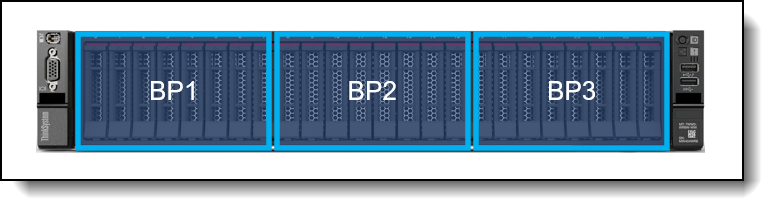
Figure 14. Backplane numbering
| Cfg | Front | Mid | Rear | Backplane and cable kits required (all required) | ||||||
|---|---|---|---|---|---|---|---|---|---|---|
| SAS/ SATA |
Any Bay |
NVMe | 3.5" SAS |
2.5" SAS |
2.5" NVMe |
3.5" SAS |
2.5" SAS |
2.5" Any |
||
| 10 | 8 | 0 | 0 | 0 | 0 | 0 | 0 | 0 | 0 |
|
| 11 | 0 | 8 | 0 | 0 | 0 | 0 | 0 | 0 | 0 |
|
| 12 | 0 | 0 | 8 | 0 | 0 | 0 | 0 | 0 | 0 |
|
| 13 | 6 | 2 | 0 | 0 | 0 | 0 | 0 | 0 | 0 |
|
| 14 | 16 | 0 | 0 | 0 | 0 | 0 | 0 | 0 | 0 |
|
| 15 | 0 | 8 | 8 | 0 | 0 | 0 | 0 | 0 | 0 |
|
| 16 | 0 | 0 | 16 | 0 | 0 | 0 | 0 | 0 | 0 |
|
| 16 Tri-mode | 0 | 16 | 0 | 0 | 0 | 0 | 0 | 0 | 0 |
|
| 17 | 8 | 8 | 0 | 0 | 0 | 0 | 0 | 0 | 0 |
|
| 18 | 8 | 0 | 8 | 0 | 0 | 0 | 0 | 0 | 0 |
|
| 19 | 12 | 0 | 4 | 0 | 0 | 0 | 0 | 0 | 0 |
|
| 20 | 16 | 8 | 0 | 0 | 0 | 0 | 0 | 0 | 0 |
|
| 21 | 16 | 0 | 8 | 0 | 0 | 0 | 0 | 0 | 0 |
|
| 22 | 24 | 0 | 0 | 0 | 0 | 0 | 0 | 0 | 0 |
|
| 22A | 24 | 0 | 0 | 0 | 0 | 0 | 0 | 0 | 0 |
|
| 23 | 0 | 0 | 24 | 0 | 0 | 0 | 0 | 0 | 0 |
|
| 23 Tri-mode | 0 | 24 | 0 | 0 | 0 | 0 | 0 | 0 | 0 |
|
| 24 | 0 | 8 | 16 | 0 | 0 | 0 | 0 | 0 | 0 |
|
| 24B | 8 | 0 | 16 | 0 | 0 | 0 | 0 | 0 | 0 |
|
| 25 |
|
|||||||||
| 26 | 24 | 0 | 0 | 0 | 0 | 0 | 0 | 4 | 0 |
|
| 26A | 24 | 0 | 0 | 0 | 0 | 0 | 0 | 4 | 0 |
|
| 27 | 24 | 0 | 0 | 0 | 4 | 0 | 0 | 0 | 0 |
|
| 29 | 24 | 0 | 0 | 0 | 0 | 0 | 0 | 8 | 0 |
|
| 29A | 24 | 0 | 0 | 0 | 0 | 0 | 0 | 8 | 0 |
|
| 30 | 0 | 0 | 24 | 0 | 0 | 8 | 0 | 0 | 0 |
|
| 31 | 24 | 0 | 0 | 0 | 8 | 0 | 0 | 0 | 0 |
|
| 32 | 24 | 0 | 0 | 0 | 8 | 0 | 0 | 4 | 0 |
|
| 33 | 24 | 0 | 0 | 0 | 8 | 0 | 0 | 8 | 0 |
|
When adding drive bays, you will also need to add the appropriate storage controller(s). Consult the tables in the Storage configurations section to determine what controller sections are supported and what additional controllers you will need. Controllers are described in the Controllers for internal storage section.
Upgrades to Retimer adapters
If you are upgrading to a configuration that includes a Retimer adapter (see the Detailed tables in the Storage configurations section), then you will need to also order one of the following cable kits.
| Part number | Description | Quantity required |
|---|---|---|
| 4X97A85860 | ThinkSystem SR665 V3 32x2.5" PCIe Gen4 NVME Retimer Cable Option Kit | 1 |
| 4X97A85859 | ThinkSystem SR665 V3 24x2.5" PCIe Gen4 NVME Retimer Cable Option Kit | 1 |
Upgrades to an Internal (CFF) HBA/RAID adapter
If you want to add an internal (CFF) storage adapter (HBA, RAID adapter or SAS expander) to a configuration, you will need to order the cable kit as listed in the following table. Suitable upgrades are either replacing an existing adapter in a rear PCIe slot, or adding the CFF adapter to a server without any storage adapter installed.
The cable kit to order is listed in the following table.
| Part number | Description | Quantity required |
|---|---|---|
| 4X97A85177 | ThinkSystem SR665 V3 Internal HBA/RAID Adapter Cable Option Kit | 1 |
RAID flash power module (supercap) support
If you plan to add one of the RAID adapters that includes a RAID flash power module (supercap) as a field upgrade, then you may also need to order a Supercap installation kit for the supercap, depending on the location where the supercap will be installed. For CTO orders, the components needed are automatically derived when you select the RAID adapter.
The adapters that this applies to are as follows:
- Any supported RAID 9350 adapter
- Any supported RAID 940 adapter
The location of the supercaps depends on the mid-chassis drive cage used in the server, as shown in the following table.
| Mid drive cage | Supercaps supported |
Location of supercaps | Supercap holder |
|---|---|---|---|
| No mid drive cage | 4 | Mounted on the air baffle | Not needed |
| 2.5-inch drives | 2 | Mounted on the left side of the mid drive cage | Integrated into the left side of the 2.5-inch mid drive cage |
| 3.5-inch drives | 1 | Mounted under the system fan cage | Included with ThinkSystem SR665 V3 Middle 4x3.5" SAS/SATA Backplane Option Kit (4XH7A85892) or order separately (see below) |
For 3.5-inch drive bay configurations, if the server already has 3.5-inch mid-chassis drive bays, then the supercap holder is already present under the system fan cages. If you plan to add 3.5-inch mid-chassis drive bays by adding ThinkSystem SR665 V3 Middle 4x3.5" SAS/SATA Backplane Option Kit (4XH7A85892), then the supercap holder is part of the option kit.
7mm drives
The SR665 V3 supports two 7mm drives, either both SATA or both NVMe, at the rear of the server. These drives go in place of either PCIe slot 3 (Riser 1) or PCIe slot 6 (Riser 2) as shown in the following figure.
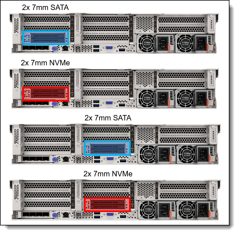
Figure 15. Rear 7mm drive bay configurations
For CTO orders, the configuration includes the drive bays and the cage the the drive bays are mounted on to.The cage required depends on where the 7mm drives are located (Riser 1 or Riser 2) and whether there are PCIe slots above the 7mm drive bays. The following table lists the ordering information.
Tip for 4x 3.5-inch rear drives: If you wish to configure 4x 3.5-inch rear drives plus 7mm drives in a CTO configuration, the 7mm drives will install in slot 6. You should specify riser card BLKP for Riser 1 and then leave Riser 2 without a riser selected.
| Feature code |
Description | SATA drives |
NVMe drives |
RAID | Maximum supported |
Windows 10/11 support |
|---|---|---|---|---|---|---|
| Backplane - 7mm drives | ||||||
| BU0N | ThinkSystem 7mm SATA/NVMe 2-Bay Rear Enablement Kit v2 | Yes | Yes (x1 lane) | Optional | 1 | No |
| B8P3 | ThinkSystem 2U 7mm Drive Kit w/ NVMe RAID | No | Yes (x1 lane) | Integrated (Marvell) | 1 | No |
| BYFG | ThinkSystem 7mm SATA/NVMe 2-Bay Rear Hot-Swap RAID Enablement Kit | Yes | Yes (x1 lane) | Integrated (Broadcom) | 1 | Supported |
The following table lists the PCIe RAID adapters that can be used to add RAID functionality to ThinkSystem 7mm SATA/NVMe 2-Bay Rear Enablement Kit v2 (BU0N)
| Feature code |
Description | Maximum supported |
|---|---|---|
| Hardware RAID support for ThinkSystem 7mm SATA/NVMe 2-Bay Rear Enablement Kit v2 (BU0N) | ||
| BT7N | ThinkSystem RAID 5350-8i for M.2/7mm SATA Boot Enablement | 1 |
| BT7P | ThinkSystem RAID 540-8i for M.2/7mm NVMe Boot Enablement | 1 |
The use of the 7mm rear drive bays has the following configuration rules:
- The 7mm rear drive kit is supported in either slot 3 or slot 6 but not both at the same time.
- M.2 and 7mm are mutually exclusive: they are not supported together in the same configuration
- For ThinkSystem 7mm SATA/NVMe 2-Bay Rear Enablement Kit v2 (feature BU0N):
- The 7mm drive bays support either SATA drives or NVMe drives but not both. You specify SATA or NVMe in the configurator using feature codes BTTV (SATA) or BTTW (NVMe).
- If RAID support is required, select feature code BS7A in the configurator to enable RAID
- The support of RAID-1 with the 7mm drives requires an additional RAID adapter that is installed in PCIe slot 2 or slot 3:
- RAID support for 7mm SATA drives requires a RAID 5350-8i adapter (feature BT7N)
- RAID support for 7mm NVMe drives requires a RAID 540-8i adapter operating in Tri-Mode (feature BT7P)
- The RAID adapter used for 7mm drive support cannot be configured for use with other drive bays (not even with M.2)
- If RAID support is not required, the 7mm drives connect to an onboard port; No additional adapter is required
- For ThinkSystem 2U 7mm Drive Kit w/ NVMe RAID (feature B8P3)
- The adapter only supports NVMe drives
- RAID functionality is integrated into the 7mm adapter using a Marvell 88NR2241 NVMe RAID Controller
- For ThinkSystem 7mm SATA/NVMe 2-Bay Rear Hot-Swap RAID Enablement Kit (feature BYFG)
- The adapter supports either SATA or NVMe drives
- RAID functionality is integrated into the 7mm adapter using a Broadcom RAID Controller
7mm drive field upgrades
For field upgrades, using the following ordering information. The kits include two cages for use depending on your PCIe slot configuration. The cages are for either Riser 1 or Riser 2. The part numbers also include the cables necessary to connect the 7mm backplane to either the system board or RAID adapter.
| Part number | Description | Purpose |
|---|---|---|
| 7mm Enablement Kits | ||
| 4XH7A85898 |
ThinkSystem SR665 V3 Rear 2x7mm SATA/NVMe Enablement Kit
|
7mm drive bays for SATA or NVMe drive support with no RAID support (does not include cables needed for RAID support with a separate adapter) |
| 4XH7A85899 |
ThinkSystem SR665 V3 Rear 2x7mm SATA/NVMe RAID Enablement Kit
|
7mm drive bays for SATA or NVMe drives, plus cables for use with a RAID adapter. Requires a separate RAID adapter for RAID support. |
| 4XH7A88742 |
ThinkSystem SR665 V3 Rear 2x7mm NVMe RAID Enablement Kit
|
7mm drive bays for NVMe drive support. RAID support is integrated into the adapter using an onboard Marvell 88NR2241 NVMe RAID controller. |
| 4XH7A93167 |
ThinkSystem SR665 V3/SR655 V3 7mm RAID B540p-2HS SATA/NVMe Enablement Kit
|
7mm drive bays for SATA or NVMe drive support. RAID support is integrated into the adapter using an onboard Broadcom RAID controller. |
| RAID adapters for optional 7mm HW RAID support (for use with 4XH7A85899) | ||
| 4Y37A72482 | ThinkSystem RAID 5350-8i PCIe 12Gb Adapter | RAID adapter needed for SATA RAID-1 with 2x 7mm SATA drives |
| 4Y37A78834 | ThinkSystem RAID 540-8i PCIe Gen4 12Gb Adapter |
RAID adapter needed for NVMe RAID-1 with 2x 7mm NVMe drives Tip: Once the 540-8i adapter is installed, it will need to be configured to operate in Tri-mode to enable NVMe RAID. |
M.2 drives
The SR665 V3 supports one or two M.2 form-factor SATA or NVMe drives for use as an operating system boot solution or as additional storage.
The M.2 drives install into an M.2 module which is mounted horizontally in the server:
- In servers without mid-chassis drives, the M.2 module is mounted on the air baffle
- With a mid-chassis drive cage (2.5-inch or 3.5-inch), the M.2 module is mounted on the drive cage, as shown in the Mid drive bays section.
The supported M.2 modules are listed in the following table. For field upgrades see the M.2 field upgrades section below.
| Part number |
Feature code |
Description | SATA drives |
NVMe drives |
RAID | Maximum supported |
Windows 10/11 support |
|---|---|---|---|---|---|---|---|
| 4Y37A09738 | B5XJ | ThinkSystem M.2 SATA/NVMe 2-Bay Enablement Kit | Yes | Yes (x1 lane) | No | 1 | Supported |
| 4Y37A79663 | BM8X | ThinkSystem M.2 SATA/x4 NVMe 2-Bay Adapter | Yes | Yes (x4 lanes) | Optional | 1 | Supported |
| 4Y37A09750 | B8P9 | ThinkSystem M.2 NVMe 2-Bay RAID Adapter | No | Yes (x1 lane) | Integrated (Marvell) | 1 | No |
| 4Y37A90063 | BYFF | ThinkSystem M.2 RAID B540i-2i SATA/NVMe Adapter | Yes | Yes (x1 lane) | Integrated (Broadcom) | 1 | Supported |
The ThinkSystem M.2 SATA/x4 NVMe 2-Bay Adapter optionally supports RAID with the addition of a separate RAID adapter is required. For CTO orders, ordering information is listed in the following table to derive the required RAID adapter.
| Feature code |
Description | RAID support |
Maximum supported |
Windows 10/11 support |
|---|---|---|---|---|
| BT7N | ThinkSystem RAID 5350-8i for M.2/7mm SATA Boot Enablement | SATA | 1 | Supported |
| BT7P | ThinkSystem RAID 540-8i for M.2/7mm NVMe Boot Enablement | NVMe | 1 | Supported |
Configuration notes:
- M.2 is not supported with all storage configurations - see Storage configurations for details.
- M.2 and 7mm are mutually exclusive: they are not supported together in the same configuration
- For field upgrades, an additional cable is needed as described in the M.2 field upgrades section below
- For ThinkSystem M.2 SATA/x4 NVMe 2-Bay Adapter (4Y37A79663):
- RAID support is implemented with the use of an additional RAID adapter installed in a slot
- The adapter is not supported with Riser 3 or front PCIe slots
- If RAID support is not required, the M.2 adapter connects to an onboard port. No additional adapter is required
- The support of RAID-1 with the M.2 drives requires an additional RAID adapter that is installed in PCIe slot 2 or slot 3:
- RAID support for M.2 SATA drives requires a RAID 5350-8i adapter (feature BT7N)
- RAID support for M.2 NVMe drives requires a RAID 540-8i adapter operating in Tri-Mode (feature BT7P)
- The RAID adapter used for M.2 drive support cannot be configured for use with other drive bays (not even with 7mm)
- For ThinkSystem M.2 NVMe 2-Bay RAID Adapter (4Y37A09750):
- RAID is implemented using an onboard Marvell 88NR2241 NVMe RAID controller
- For ThinkSystem M.2 RAID B540i-2i SATA/NVMe Adapter (4Y37A90063):
- RAID is implemented using an onboard Broadcom RAID controller
Supported drives are listed in the Internal drive options section.
The ThinkSystem M.2 SATA/NVMe 2-Bay Enablement Kit has the following features:
- Supports one or two M.2 drives, either SATA or NVMe
- When two drives installed, they must be either both SATA or both NVMe
- Support 42mm, 60mm, 80mm and 110mm drive form factors (2242, 2260, 2280 and 22110)
- On the SR665 V3, no RAID support
- Either 6Gbps SATA or PCIe 3.0 x1 interface to the drives depending on the drives installed
- Supports monitoring and reporting of events and temperature through I2C
- Firmware update via Lenovo firmware update tools
The ThinkSystem M.2 SATA/x4 NVMe 2-Bay Adapter has the following features:
- Supports one or two M.2 drives, either SATA or NVMe
- When two drives installed, they must be either both SATA or both NVMe
- Support 42mm, 60mm, 80mm and 110mm drive form factors (2242, 2260, 2280 and 22110)
- No onboard RAID; RAID functionality is provided by a separate adapter (SATA or NVMe)
- Either 6Gbps SATA or PCIe 4.0 x4 interface to the drives depending on the drives installed
- Supports monitoring and reporting of events and temperature through I2C
- Firmware update via Lenovo firmware update tools
- When connected to a separate PCIe RAID adapter, supports SED drive encryption via the RAID adapter, otherwise no SED support
The ThinkSystem M.2 NVMe 2-Bay RAID Adapter (4Y37A09750) has the following features:
- Supports one or two NVMe M.2 drives
- Support 42mm, 60mm, 80mm and 110mm drive form factors (2242, 2260, 2280 and 22110)
- RAID support via an onboard Marvell 88NR2241 NVMe RAID Controller
- With 1 drive, supports single-drive RAID-0
- With 2 drives, supports 2-drive RAID-0, 2-drive RAID-1, or two single-drive RAID-0 arrays
- PCIe 3.0 x2 host interface; PCIe 3.0 x1 connection to each drive
- Management and configuration support via UEFI and OS-based tools
- Supports monitoring and reporting of events and temperature through I2C
- Firmware update via Lenovo firmware update tools
- No support for SED drive encryption
The ThinkSystem M.2 RAID B540i-2i SATA/NVMe Adapter (4Y37A90063) has the following features:
- Supports one or two M.2 drives, either SATA or NVMe
- Support 42mm, 60mm, 80mm and 110mm drive form factors (2242, 2260, 2280 and 22110)
- RAID support via an onboard Broadcom SAS3808N RAID Controller
- With 1 drive, supports JBOD
- With 2 drives, supports 2-drive RAID-0, 2-drive RAID-1, or JBOD
- PCIe 4.0 x2 host interface; PCIe 4.0 x1 connection to each drive
- Management and configuration support via UEFI and OS-based tools
- Supports monitoring and reporting of events and temperature
- Firmware update via Lenovo firmware update tools
- Supports SED drive encryption
M.2 field upgrades
For field upgrades, the SR665 V3 also requires additional cables necessary to connect the M.2 to either the system board or RAID adapter. Ordering information is listed in the following table.
| Part number | Description |
|---|---|
| M.2 Cable Kit - cables for use with RAID adapters or with onboard connectivity | |
| 4X97A87126 | ThinkSystem SR665 V3 M.2 Enablement Cable Option Kit |
| RAID adapters for M.2 RAID support (ThinkSystem M.2 SATA/x4 NVMe 2-Bay Adapter only) | |
| 4Y37A72482 | ThinkSystem RAID 5350-8i PCIe 12Gb Adapter (SATA M.2 support) |
| 4Y37A78834 | ThinkSystem RAID 540-8i PCIe Gen4 12Gb Adapter (NVMe M.2 support using Tri-Mode) |
SED encryption key management with SKLM
The server supports self-encrypting drives (SEDs) as listed in the Internal drive options section. To effectively manage a large deployment of these drives in Lenovo servers, IBM Security Key Lifecycle Manager (SKLM) offers a centralized key management solution. A Lenovo Feature on Demand (FoD) upgrade is used to enable this SKLM support in the management processor of the server.
The following table lists the part numbers and feature codes for the upgrades.
| Part number | Feature code | Description |
|---|---|---|
| Security Key Lifecycle Manager - FoD (United States, Canada, Asia Pacific, and Japan) | ||
| 00D9998 | A5U1 | SKLM for System x/ThinkSystem w/SEDs - FoD per Install with 1 year S&S |
| 00D9999 | AS6C | SKLM for System x/ThinkSystem w/SEDs - FoD per Install with 3 year S&S |
| Security Key Lifecycle Manager - FoD (Latin America, Europe, Middle East, and Africa) | ||
| 00FP648 | A5U1 | SKLM for System x/ThinkSystem w/SEDs - FoD per Install with 1 year S&S |
| 00FP649 | AS6C | SKLM for System x/ThinkSystem w/SEDs - FoD per Install with 3 year S&S |
The IBM Security Key Lifecycle Manager software is available from Lenovo using the ordering information listed in the following table.
| Part number | Description |
|---|---|
| 7S0A007FWW | IBM Security Key Lifecycle Manager Basic Edition Install License + SW Subscription & Support 12 Months |
| 7S0A007HWW | IBM Security Key Lifecycle Manager For Raw Decimal Terabyte Storage Resource Value Unit License + SW Subscription & Support 12 Months |
| 7S0A007KWW | IBM Security Key Lifecycle Manager For Raw Decimal Petabyte Storage Resource Value Unit License + SW Subscription & Support 12 Months |
| 7S0A007MWW | IBM Security Key Lifecycle Manager For Usable Decimal Terabyte Storage Resource Value Unit License + SW Subscription & Support 12 Months |
| 7S0A007PWW | IBM Security Key Lifecycle Manager For Usable Decimal Petabyte Storage Resource Value Unit License + SW Subscription & Support 12 Months |
Controllers for internal storage
The SR665 V3 offers a variety of controller options for internal drives:
- For 2.5-inch and 3.5-inch drives:
- Onboard SATA ports (feature AVUX)
- Onboard NVMe ports (feature BC4V)
- NVMe switch and retimer adapters (PCIe slot-based)
- RAID adapters and HBAs for SAS/SATA drives (PCIe slot-based)
- RAID adapters, SAS Expander, and HBAs for SAS/SATA drives (cabled in a dedicated space)
- For 7mm drive bays in the rear of the server (see the 7mm drives section)
- SATA controller integrated into the 7mm drive bay enclosure
- NVMe controller integrated into the 7mm drive bay enclosure
- For M.2 drives internal to the server (see M.2 drives section)
- SATA controller integrated on the M.2 SATA 2-Bay RAID Enablement Kit
- NVMe controller integrated on the M.2 NVMe 2-Bay RAID Enablement Kit
As well as supporting RAID adapters and HBAs that install in a PCIe slot, the SR665 V3 with 2.5-inch front drive bays supports a custom form factor (CFF) adapter that is mounted in the server and cabled to one of the onboard NVMe ports. These Internal Adapters are not supported with 3.5-inch front drives due to a lack of physical space.
The following table lists the adapters used for the internal storage of the server.
| Part number |
Feature code |
Description | Power module (supercap) |
PCIe lanes |
Max qty |
Slots supported |
Windows 10/11 support |
|---|---|---|---|---|---|---|---|
| Onboard controllers | |||||||
| CTO only | AVUX | Onboard SATA AHCI Mode | No | 1 | N/A | Supported | |
| CTO only | BC4V | Non RAID NVMe (Onboard NVMe) | No | 1 | N/A | Supported | |
| RAID controllers - PCIe Gen 3 | |||||||
| 4Y37A72482 | BJHK | ThinkSystem RAID 5350-8i PCIe 12Gb Adapter | No | Gen3 x8 | 3 | 1,2,3,4,5,6 | Supported |
| 4Y37A72483 | BJHL | ThinkSystem RAID 9350-8i 2GB Flash PCIe 12Gb Adapter | Included | Gen3 x8 | 3 | 1,2,3,4,5,6 | Supported |
| 4Y37A72484 | BJHM | ThinkSystem RAID 9350-8i 2GB Flash PCIe 12Gb Internal Adapter | Included | Gen3 x8 | 1 | Internal‡ | Supported |
| 4Y37A72485 | BJHN | ThinkSystem RAID 9350-16i 4GB Flash PCIe 12Gb Adapter | Included | Gen3 x8 | 2 | 1,2,3,4,5,6 | Supported |
| 4Y37A72486 | BJHP | ThinkSystem RAID 9350-16i 4GB Flash PCIe 12Gb Internal Adapter | Included | Gen3 x8 | 1 | Internal‡ | Supported |
| RAID controllers - PCIe Gen 4 | |||||||
| 4Y37A78834 | BMFT | ThinkSystem RAID 540-8i PCIe Gen4 12Gb Adapter | No | Gen4 x8 | 3 | 1,2,3,4,5,6 | Supported |
| 4Y37A78835 | BNAX | ThinkSystem RAID 540-16i PCIe Gen4 12Gb Adapter | No | Gen4 x8 | 2 | 1,2,3,4,5,6 | Supported |
| 4Y37A09728† | B8NY | ThinkSystem RAID 940-8i 4GB Flash PCIe Gen4 12Gb Adapter | Included | Gen4 x8 | 3 | 1,2,3,4,5,6 | Supported |
| 4Y37A78600† | BM35 | ThinkSystem RAID 940-16i 4GB Flash PCIe Gen4 12Gb Adapter | Included | Gen4 x8 | 2 | 1,2,3,4,5,6 | Supported |
| 4Y37A09730† | B8NZ | ThinkSystem RAID 940-16i 8GB Flash PCIe Gen4 12Gb Adapter | Included | Gen4 x8 | 2 | 1,2,3,4,5,6 | Supported |
| 4Y37A09735 | B8P0 | ThinkSystem RAID 940-16i 8GB Flash PCIe Gen4 12Gb Internal Adapter | Included | Gen4 x8 | 1 | Internal‡ | Supported |
| 4Y37A09733 | B8P8 | ThinkSystem RAID 940-32i 8GB Flash PCIe Gen4 12Gb Adapter | Included | Gen4 x8 | 1 | 1,2,3,4,5,6 | Supported |
| SAS HBA - PCIe Gen 3 | |||||||
| 4Y37A72480 | BJHH | ThinkSystem 4350-8i SAS/SATA 12Gb HBA | No | Gen3 x8 | 3 | 1,2,3,4,5,6 | No |
| 4Y37A72481 | BJHJ | ThinkSystem 4350-16i SAS/SATA 12Gb HBA | No | Gen3 x8 | 2 | 1,2,3,4,5,6 | No |
| SAS HBA - PCIe Gen 4 | |||||||
| 4Y37A78601 | BM51 | ThinkSystem 440-8i SAS/SATA PCIe Gen4 12Gb HBA | No | Gen4 x8 | 3 | 1,2,3,4,5,6 | No |
| 4Y37A78602 | BM50 | ThinkSystem 440-16i SAS/SATA PCIe Gen4 12Gb HBA | No | Gen4 x8 | 2 | 1,2,3,4,5,6 | No |
| 4Y37A09725 | B8P1 | ThinkSystem 440-16i SAS/SATA PCIe Gen4 12Gb Internal HBA | No | Gen4 x8 | 1 | Internal‡ | No |
| SAS expanders | |||||||
| 4Y37A09736 | B8P6 | ThinkSystem 48 port 12Gb Internal Expander | No | Gen3 x8 | 1 | Internal‡ | Supported |
| NVMe adapters - PCIe Gen 4 | |||||||
| 4C57A65446 | B98C | ThinkSystem 4-Port PCIe Gen4 NVMe Retimer Adapter | No | Gen4 x16 | 3 | 1,2,3,4,5 | Supported |
| 4Y37A09728† | BGM1 | ThinkSystem RAID 940-8i 4GB Flash PCIe Gen4 12Gb Adapter for U.3 | Included | Gen4 x8 | 3 | 1,2,3,4,5,6 | Supported |
| 4Y37A78600† | BM36 | ThinkSystem RAID 940-16i 4GB Flash PCIe Gen4 12Gb Adapter for U.3 | Included | Gen4 x8 | 1 | 1,2,3,4,5,6 | Supported |
| 4Y37A09730† | BDY4 | ThinkSystem RAID 940-16i 8GB Flash PCIe Gen4 12Gb Adapter for U.3 | Included | Gen4 x8 | 1 | 1,2,3,4,5,6 | Supported |
‡ These custom form factor (CFF) adapters are only supported with 2.5-inch front drive bays. Not supported in configurations with 3.5-inch front drive bays.
† Adapter also supports PCIe 4.0 x1 connectivity to NVMe drives (requires NVMe drives with U.3 interface)
Configuration notes:
- Supercap support limits the number of RAID adapters installable: The table lists whether the adapter includes a power module (supercap) to power the flash memory. The server supports between 1 and 4 supercaps depending on the server configuration as described in the RAID flash power module (supercap) support section. The number of supercaps supported also determines the maximum number of RAID adapters with flash that can be installed in the server.
- Field upgrades: If you are adding a RAID adapter with supercap to the server as a field upgrade, you may need a supercap holder as described in the RAID flash power module (supercap) support section.
- 7mm drive support: The storage adapters listed in the table below do not provide connectivity to the 7mm drive bays. The 7mm drives have their own independent RAID controller. See the 7mm drives section for details.
- E810 Ethernet and X350 RAID/HBAs: The use of both an Intel E810 network adapter and an X350 HBA/RAID adapter (9350, 5350 and 4350) is currently not supported in ThinkSystem servers. For details see Support Tip HT513226. Planned support for this combination of adapters is 2Q/2024.
The RAID 940-8i and RAID 940-16i adapters also support NVMe through a feature named Tri-Mode support (or Trimode support). This feature enables the use of NVMe U.3 drives at the same time as SAS and SATA drives. Tri-Mode requires an AnyBay backplane. Cabling of the controller to the backplanes is the same as with SAS/SATA drives, and the NVMe drives are connected via a PCIe x1 link to the controller.
NVMe drives connected using Tri-Mode support provide better performance than SAS or SATA drives: A SATA SSD has a data rate of 6Gbps, a SAS SSD has a data rate of 12Gbps, whereas an NVMe U.3 Gen 4 SSD with a PCIe x1 link will have a data rate of 16Gbps. NVMe drives typically also have lower latency and higher IOPS compared to SAS and SATA drives. Tri-Mode is supported with U.3 NVMe drives in either 2.5-inch and 3.5-inch form factor and requires an AnyBay backplane.
Tri-Mode requires U.3 drives: Only NVMe drives with a U.3 interface are supported. U.2 drives are not supported. See the Internal drive options section for the U.3 drives supported by the server.
The onboard SATA controller has the following features:
- Controller integrated into the AMD processor
- JBOD only; no RAID support
- Supports up to 20 SATA drives in the SR665 V3 (16 with one processor)
- Supports HDDs and SSDs; can be mixed
The onboard NVMe support has the following features:
- Controller integrated into the AMD processor
- Supports up to 20x NVMe drives direct connected to onboard ports; additional drives through retimer/switch adapters
- Each drive has PCIe 5.0 x4 host interface
- Supports JBOD - Intel and non-Intel NVMe SSDs
- No support for RAID
For specifications about the RAID adapters and HBAs supported by the SR665 V3, see the ThinkSystem RAID Adapter and HBA Reference, available from:
https://lenovopress.lenovo.com/lp1288-thinksystem-raid-adapter-and-hba-reference#sr665-v3-support=SR665%2520V3
For more information about each of the adapters, see the product guides in the RAID adapters or HBA sections of the Lenovo Press web site:
https://lenovopress.com/servers/options/raid
https://lenovopress.com/servers/options/hba
Internal drive options
The following tables list the drive options for internal storage of the server.
2.5-inch hot-swap drives:
- 2.5-inch hot-swap 12 Gb SAS HDDs
- 2.5-inch hot-swap 24 Gb SAS SSDs
- 2.5-inch hot-swap 12 Gb SAS SSDs
- 2.5-inch hot-swap 6 Gb SATA SSDs
- 2.5-inch hot-swap PCIe 5.0 NVMe SSDs
- 2.5-inch hot-swap PCIe 4.0 NVMe SSDs
2.5-inch 7mm hot-swap drives:
3.5-inch hot-swap drives:
M.2 drives:
M.2 drive support: The use of M.2 drives requires an additional adapter as described in the M.2 drives subsection.
SED support: The tables include a column to indicate which drives support SED encryption. The encryption functionality can be disabled if needed. Note: Not all SED-enabled drives have "SED" in the description.
| Part number | Feature code |
Description | SED support |
Max Qty |
|---|---|---|---|---|
| 2.5-inch hot-swap HDDs - 12 Gb SAS 15K | ||||
| 7XB7A00021 | AULV | ThinkSystem 2.5" 300GB 15K SAS 12Gb Hot Swap 512n HDD | No | 40 |
| 7XB7A00022 | AULW | ThinkSystem 2.5" 600GB 15K SAS 12Gb Hot Swap 512n HDD | No | 40 |
| 7XB7A00023 | AULX | ThinkSystem 2.5" 900GB 15K SAS 12Gb Hot Swap 512e HDD | No | 40 |
| 2.5-inch hot-swap HDDs - 12 Gb SAS 10K | ||||
| 7XB7A00025 | AULZ | ThinkSystem 2.5" 600GB 10K SAS 12Gb Hot Swap 512n HDD | No | 40 |
| 7XB7A00027 | AUM1 | ThinkSystem 2.5" 1.2TB 10K SAS 12Gb Hot Swap 512n HDD | No | 40 |
| 7XB7A00028 | AUM2 | ThinkSystem 2.5" 1.8TB 10K SAS 12Gb Hot Swap 512e HDD | No | 40 |
| 4XB7A83970 | BRG7 | ThinkSystem 2.5" 2.4TB 10K SAS 12Gb Hot Swap 512e HDD v2 | No | 40 |
| 2.5-inch hot-swap SED HDDs - 12 Gb SAS 10K | ||||
| 7XB7A00031 | AUM5 | ThinkSystem 2.5" 600GB 10K SAS 12Gb Hot Swap 512n HDD SED | Support | 40 |
| 7XB7A00033 | B0YX | ThinkSystem 2.5" 1.2TB 10K SAS 12Gb Hot Swap 512n HDD SED | Support | 40 |
| 4XB7A84038 | BRG8 | ThinkSystem 2.5" 2.4TB 10K SAS 12Gb Hot Swap 512e HDD FIPS v2 | Support | 40 |
| Part number | Feature code |
Description | SED support |
Max Qty |
|---|---|---|---|---|
| 2.5-inch hot-swap SSDs - 24 Gb SAS - Mixed Use/Mainstream (3-5 DWPD) | ||||
| 4XB7A80340 | BNW8 | ThinkSystem 2.5" PM1655 800GB Mixed Use SAS 24Gb HS SSD | Support | 40 |
| 4XB7A80341 | BNW9 | ThinkSystem 2.5" PM1655 1.6TB Mixed Use SAS 24Gb HS SSD | Support | 40 |
| 4XB7A80342 | BNW6 | ThinkSystem 2.5" PM1655 3.2TB Mixed Use SAS 24Gb HS SSD | Support | 40 |
| 4XB7A80343 | BP3K | ThinkSystem 2.5" PM1655 6.4TB Mixed Use SAS 24Gb HS SSD | Support | 40 |
| 2.5-inch hot-swap SSDs - 24 Gb SAS - Read Intensive/Entry/Capacity (<3 DWPD) | ||||
| 4XB7A80318 | BNWC | ThinkSystem 2.5" PM1653 960GB Read Intensive SAS 24Gb HS SSD | Support | 40 |
| 4XB7A80319 | BNWE | ThinkSystem 2.5" PM1653 1.92TB Read Intensive SAS 24Gb HS SSD | Support | 40 |
| 4XB7A80320 | BNWF | ThinkSystem 2.5" PM1653 3.84TB Read Intensive SAS 24Gb HS SSD | Support | 40 |
| 4XB7A80321 | BP3E | ThinkSystem 2.5" PM1653 7.68TB Read Intensive SAS 24Gb HS SSD | Support | 40 |
| 4XB7A80322 | BP3J | ThinkSystem 2.5" PM1653 15.36TB Read Intensive SAS 24Gb HS SSD | Support | 40 |
| 4XB7A80323 | BP3D | ThinkSystem 2.5" PM1653 30.72TB Read Intensive SAS 24Gb HS SSD | Support | 40 |
| Part number | Feature code |
Description | SED support |
Max Qty |
|---|---|---|---|---|
| 2.5-inch hot-swap SSDs - 12 Gb SAS - Write Intensive/Performance (10+ DWPD) | ||||
| 4XB7A83214 | BR10 | ThinkSystem 2.5" Nytro 3750 400GB Write Intensive SAS 12Gb HS SSD | Support | 40 |
| 4XB7A83215 | BR0Z | ThinkSystem 2.5" Nytro 3750 800GB Write Intensive SAS 12Gb HS SSD | Support | 40 |
| 4XB7A83216 | BR0Y | ThinkSystem 2.5" Nytro 3750 1.6TB Write Intensive SAS 12Gb HS SSD | Support | 40 |
| 4XB7A83217 | BR0X | ThinkSystem 2.5" Nytro 3750 3.2TB Write Intensive SAS 12Gb HS SSD | Support | 40 |
| 4XB7A70006 | BG07 | ThinkSystem 2.5" Nytro 3732 400GB Performance SAS 12Gb Hot Swap SSD | No | 40 |
| 4XB7A70005 | BG06 | ThinkSystem 2.5" Nytro 3732 800GB Performance SAS 12Gb Hot Swap SSD | No | 40 |
| 4XB7A70004 | BG05 | ThinkSystem 2.5" Nytro 3732 1.6TB Performance SAS 12Gb Hot Swap SSD | No | 40 |
| 4XB7A70003 | BG04 | ThinkSystem 2.5" Nytro 3732 3.2TB Performance SAS 12Gb Hot Swap SSD | No | 40 |
| Part number | Feature code |
Description | SED support |
Max Qty |
|---|---|---|---|---|
| 2.5-inch hot-swap SSDs - 6 Gb SATA - Mixed Use/Mainstream (3-5 DWPD) | ||||
| 4XB7A90884 | BYM2 | ThinkSystem 2.5" Multi Vendor 480GB Mixed Use SATA 6Gb HS SSD v2 | No | 40 |
| 4XB7A90885 | BYM4 | ThinkSystem 2.5" Multi Vendor 960GB Mixed Use SATA 6Gb HS SSD v2 | No | 40 |
| 4XB7A90886 | BYM5 | ThinkSystem 2.5" Multi Vendor 1.92TB Mixed Use SATA 6Gb HS SSD v2 | No | 40 |
| 4XB7A90887 | BYM6 | ThinkSystem 2.5" Multi Vendor 3.84TB Mixed Use SATA 6Gb HS SSD v2 | No | 40 |
| 4XB7A82289 | BQ21 | ThinkSystem 2.5" 5400 MAX 480GB Mixed Use SATA 6Gb HS SSD | Support | 40 |
| 4XB7A82290 | BQ24 | ThinkSystem 2.5" 5400 MAX 960GB Mixed Use SATA 6Gb HS SSD | Support | 40 |
| 4XB7A82291 | BQ22 | ThinkSystem 2.5" 5400 MAX 1.92TB Mixed Use SATA 6Gb HS SSD | Support | 40 |
| 4XB7A82292 | BQ23 | ThinkSystem 2.5" 5400 MAX 3.84TB Mixed Use SATA 6Gb HS SSD | Support | 40 |
| 4XB7A17125 | BA7Q | ThinkSystem 2.5" S4620 480GB Mixed Use SATA 6Gb HS SSD | No | 40 |
| 4XB7A17126 | BA4T | ThinkSystem 2.5" S4620 960GB Mixed Use SATA 6Gb HS SSD | No | 40 |
| 4XB7A17127 | BA4U | ThinkSystem 2.5" S4620 1.92TB Mixed Use SATA 6Gb HS SSD | No | 40 |
| 4XB7A17128 | BK7L | ThinkSystem 2.5" S4620 3.84TB Mixed Use SATA 6Gb HS SSD | No | 40 |
| 2.5-inch hot-swap SSDs - 6 Gb SATA - Read Intensive/Entry (<3 DWPD) | ||||
| 4XB7A90872 | BYLQ | ThinkSystem 2.5" Multi Vendor 240GB Read Intensive SATA 6Gb HS SSD v2 | No | 40 |
| 4XB7A90873 | BYLR | ThinkSystem 2.5" Multi Vendor 480GB Read Intensive SATA 6Gb HS SSD v2 | No | 40 |
| 4XB7A90874 | BYLS | ThinkSystem 2.5" Multi Vendor 960GB Read Intensive SATA 6Gb HS SSD v2 | No | 40 |
| 4XB7A90875 | BYLT | ThinkSystem 2.5" Multi Vendor 1.92TB Read Intensive SATA 6Gb HS SSD v2 | No | 40 |
| 4XB7A90876 | BYLU | ThinkSystem 2.5" Multi Vendor 3.84TB Read Intensive SATA 6Gb HS SSD v2 | No | 40 |
| 4XB7A90877 | BYLV | ThinkSystem 2.5" Multi Vendor 7.68TB Read Intensive SATA 6Gb HS SSD v2 | No | 40 |
| 4XB7A89423 | BXDY | ThinkSystem 2.5" CM893a 1.92TB Read Intensive SATA 6Gb HS SSD | Support | 40 |
| 4XB7A87524 | BWKN | ThinkSystem 2.5" PM893a 480GB Read Intensive SATA 6Gb HS SSD | Support | 40 |
| 4XB7A87525 | BWKM | ThinkSystem 2.5" PM893a 960GB Read Intensive SATA 6Gb HS SSD | Support | 40 |
| 4XB7A87526 | BWKL | ThinkSystem 2.5" PM893a 1.92TB Read Intensive SATA 6Gb HS SSD | Support | 40 |
| 4XB7A87527 | BWKK | ThinkSystem 2.5" PM893a 3.84TB Read Intensive SATA 6Gb HS SSD | Support | 40 |
| 4XB7A87528 | BYLK | ThinkSystem 2.5" PM893a 7.68TB Read Intensive SATA 6Gb HS SSD | Support | 40 |
| 4XB7A82258 | BQ1Q | ThinkSystem 2.5" 5400 PRO 240GB Read Intensive SATA 6Gb HS SSD | Support | 40 |
| 4XB7A82259 | BQ1P | ThinkSystem 2.5" 5400 PRO 480GB Read Intensive SATA 6Gb HS SSD | Support | 40 |
| 4XB7A82260 | BQ1R | ThinkSystem 2.5" 5400 PRO 960GB Read Intensive SATA 6Gb HS SSD | Support | 40 |
| 4XB7A82261 | BQ1X | ThinkSystem 2.5" 5400 PRO 1.92TB Read Intensive SATA 6Gb HS SSD | Support | 40 |
| 4XB7A82262 | BQ1S | ThinkSystem 2.5" 5400 PRO 3.84TB Read Intensive SATA 6Gb HS SSD | Support | 40 |
| 4XB7A82263 | BQ1T | ThinkSystem 2.5" 5400 PRO 7.68TB Read Intensive SATA 6Gb HS SSD | Support | 40 |
| 4XB7A72438 | BM8B | ThinkSystem 2.5" PM893 480GB Read Intensive SATA 6Gb HS SSD | No | 40 |
| 4XB7A72439 | BM8A | ThinkSystem 2.5" PM893 960GB Read Intensive SATA 6Gb HS SSD | No | 40 |
| 4XB7A72440 | BM89 | ThinkSystem 2.5" PM893 1.92TB Read Intensive SATA 6Gb HS SSD | No | 40 |
| 4XB7A72441 | BM88 | ThinkSystem 2.5" PM893 3.84TB Read Intensive SATA 6Gb HS SSD | No | 40 |
| 4XB7A72442 | BM87 | ThinkSystem 2.5" PM893 7.68TB Read Intensive SATA 6Gb HS SSD | No | 40 |
| 4XB7A17072 | B99D | ThinkSystem 2.5" S4520 240GB Read Intensive SATA 6Gb HS SSD | No | 40 |
| 4XB7A17101 | BA7G | ThinkSystem 2.5" S4520 480GB Read Intensive SATA 6Gb HS SSD | No | 40 |
| 4XB7A17102 | BA7H | ThinkSystem 2.5" S4520 960GB Read Intensive SATA 6Gb HS SSD | No | 40 |
| 4XB7A17103 | BA7J | ThinkSystem 2.5" S4520 1.92TB Read Intensive SATA 6Gb HS SSD | No | 40 |
| 4XB7A17104 | BK77 | ThinkSystem 2.5" S4520 3.84TB Read Intensive SATA 6Gb HS SSD | No | 40 |
| 4XB7A17105 | BK78 | ThinkSystem 2.5" S4520 7.68TB Read Intensive SATA 6Gb HS SSD | No | 40 |
| Part number | Feature code |
Description | SED support |
Max Qty |
|---|---|---|---|---|
| 2.5-inch SSDs - U.2 PCIe 5.0 NVMe - Mixed Use/Mainstream (3-5 DWPD) | ||||
| 4XB7A93888 | C0ZM | ThinkSystem 2.5" U.2 CD8P 1.6TB Mixed Use NVMe PCIe 5.0 x4 HS SSD | Support | 32 |
| 4XB7A93889 | C0ZL | ThinkSystem 2.5" U.2 CD8P 3.2TB Mixed Use NVMe PCIe 5.0 x4 HS SSD | Support | 32 |
| 4XB7A93890 | C0ZK | ThinkSystem 2.5" U.2 CD8P 6.4TB Mixed Use NVMe PCIe 5.0 x4 HS SSD | Support | 32 |
| 4XB7A93891 | C0ZJ | ThinkSystem 2.5" U.2 CD8P 12.8TB Mixed Use NVMe PCIe 5.0 x4 HS SSD | Support | 32 |
| 4XB7A93127 | C0ZR | ThinkSystem 2.5" U.2 Multi Vendor 1.6TB Mixed Use NVMe PCIe 5.0 x4 HS SSD | Support | 32 |
| 4XB7A93128 | C0ZQ | ThinkSystem 2.5" U.2 Multi Vendor 3.2TB Mixed Use NVMe PCIe 5.0 x4 HS SSD | Support | 32 |
| 4XB7A93129 | C0ZP | ThinkSystem 2.5" U.2 Multi Vendor 6.4TB Mixed Use NVMe PCIe 5.0 x4 HS SSD | Support | 32 |
| 4XB7A93130 | C0ZN | ThinkSystem 2.5" U.2 Multi Vendor 12.8TB Mixed Use NVMe PCIe 5.0 x4 HS SSD | Support | 32 |
| 2.5-inch SSDs - U.2 PCIe 5.0 NVMe - Read Intensive/Entry (<3 DWPD) | ||||
| 4XB7A93480 | C0BB | ThinkSystem 2.5" U.2 CD8P 1.92TB Read Intensive NVMe PCIe 5.0 x4 HS SSD | Support | 32 |
| 4XB7A93481 | C0BA | ThinkSystem 2.5" U.2 CD8P 3.84TB Read Intensive NVMe PCIe 5.0 x4 HS SSD | Support | 32 |
| 4XB7A93482 | C0B9 | ThinkSystem 2.5" U.2 CD8P 7.68TB Read Intensive NVMe PCIe 5.0 x4 HS SSD | Support | 32 |
| 4XB7A93483 | C0B8 | ThinkSystem 2.5" U.2 CD8P 15.36TB Read Intensive NVMe PCIe 5.0 x4 HS SSD | Support | 32 |
| 4XB7A93484 | C0B7 | ThinkSystem 2.5" U.2 CD8P 30.72TB Read Intensive NVMe PCIe 5.0 x4 HS SSD | Support | 32 |
| 4XB7A93122 | C0ZV | ThinkSystem 2.5" U.2 Multi Vendor 1.92TB Read Intensive NVMe PCIe 5.0 x4 HS SSD | Support | 32 |
| 4XB7A93123 | C0ZU | ThinkSystem 2.5" U.2 Multi Vendor 3.84TB Read Intensive NVMe PCIe 5.0 x4 HS SSD | Support | 32 |
| 4XB7A93124 | C0ZT | ThinkSystem 2.5" U.2 Multi Vendor 7.68TB Read Intensive NVMe PCIe 5.0 x4 HS SSD | Support | 32 |
| 4XB7A93125 | C0ZS | ThinkSystem 2.5" U.2 Multi Vendor 15.36TB Read Intensive NVMe PCIe 5.0 x4 HS SSD | Support | 32 |
| 2.5-inch SSDs - U.3 PCIe 5.0 NVMe - Read Intensive/Entry (<3 DWPD) | ||||
| 4XB7A82366 | BTPZ | ThinkSystem 2.5" U.3 PM1743 1.92TB Read Intensive NVMe PCIe 5.0 x4 HS SSD | Support | 32 |
| 4XB7A82367 | BTQ0 | ThinkSystem 2.5" U.3 PM1743 3.84TB Read Intensive NVMe PCIe 5.0 x4 HS SSD | Support | 32 |
| 4XB7A82368 | BTQ1 | ThinkSystem 2.5" U.3 PM1743 7.68TB Read Intensive NVMe PCIe 5.0 x4 HS SSD | Support | 32 |
| 4XB7A82369 | BTQ2 | ThinkSystem 2.5" U.3 PM1743 15.36TB Read Intensive NVMe PCIe 5.0 x4 HS SSD | Support | 32 |
| Part number | Feature code |
Description | SED support |
Max Qty |
|---|---|---|---|---|
| 2.5-inch SSDs - U.2 PCIe 4.0 NVMe - Write Intensive/Performance (10+ DWPD) | ||||
| 4XB7A17158 | BKKY | ThinkSystem 2.5" U.2 P5800X 400GB Write Intensive NVMe PCIe 4.0 x4 HS SSD | No | 32 |
| 4XB7A17159 | BKKZ | ThinkSystem 2.5" U.2 P5800X 800GB Write Intensive NVMe PCIe 4.0 x4 HS SSD | No | 32 |
| 4XB7A17160 | BMM8 | ThinkSystem 2.5" U.2 P5800X 1.6TB Write Intensive NVMe PCIe 4.0 x4 HS SSD | No | 32 |
| 2.5-inch SSDs - U.2 PCIe 4.0 NVMe - Mixed Use/Mainstream (3-5 DWPD) | ||||
| 4XB7A93896 | C18J | ThinkSystem 2.5" U.2 Multi Vendor 1.6TB Mixed Use NVMe PCIe 4.0 x4 HS SSD | Support | 32 |
| 4XB7A93897 | C18H | ThinkSystem 2.5" U.2 Multi Vendor 3.2TB Mixed Use NVMe PCIe 4.0 x4 HS SSD | Support | 32 |
| 4XB7A93898 | C18G | ThinkSystem 2.5" U.2 Multi Vendor 6.4TB Mixed Use NVMe PCIe 4.0 x4 HS SSD | Support | 32 |
| 4XB7A93899 | C18F | ThinkSystem 2.5" U.2 Multi Vendor 12.8TB Mixed Use NVMe PCIe 4.0 x4 HS SSD | Support | 32 |
| 4XB7A17129 | BNEG | ThinkSystem 2.5" U.2 P5620 1.6TB Mixed Use NVMe PCIe 4.0 x4 HS SSD | Support | 32 |
| 4XB7A17130 | BNEH | ThinkSystem 2.5" U.2 P5620 3.2TB Mixed Use NVMe PCIe 4.0 x4 HS SSD | Support | 32 |
| 4XB7A17133 | BNEZ | ThinkSystem 2.5" U.2 P5620 6.4TB Mixed Use NVMe PCIe 4.0 x4 HS SSD | Support | 32 |
| 4XB7A17136 | BA4V | ThinkSystem 2.5" U.2 P5620 12.8TB Mixed Use NVMe PCIe 4.0 x4 HS SSD | Support | 32 |
| 2.5-inch SSDs - U.3 PCIe 4.0 NVMe - Mixed Use/Mainstream (3-5 DWPD) | ||||
| 4XB7A79639 | BNF1 | ThinkSystem 2.5" U.3 7450 MAX 800GB Mixed Use NVMe PCIe 4.0 x4 HS SSD | Support | 32 |
| 4XB7A13967 | BNEJ | ThinkSystem 2.5" U.3 7450 MAX 1.6TB Mixed Use NVMe PCIe 4.0 x4 HS SSD | Support | 32 |
| 4XB7A13970 | BNEY | ThinkSystem 2.5" U.3 7450 MAX 3.2TB Mixed Use NVMe PCIe 4.0 x4 HS SSD | Support | 32 |
| 4XB7A13971 | BNEL | ThinkSystem 2.5" U.3 7450 MAX 6.4TB Mixed Use NVMe PCIe 4.0 x4 HS SSD | Support | 32 |
| 4XB7A84056 | BRG0 | ThinkSystem 2.5" U.3 7450 MAX 12.8TB Mixed Use NVMe PCIe 4.0 x4 HS SSD | Support | 32 |
| 2.5-inch SSDs - U.2 PCIe 4.0 NVMe - Read Intensive/Entry (<3 DWPD) | ||||
| 4XB7A93892 | C18N | ThinkSystem 2.5" U.2 Multi Vendor 1.92TB Read Intensive NVMe PCIe 4.0 x4 HS SSD | Support | 32 |
| 4XB7A93893 | C18M | ThinkSystem 2.5" U.2 Multi Vendor 3.84TB Read Intensive NVMe PCIe 4.0 x4 HS SSD | Support | 32 |
| 4XB7A93894 | C18L | ThinkSystem 2.5" U.2 Multi Vendor 7.68TB Read Intensive NVMe PCIe 4.0 x4 HS SSD | Support | 32 |
| 4XB7A93895 | C18K | ThinkSystem 2.5" U.2 Multi Vendor 15.36TB Read Intensive NVMe PCIe 4.0 x4 HS SSD | Support | 32 |
| 4XB7A90099 | BXMB | ThinkSystem 2.5" U.2 PM9A3 960GB Read Intensive NVMe PCIe 4.0 x4 HS SSD | Support | 32 |
| 4XB7A90100 | BXMA | ThinkSystem 2.5" U.2 PM9A3 1.92TB Read Intensive NVMe PCIe 4.0 x4 HS SSD | Support | 32 |
| 4XB7A90101 | BXM9 | ThinkSystem 2.5" U.2 PM9A3 3.84TB Read Intensive NVMe PCIe 4.0 x4 HS SSD | Support | 32 |
| 4XB7A13941 | BMGD | ThinkSystem 2.5" U.2 P5520 1.92TB Read Intensive NVMe PCIe 4.0 x4 HS SSD | Support | 32 |
| 4XB7A13942 | BMGE | ThinkSystem 2.5" U.2 P5520 3.84TB Read Intensive NVMe PCIe 4.0 x4 HS SSD | Support | 32 |
| 4XB7A13943 | BNEF | ThinkSystem 2.5" U.2 P5520 7.68TB Read Intensive NVMe PCIe 4.0 x4 HS SSD | Support | 32 |
| 4XB7A13631 | BNEQ | ThinkSystem 2.5" U.2 P5520 15.36TB Read Intensive NVMe PCIe 4.0 x4 HS SSD | Support | 32 |
| 2.5-inch SSDs - U.3 PCIe 4.0 NVMe - Read Intensive/Entry (<3 DWPD) | ||||
| 4XB7A91176 | BZC1 | ThinkSystem 2.5" U.3 6500 ION 30.72TB Read Intensive NVMe PCIe 4.0 x4 HS SSD | Support | 32 |
| 4XB7A79646 | BNF3 | ThinkSystem 2.5" U.3 7450 PRO 960GB Read Intensive NVMe PCIe 4.0 x4 HS SSD | Support | 32 |
| 4XB7A79647 | BNF2 | ThinkSystem 2.5" U.3 7450 PRO 1.92TB Read Intensive NVMe PCIe 4.0 x4 HS SSD | Support | 32 |
| 4XB7A79648 | BNF5 | ThinkSystem 2.5" U.3 7450 PRO 3.84TB Read Intensive NVMe PCIe 4.0 x4 HS SSD | Support | 32 |
| 4XB7A79649 | BNF4 | ThinkSystem 2.5" U.3 7450 PRO 7.68TB Read Intensive NVMe PCIe 4.0 x4 HS SSD | Support | 32 |
| 4XB7A83097 | BQAV | ThinkSystem 2.5" U.3 7450 PRO 15.36TB Read Intensive NVMe PCIe 4.0 x4 HS SSD | Support | 32 |
| Part number | Feature code |
Description | SED support |
Max Qty |
|---|---|---|---|---|
| 7mm 2.5-inch hot-swap SSDs - 6 Gb SATA - Read Intensive/Entry (<3 DWPD) | ||||
| 4XB7A82264 | BQ1U | ThinkSystem 7mm 5400 PRO 240GB Read Intensive SATA 6Gb HS SSD | Support | 2 |
| 4XB7A82265 | BQ1V | ThinkSystem 7mm 5400 PRO 480GB Read Intensive SATA 6Gb HS SSD | Support | 2 |
| 4XB7A82266 | BQ1W | ThinkSystem 7mm 5400 PRO 960GB Read Intensive SATA 6Gb HS SSD | Support | 2 |
| 4XB7A17106 | BK79 | ThinkSystem 7mm S4520 240GB Read Intensive SATA 6Gb HS SSD | No | 2 |
| 4XB7A17107 | BK7A | ThinkSystem 7mm S4520 480GB Read Intensive SATA 6Gb HS SSD | No | 2 |
| 4XB7A17108 | BK7B | ThinkSystem 7mm S4520 960GB Read Intensive SATA 6Gb HS SSD | No | 2 |
| Part number | Feature code |
Description | SED support |
Max Qty |
|---|---|---|---|---|
| 7mm 2.5-inch hot-swap SSDs - PCIe 4.0 NVMe - Read Intensive/Entry (<3 DWPD) | ||||
| 4XB7A90096 | BXMN | ThinkSystem 7mm U.2 PM9A3 960GB Read Intensive NVMe PCIe 4.0 x4 HS SSD | Support | 2 |
| 4XB7A90097 | BXMM | ThinkSystem 7mm U.2 PM9A3 1.92TB Read Intensive NVMe PCIe 4.0 x4 HS SSD | Support | 2 |
| 4XB7A90098 | BXML | ThinkSystem 7mm U.2 PM9A3 3.84TB Read Intensive NVMe PCIe 4.0 x4 HS SSD | Support | 2 |
| 4XB7A82853 | BPZ4 | ThinkSystem 7mm U.3 7450 PRO 960GB Read Intensive NVMe PCIe 4.0 x4 HS SSD | Support | 2 |
| 4XB7A82855 | BPZ5 | ThinkSystem 7mm U.3 7450 PRO 1.92TB Read Intensive NVMe PCIe 4.0 x4 HS SSD | Support | 2 |
| 4XB7A82856 | BPZ6 | ThinkSystem 7mm U.3 7450 PRO 3.84TB Read Intensive NVMe PCIe 4.0 x4 HS SSD | Support | 2 |
| Part number | Feature code |
Description | SED support |
Max Qty |
|---|---|---|---|---|
| 3.5-inch hot-swap HDDs - 12 Gb NL SAS | ||||
| 7XB7A00042 | AUU5 | ThinkSystem 3.5" 2TB 7.2K SAS 12Gb Hot Swap 512n HDD | No | 20 |
| 7XB7A00043 | AUU6 | ThinkSystem 3.5" 4TB 7.2K SAS 12Gb Hot Swap 512n HDD | No | 20 |
| 7XB7A00044 | AUU7 | ThinkSystem 3.5" 6TB 7.2K SAS 12Gb Hot Swap 512e HDD | No | 20 |
| 7XB7A00045 | B0YR | ThinkSystem 3.5" 8TB 7.2K SAS 12Gb Hot Swap 512e HDD | No | 20 |
| 7XB7A00046 | AUUG | ThinkSystem 3.5" 10TB 7.2K SAS 12Gb Hot Swap 512e HDD | No | 20 |
| 7XB7A00067 | B117 | ThinkSystem 3.5" 12TB 7.2K SAS 12Gb Hot Swap 512e HDD | No | 20 |
| 4XB7A13906 | B496 | ThinkSystem 3.5" 14TB 7.2K SAS 12Gb Hot Swap 512e HDD | No | 20 |
| 4XB7A13911 | B7EZ | ThinkSystem 3.5" 16TB 7.2K SAS 12Gb Hot Swap 512e HDD | No | 20 |
| 4XB7A38266 | BCFP | ThinkSystem 3.5" 18TB 7.2K SAS 12Gb Hot Swap 512e HDD | No | 20 |
| 4XB7A80353 | BPKU | ThinkSystem 3.5" 20TB 7.2K SAS 12Gb Hot Swap 512e HDD | No | 20 |
| 4XB7A83766 | BTR7 | ThinkSystem 3.5" 22TB 7.2K SAS 12Gb Hot Swap 512e HDD | Support | 20 |
| 3.5-inch hot-swap SED HDDs - 12 Gb NL SAS | ||||
| 7XB7A00066 | B0YQ | ThinkSystem 3.5" 8TB 7.2K SAS 12Gb Hot Swap 512e HDD FIPS | Support | 20 |
| Part number | Feature code |
Description | SED support |
Max Qty |
|---|---|---|---|---|
| 3.5-inch hot-swap HDDs - 6 Gb NL SATA | ||||
| 7XB7A00049 | AUUF | ThinkSystem 3.5" 1TB 7.2K SATA 6Gb Hot Swap 512n HDD | No | 20 |
| 7XB7A00050 | AUUD | ThinkSystem 3.5" 2TB 7.2K SATA 6Gb Hot Swap 512n HDD | No | 20 |
| 7XB7A00051 | AUU8 | ThinkSystem 3.5" 4TB 7.2K SATA 6Gb Hot Swap 512n HDD | No | 20 |
| 7XB7A00052 | AUUA | ThinkSystem 3.5" 6TB 7.2K SATA 6Gb Hot Swap 512e HDD | No | 20 |
| 7XB7A00053 | AUU9 | ThinkSystem 3.5" 8TB 7.2K SATA 6Gb Hot Swap 512e HDD | No | 20 |
| 7XB7A00054 | AUUB | ThinkSystem 3.5" 10TB 7.2K SATA 6Gb Hot Swap 512e HDD | No | 20 |
| 7XB7A00068 | B118 | ThinkSystem 3.5" 12TB 7.2K SATA 6Gb Hot Swap 512e HDD | No | 20 |
| 4XB7A13907 | B497 | ThinkSystem 3.5" 14TB 7.2K SATA 6Gb Hot Swap 512e HDD | No | 20 |
| 4XB7A13914 | B7F0 | ThinkSystem 3.5" 16TB 7.2K SATA 6Gb Hot Swap 512e HDD | No | 20 |
| 4XB7A38130 | BCFH | ThinkSystem 3.5" 18TB 7.2K SATA 6Gb Hot Swap 512e HDD | No | 20 |
| 4XB7A80354 | BPKV | ThinkSystem 3.5" 20TB 7.2K SATA 6Gb Hot Swap 512e HDD | No | 20 |
| 4XB7A83765 | BTR8 | ThinkSystem 3.5" 22TB 7.2K SATA 6Gb Hot Swap 512e HDD | Support | 20 |
| Part number | Feature code |
Description | SED support |
Max Qty |
|---|---|---|---|---|
| 3.5-inch hot-swap SSDs - 24 Gb SAS - Mixed Use/Mainstream (3-5 DWPD) | ||||
| 4XB7A80344 | BNW7 | ThinkSystem 3.5" PM1655 800GB Mixed Use SAS 24Gb HS SSD | Support | 20 |
| 4XB7A80345 | BNWA | ThinkSystem 3.5" PM1655 1.6TB Mixed Use SAS 24Gb HS SSD | Support | 20 |
| 4XB7A80346 | BNWB | ThinkSystem 3.5" PM1655 3.2TB Mixed Use SAS 24Gb HS SSD | Support | 20 |
| 4XB7A80347 | BP3G | ThinkSystem 3.5" PM1655 6.4TB Mixed Use SAS 24Gb HS SSD | Support | 20 |
| 3.5-inch hot-swap SSDs - 24 Gb SAS - Read Intensive/Entry/Capacity (<3 DWPD) | ||||
| 4XB7A80324 | BNWD | ThinkSystem 3.5" PM1653 960GB Read Intensive SAS 24Gb HS SSD | Support | 20 |
| 4XB7A80325 | BNWG | ThinkSystem 3.5" PM1653 1.92TB Read Intensive SAS 24Gb HS SSD | Support | 20 |
| 4XB7A80326 | BNWH | ThinkSystem 3.5" PM1653 3.84TB Read Intensive SAS 24Gb HS SSD | Support | 20 |
| 4XB7A80327 | BP3F | ThinkSystem 3.5" PM1653 7.68TB Read Intensive SAS 24Gb HS SSD | Support | 20 |
| 4XB7A80328 | BP3H | ThinkSystem 3.5" PM1653 15.36TB Read Intensive SAS 24Gb HS SSD | Support | 20 |
| Part number | Feature code |
Description | SED support |
Max Qty |
|---|---|---|---|---|
| 3.5-inch hot-swap SSDs - 12 Gb SAS - Write Intensive/Performance (10+ DWPD) | ||||
| 4XB7A83218 | BR0W | ThinkSystem 3.5" Nytro 3750 400GB Write Intensive SAS 12Gb HS SSD | Support | 20 |
| 4XB7A83219 | BR0V | ThinkSystem 3.5" Nytro 3750 800GB Write Intensive SAS 12Gb HS SSD | Support | 20 |
| 4XB7A83220 | BR0U | ThinkSystem 3.5" Nytro 3750 1.6TB Write Intensive SAS 12Gb HS SSD | Support | 20 |
| 4XB7A83221 | BR0T | ThinkSystem 3.5" Nytro 3750 3.2TB Write Intensive SAS 12Gb HS SSD | Support | 20 |
| 4XB7A70011 | BG03 | ThinkSystem 3.5" Nytro 3732 400GB Performance SAS 12Gb Hot Swap SSD | No | 20 |
| 4XB7A70010 | BG02 | ThinkSystem 3.5" Nytro 3732 800GB Performance SAS 12Gb Hot Swap SSD | No | 20 |
| 4XB7A70009 | BG01 | ThinkSystem 3.5" Nytro 3732 1.6TB Performance SAS 12Gb Hot Swap SSD | No | 20 |
| 4XB7A70008 | BG00 | ThinkSystem 3.5" Nytro 3732 3.2TB Performance SAS 12Gb Hot Swap SSD | No | 20 |
| Part number | Feature code |
Description | SED support |
Max Qty |
|---|---|---|---|---|
| 3.5-inch hot-swap SSDs - 6 Gb SATA - Mixed Use/Mainstream (3-5 DWPD) | ||||
| 4XB7A90888 | BYM3 | ThinkSystem 3.5" Multi Vendor 480GB Mixed Use SATA 6Gb HS SSD v2 | No | 20 |
| 4XB7A90889 | BYM7 | ThinkSystem 3.5" Multi Vendor 960GB Mixed Use SATA 6Gb HS SSD v2 | No | 20 |
| 4XB7A90890 | BYM8 | ThinkSystem 3.5" Multi Vendor 1.92TB Mixed Use SATA 6Gb HS SSD v2 | No | 20 |
| 4XB7A90891 | BYLX | ThinkSystem 3.5" Multi Vendor 3.84TB Mixed Use SATA 6Gb HS SSD v2 | No | 20 |
| 4XB7A17137 | BA4W | ThinkSystem 3.5" S4620 480GB Mixed Use SATA 6Gb HS SSD | No | 20 |
| 4XB7A17138 | BA4X | ThinkSystem 3.5" S4620 960GB Mixed Use SATA 6Gb HS SSD | No | 20 |
| 4XB7A17139 | BA4Y | ThinkSystem 3.5" S4620 1.92TB Mixed Use SATA 6Gb HS SSD | No | 20 |
| 4XB7A17140 | BK7P | ThinkSystem 3.5" S4620 3.84TB Mixed Use SATA 6Gb HS SSD | No | 20 |
| 3.5-inch hot-swap SSDs - 6 Gb SATA - Read Intensive/Entry (<3 DWPD) | ||||
| 4XB7A90878 | BYLW | ThinkSystem 3.5" Multi Vendor 240GB Read Intensive SATA 6Gb HS SSD v2 | No | 20 |
| 4XB7A90879 | BYLJ | ThinkSystem 3.5" Multi Vendor 480GB Read Intensive SATA 6Gb HS SSD v2 | No | 20 |
| 4XB7A90880 | BYLY | ThinkSystem 3.5" Multi Vendor 960GB Read Intensive SATA 6Gb HS SSD v2 | No | 20 |
| 4XB7A90881 | BYLZ | ThinkSystem 3.5" Multi Vendor 1.92TB Read Intensive SATA 6Gb HS SSD v2 | No | 20 |
| 4XB7A90882 | BYM0 | ThinkSystem 3.5" Multi Vendor 3.84TB Read Intensive SATA 6Gb HS SSD v2 | No | 20 |
| 4XB7A90883 | BYM1 | ThinkSystem 3.5" Multi Vendor 7.68TB Read Intensive SATA 6Gb HS SSD v2 | No | 20 |
| 4XB7A17118 | BA7K | ThinkSystem 3.5" S4520 240GB Read Intensive SATA 6Gb HS SSD | No | 20 |
| 4XB7A17119 | BA7L | ThinkSystem 3.5" S4520 480GB Read Intensive SATA 6Gb HS SSD | No | 20 |
| 4XB7A17120 | BA7M | ThinkSystem 3.5" S4520 960GB Read Intensive SATA 6Gb HS SSD | No | 20 |
| 4XB7A17121 | BA7N | ThinkSystem 3.5" S4520 1.92TB Read Intensive SATA 6Gb HS SSD | No | 20 |
| 4XB7A17122 | BK7F | ThinkSystem 3.5" S4520 3.84TB Read Intensive SATA 6Gb HS SSD | No | 20 |
| 4XB7A17123 | BK7G | ThinkSystem 3.5" S4520 7.68TB Read Intensive SATA 6Gb HS SSD | No | 20 |
| Part number | Feature code |
Description | SED support |
Max Qty |
|---|---|---|---|---|
| 3.5-inch SSDs - U.2 PCIe 4.0 NVMe - Write Intensive/Performance (10+ DWPD) | ||||
| 4XB7A17161 | BMM7 | ThinkSystem 3.5" U.2 P5800X 400GB Write Intensive NVMe PCIe 4.0 x4 HS SSD | No | 12 |
| 4XB7A17162 | BMM5 | ThinkSystem 3.5" U.2 P5800X 800GB Write Intensive NVMe PCIe 4.0 x4 HS SSD | No | 12 |
| 4XB7A77070 | BMM6 | ThinkSystem 3.5" U.2 P5800X 1.6TB Write Intensive NVMe PCIe 4.0 x4 HS SSD | No | 12 |
| 3.5-inch SSDs - U.2 PCIe 4.0 NVMe - Mixed Use/Mainstream (3-5 DWPD) | ||||
| 4XB7A17141 | BNEK | ThinkSystem 3.5" U.2 P5620 1.6TB Mixed Use NVMe PCIe 4.0 x4 HS SSD | Support | 12 |
| 4XB7A17143 | BNEM | ThinkSystem 3.5" U.2 P5620 3.2TB Mixed Use NVMe PCIe 4.0 x4 HS SSD | Support | 12 |
| 4XB7A17144 | BNEN | ThinkSystem 3.5" U.2 P5620 6.4TB Mixed Use NVMe PCIe 4.0 x4 HS SSD | Support | 12 |
| 4XB7A17148 | BNEP | ThinkSystem 3.5" U.2 P5620 12.8TB Mixed Use NVMe PCIe 4.0 x4 HS SSD | Support | 12 |
| 3.5-inch SSDs - U.2 PCIe 4.0 NVMe - Read Intensive/Entry (<3 DWPD) | ||||
| 4XB7A13632 | BNES | ThinkSystem 3.5" U.2 P5520 1.92TB Read Intensive NVMe PCIe 4.0 x4 HS SSD | Support | 12 |
| 4XB7A76777 | BNET | ThinkSystem 3.5" U.2 P5520 3.84TB Read Intensive NVMe PCIe 4.0 x4 HS SSD | Support | 12 |
| 4XB7A76778 | BNEU | ThinkSystem 3.5" U.2 P5520 7.68TB Read Intensive NVMe PCIe 4.0 x4 HS SSD | Support | 12 |
| 4XB7A76779 | BNF0 | ThinkSystem 3.5" U.2 P5520 15.36TB Read Intensive NVMe PCIe 4.0 x4 HS SSD | Support | 12 |
| Part number | Feature code |
Description | SED support |
Max Qty |
|---|---|---|---|---|
| M.2 SSDs - 6 Gb SATA - Read Intensive/Entry (<3 DWPD) | ||||
| 4XB7A89422 | BYF7 | ThinkSystem M.2 ER3 240GB Read Intensive SATA 6Gb NHS SSD | Support | 2 |
| 4XB7A90049 | BYF8 | ThinkSystem M.2 ER3 480GB Read Intensive SATA 6Gb NHS SSD | Support | 2 |
| 4XB7A90230 | BYF9 | ThinkSystem M.2 ER3 960GB Read Intensive SATA 6Gb NHS SSD | Support | 2 |
| 4XB7A82286 | BQ1Z | ThinkSystem M.2 5400 PRO 240GB Read Intensive SATA 6Gb NHS SSD | Support | 2 |
| 4XB7A82287 | BQ1Y | ThinkSystem M.2 5400 PRO 480GB Read Intensive SATA 6Gb NHS SSD | Support | 2 |
| 4XB7A82288 | BQ20 | ThinkSystem M.2 5400 PRO 960GB Read Intensive SATA 6Gb NHS SSD | Support | 2 |
| 7N47A00130 | AUUV | ThinkSystem M.2 128GB SATA 6Gbps Non-Hot Swap SSD | No | 2 |
| Part number | Feature code |
Description | SED support |
Max Qty |
|---|---|---|---|---|
| M.2 SSDs - PCIe 4.0 NVMe - Read Intensive/Entry (<3 DWPD) | ||||
| 4XB7A90102 | BXMH | ThinkSystem M.2 PM9A3 960GB Read Intensive NVMe PCIe 4.0 x4 NHS SSD | Support | 2 |
| 4XB7A13999 | BKSR | ThinkSystem M.2 7450 PRO 960GB Read Intensive NVMe PCIe 4.0 x4 NHS SSD | Support | 2 |
Internal backup units
The server does not supports any internal backup units, such as tape drives or RDX drives. External backup units are available as described in the External backup units section.
Optical drives
The server supports the external USB optical drive listed in the following table.
| Part number | Feature code | Description |
|---|---|---|
| 7XA7A05926 | AVV8 | ThinkSystem External USB DVD RW Optical Disk Drive |
The drive is based on the Lenovo Slim DVD Burner DB65 drive and supports the following formats: DVD-RAM, DVD-RW, DVD+RW, DVD+R, DVD-R, DVD-ROM, DVD-R DL, CD-RW, CD-R, CD-ROM.
I/O expansion
The SR665 V3 supports a total of up to 12x PCIe slots, 10x at the rear and 2x at the front, plus 1x OCP 3.0 SFF slot for networking. The OCP slot can be either at the front or at the rear (but not both). Slot availability is based on riser selection and drive bays configured. The use of some slots requires that both processors be installed as listed below.
Topics in this section:
Slot layout and connections
The slots are provided by riser cards:
- Riser 1: Slots 1, 2 and 3, all full-height slots (connect to CPU 1)
- Riser 2: Slots 4, 5, and 6, all full-height slots (connect to CPU 2)
- Riser 3: Slot 7 and 8
- When configured as full-height slots: Slot 7 connects to CPU 1, slot 8 to CPU 2
- When configured as low-profile slots: Both slots connect to CPU 1
- Riser 4: Slots 9 and 10 (connect to CPU 2)
NVMe support: The use of Riser 3 is mutually exclusive to onboard NVMe support as they use the same PCIe connectors.
The slots in each riser are either PCIe x16 or PCIe x8 depending on the riser card selected as listed in the table below. All x8 slots are open-ended and physically support x16 adapters. Depending on the risers selected, slots are either PCIe 5.0 or PCIe 4.0.
The SR665 V3 also supports front-accessible PCIe slots: 2x PCIe 4.0 x16 slots plus a dedicated OCP 3.0 SFF slot for networking. Front-accessible slots are as follows:
- Slot 11: PCIe 4.0 x16 FHHL (connects to CPU 2)
- Slot 12: PCIe 4.0 x16 FHHL (connects to CPU 2)
As discussed in the Internal storage section, the server supports drive bays in the rear of the server. Depending on the drive bays selected, the number of slots available for adapters is reduced. The figure below shows the supported combinations of slots and drive bays.
Internal HBA/RAID adapter: For configurations with 2.5-inch front drive bays, an internal RAID adapter or HBA can be installed in a dedicated space and cabled to a PCIe x8 connector, thereby freeing up a slot for other purposes.
The following figure shows the locations of the rear-accessible slots for each configuration selection. The OCP slot in located in the lower-left corner.
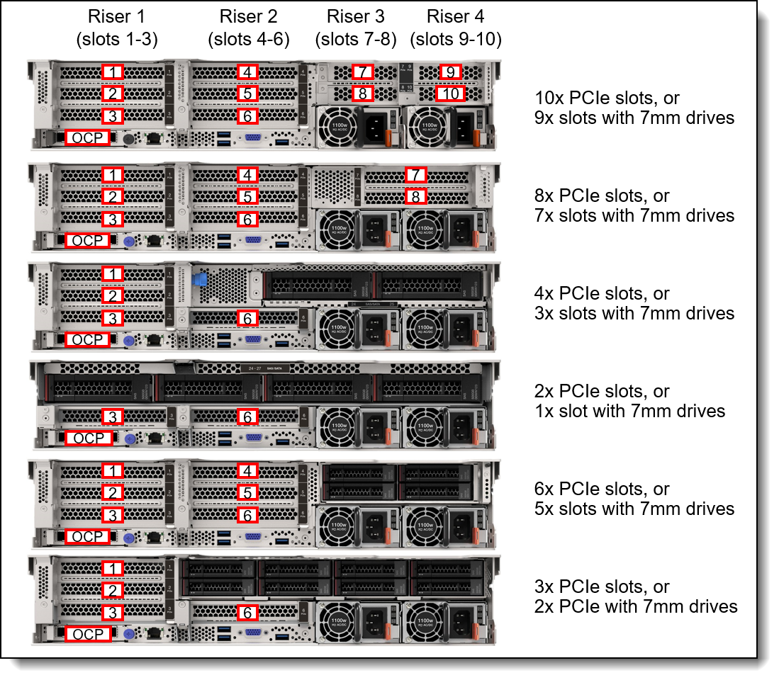
Figure 16. SR665 V3 rear slot configurations
The following figure shows the locations of the front-accessible slots.
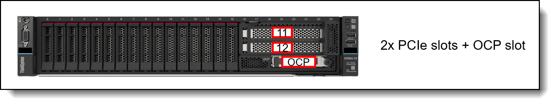
Figure 17. SR665 V3 front slots
Slot combinations
The SR665 V3 supports the riser combinations as listed in the following table. The table lists the PCIe slot risers in the rear of the server, the PCIe slots in the front of the server, and the front & rear OCP slots.
The table also lists the total number of PCIe slots (excluding the OCP slot) assuming a 3-slot riser is selected for Riser 1 and Riser 2.
| Total PCIe slots | Riser 1 | Riser 2 | Riser 3 | Riser 4 | Front slots | Rear OCP | Front OCP |
|---|---|---|---|---|---|---|---|
| Rear slots + Rear OCP | |||||||
| 3 | Yes | No | No | No | No | Yes | No |
| 6 | Yes | Yes | No | No | No | Yes | No |
| 8 | Yes | Yes | Yes | No | No | Yes | No |
| 10 | Yes | Yes | Yes | Yes | No | Yes | No |
| Rear + Front slots + Rear OCP | |||||||
| 5 | Yes | No | No | No | Yes | Yes | No |
| 8 | Yes | Yes | No | No | Yes | Yes | No |
| 10 | Yes | Yes | Yes | No | Yes | Yes | No |
| 12 | Yes | Yes | Yes | Yes | Yes | Yes | No |
| Rear + Front slots + Front OCP | |||||||
| 5 | Yes | No | No | No | Yes | No | Yes |
| 8 | Yes | Yes | No | No | Yes | No | Yes |
| Front slots + Rear OCP | |||||||
| 2 | No | No | No | No | Yes | Yes | No |
Slot ordering information
The following table lists the riser cards available for CTO builds and for field upgrades.
No slots: It is also possible to build a configuration without any slots, in which case slot fillers will be derived in the configurator. Slots can be added later as field upgrades using option part numbers as listed in the table.
| Part number |
Feature code |
Description | Slot configuration* (Green = Gen5, Blue = Gen4) |
Purpose | |||
|---|---|---|---|---|---|---|---|
| Rear Riser 1 (FH slots) | Slot 1 | Slot 2 | Slot 3 | ||||
| 4XH7A82898 | BPQU | ThinkSystem V3 2U x16/x8/x8 PCIe Gen5 Riser 1 or 2 | Gen5 x16 | Gen5 x8 | Gen5 x8 | 3 slots PCIe 5.0 | |
| 4XH7A82896 | BLKL | ThinkSystem V3 2U x16/x8/x8 PCIe Gen4 Riser1 or 2 | Gen4 x16 | Gen4 x8 | Gen4 x8 | 3 slots PCIe 4.0 | |
| 4XH7A82900 | BPQV | ThinkSystem V3 2U x16/x16/E PCIe Gen5 Riser1 or 2 | Gen5 x16 | Gen5 x16 | No slot | 2 slots PCIe 5.0; COM port or 7mm drives in slot 3 | |
| 4XH7A82892 | BLKM | ThinkSystem V3 2U x16/x16/E PCIe Gen4 Riser1 or 2 | Gen4 x16 | Gen4 x16 | No slot | 2 slots PCIe 4.0; COM port or 7mm drives in slot 3 | |
| 4XH7A82902 | BPQW | ThinkSystem V3 2U E/x16/x16 PCIe Gen5 Riser1 or 2 | No slot | Gen5 x16 | Gen4 x16 | PCIe 5.0 in slot 2; DW GPU in slot 2 | |
| 4XH7A82894 | BLKN | ThinkSystem V3 2U G4 E/x16/x16 PCIe Riser1 or 2 | No slot | Gen4 x16 | Gen4 x16 | 2 slots PCIe 4.0; DW GPU in slot 2 | |
| 4XH7A82890 | BLKP | ThinkSystem V3 2U x16 PCIe Gen4 Riser1 or 2 | No slot | No slot | Gen4 x16 | 1 slot PCIe 4.0; For 4x 3.5-inch rear drives | |
| Rear Riser 2 (FH slots) | Slot 4 | Slot 5 | Slot 6 | ||||
| 4XH7A82898 | BPQU | ThinkSystem V3 2U x16/x8/x8 PCIe Gen5 Riser 1 or 2 | Gen5 x16 | Gen5 x8 | Gen5 x8 | 3 slots PCIe 5.0 | |
| 4XH7A82896 | BLKL | ThinkSystem V3 2U x16/x8/x8 PCIe Gen4 Riser1 or 2 | Gen4 x16 | Gen4 x8 | Gen4 x8 | 3 slots PCIe 4.0 | |
| 4XH7A82900 | BPQV | ThinkSystem V3 2U x16/x16/E PCIe Gen5 Riser1 or 2 | Gen5 x16 | Gen5 x16 | No slot | 2 slots PCIe 5.0; COM port or 7mm drives in slot 6 | |
| 4XH7A82892 | BLKM | ThinkSystem V3 2U x16/x16/E PCIe Gen4 Riser1 or 2 | Gen4 x16 | Gen4 x16 | No slot | 2 slots PCIe 4.0; COM port or 7mm drives in slot 6 | |
| 4XH7A82902 | BPQW | ThinkSystem V3 2U E/x16/x16 PCIe Gen5 Riser1 or 2 | No slot | Gen5 x16 | Gen4 x16 | PCIe 5.0 in slot 5; DW GPU in slot 5 | |
| 4XH7A82894 | BLKN | ThinkSystem V3 2U G4 E/x16/x16 PCIe Riser1 or 2 | No slot | Gen4 x16 | Gen4 x16 | 2 slots PCIe 4.0; DW GPU in slot 5 | |
| 4XH7A82890 | BLKP | ThinkSystem V3 2U x16 PCIe Gen4 Riser1 or 2 | No slot | No slot | Gen4 x16 | 1 slot PCIe 4.0; For 2x or 4x 3.5-inch rear drives | |
| Rear Riser 3 (2x FH slots) | Slot 7 | Slot 8 | |||||
| 4XH7A85887 | BLL9 | ThinkSystem V3 2U x16/x16 PCIe Gen5 Riser3 Kit | Gen5 x16 | Gen5 x16 | 2x PCIe 5.0 x16 slots; DW GPU in slot 7 | ||
| 4XH7A85885 | BPKG | ThinkSystem V3 2U x16/x16 PCIe Gen4 Riser3 Kit with Cage | Gen4 x16 | Gen4 x16 | 2x PCIe 4.0 x16 slots; DW GPU in slot 7 | ||
| 4XH7A85886 | BPKH | ThinkSystem V3 2U x8/x8 PCIe Gen5 Riser3 Kit with Cage | Gen5 x8 | Gen5 x8 | 2x PCIe 5.0 x8 slots | ||
| 4XH7A85884 | BPKF | ThinkSystem V3 2U x8/x8 PCIe Gen4 Riser3 Kit with Cage | Gen4 x8 | Gen4 x8 | 2x PCIe 4.0 x8 slots | ||
| Rear Riser 3 & 4 (4x LP slots) | Slot 7 | Slot 8 | Slot 9 | Slot 10 | |||
| 4XH7A85888 | BQ2W† | ThinkSystem V3 2U PCIe Gen5 Riser 3/4-part 1 for Rear 10 slots | Gen5 x8 | Gen5 x8 | 2x PCIe 5.0 x8 slots | ||
| BTMS† | ThinkSystem V3 2U PCIe Gen5 Riser 3/4-part 2 for Rear 10 slots | Gen5 x8 | Gen4 x8 | 2x PCIe x8 slots (Gen 5, Gen4) | |||
| Front Riser | Slot 11 | Slot 12 | |||||
| 4XH7A85889 | BQ2X | ThinkSystem V3 2U Front x16/x16 PCIe G4 Riser | Gen4 x16 | Gen4 x16 | 2x PCIe 4.0 x16 front-accessible slots | ||
* All PCIe x8 slots are open ended and will physically support x16 adapters
† In the configurator, when feature BQ2W is selected, BTMS is automatically derived and provides slots 9 & 10. 4XH7A85888 contains both risers.
To configure the rear OCP slot, no additional feature codes are needed. To configure the front OCP slot, you will need the components listed in the following table. These components are used to route the rear OCP signals to the front of the server.
Tip: See the Slot combinations section to see which slot combinations are supported with the front and rear OCP slots
| Feature code | Description |
|---|---|
| BQ2E | ThinkSystem V3 1U/2U Front OCP Interposer Card |
| BQ2F* | ThinkSystem V3 1U/2U Rear OCP Interposer Card |
* BQ2F is automatically derived when BQ2E is selected
Configuration rules:
- Riser 3 is not supported with the M.2 adapter
- Front PCIe slots are not supported with the M.2 adapter
- For best performance, install PCIe 5.0 adapters in PCIe 5.0 (Gen5) slots
- The server only supports one OCP slot, either in the rear of the server or the front of the server, not both
- If you want to configure 4x low profile slots for slots 7-10, select feature BQ2W which provides riser 3 (slots 7, 8). Feature BTMS will then be automatically derived to provide riser 4 (slots 9 & 10), along with the necessary cables. Option part number 4XH7A85888 contains both of these risers and the cables.
- If you want to add both a 7mm drive enclosure plus 2x PCIe slots above it, you will need to order the 7mm drive option (either 4XH7A85898 or 4XH7A85899) plus the x16/x16/E riser kit (4XH7A82900 for PCIe Gen 5 or 4XH7A82892 for Gen 4). The riser kit part number provides the 2-slot riser card.
- All PCIe x8 slots are open ended and will physically support x16 adapters
Serial port
The SR665 V3 optionally supports a RS-232 serial port by adding a COM port bracket to either slot 3 or slot 6. Ordering information is shown in the following table.
Front PCIe slots: The serial port is not supported in the front PCIe slots
| Part number | Feature code | Description |
|---|---|---|
| 4X97A82921 | BMNJ | ThinkSystem V2/V3 1U COM Port Upgrade Kit |
The bracket is shown in the following figure. The option part number includes both Low Profile and Full Height brackets.
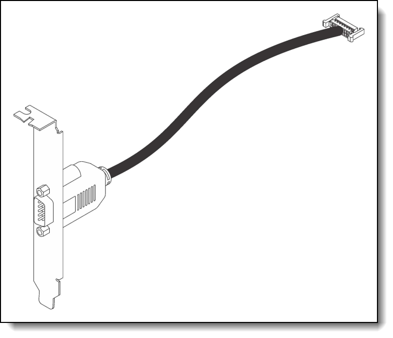
Figure 18. ThinkSystem V2/V3 1U COM Port Upgrade Kit
Network adapters
The server has a dedicated OCP 3.0 SFF slot with PCIe 5.0 x16 host interface. See Figure 3 for the location of the OCP slot.
The following table lists the supported OCP adapters. One port can optionally be shared with the XCC management processor for Wake-on-LAN and NC-SI support. Only 1 OCP card can be installed in the server, either rear-accessible or front-accessible.
| Part number |
Feature code |
Description | Maximum supported |
Windows 10/11 support |
|---|---|---|---|---|
| Gigabit Ethernet | ||||
| 4XC7A08235 | B5T1 | ThinkSystem Broadcom 5719 1GbE RJ45 4-port OCP Ethernet Adapter | 1 | Supported |
| 4XC7A08277 | B93E | ThinkSystem Intel I350 1GbE RJ45 4-port OCP Ethernet Adapter | 1 | Supported |
| 10 Gb Ethernet - 10GBASE-T | ||||
| 4XC7A08236 | B5ST | ThinkSystem Broadcom 57416 10GBASE-T 2-port OCP Ethernet Adapter | 1 | Supported |
| 4XC7A08240 | B5T4 | ThinkSystem Broadcom 57454 10GBASE-T 4-port OCP Ethernet Adapter | 1 | Supported |
| 4XC7A08278 | BCD5 | ThinkSystem Intel X710-T2L 10GBASE-T 2-port OCP Ethernet Adapter | 1 | Supported |
| 4XC7A80268 | BPPY | ThinkSystem Intel X710-T4L 10GBase-T 4-Port OCP Ethernet Adapter | 1 | Supported |
| 25 Gb Ethernet | ||||
| 4XC7A08237 | BN2T | ThinkSystem Broadcom 57414 10/25GbE SFP28 2-Port OCP Ethernet Adapter | 1 | Supported |
| 4XC7A80567 | BPPW | ThinkSystem Broadcom 57504 10/25GbE SFP28 4-Port OCP Ethernet Adapter | 1 | Supported |
| 4XC7A08294 | BCD4 | ThinkSystem Intel E810-DA2 10/25GbE SFP28 2-Port OCP Ethernet Adapter | 1 | Supported |
| 4XC7A80269 | BP8L | ThinkSystem Intel E810-DA4 10/25GbE SFP28 4-Port OCP Ethernet Adapter | 1 | Supported |
| 4XC7A62582 | BE4T | ThinkSystem Mellanox ConnectX-6 Lx 10/25GbE SFP28 2-Port OCP Ethernet Adapter | 1 | No |
| 100 Gb Ethernet | ||||
| 4XC7A08243 | BPPX | ThinkSystem Broadcom 57508 100GbE QSFP56 2-Port OCP Ethernet Adapter | 1 | Supported |
The following table lists additional supported network adapters that can be installed in the regular PCIe slots.
| Part number | Feature | Description | PCIe lanes |
Max Qty |
Slots supported |
Windows 10/11 support |
|||||
|---|---|---|---|---|---|---|---|---|---|---|---|
| Gigabit Ethernet | |||||||||||
| 7ZT7A00484 | AUZV | ThinkSystem Broadcom 5719 1GbE RJ45 4-Port PCIe Ethernet Adapter | Gen2 x4 | 10 | 1-12 | Supported | |||||
| 7ZT7A00535 | AUZW | ThinkSystem I350-T4 PCIe 1Gb 4-Port RJ45 Ethernet Adapter | Gen2 x4 | 10 | 1-12 | Supported | |||||
| 10 Gb Ethernet - 10GBASE-T | |||||||||||
| 7ZT7A00496 | AUKP | ThinkSystem Broadcom 57416 10GBASE-T 2-Port PCIe Ethernet Adapter | Gen3 x8 | 10 | 1-8,11,12 | Supported | |||||
| 4XC7A08245 | B5SU | ThinkSystem Broadcom 57454 10GBASE-T 4-port PCIe Ethernet Adapter | Gen3 x8 | 10 | 1-8,11,12 | Supported | |||||
| 4XC7A80266 | BNWL | ThinkSystem Intel X710-T2L 10GBase-T 2-Port PCIe Ethernet Adapter | Gen3 x8 | 10 | 1-12 | Supported | |||||
| 4XC7A79699 | BMXB | ThinkSystem Intel X710-T4L 10GBase-T 4-Port PCIe Ethernet Adapter | Gen3 x8 | 10 | 1-12 | Supported | |||||
| 25 Gb Ethernet | |||||||||||
| 4XC7A84827 | BUQK | ThinkSystem AMD X3522 10/25GbE DSFP28 2-Port PCIe Ethernet Adapter (Low Latency) | Gen4 x8 | 8 | 1-8,11,12* | No | |||||
| 4XC7A08238 | BK1H | ThinkSystem Broadcom 57414 10/25GbE SFP28 2-port PCIe Ethernet Adapter | Gen3 x8 | 10 | 1-12 | Supported | |||||
| 4XC7A80566 | BNWM | ThinkSystem Broadcom 57504 10/25GbE SFP28 4-Port PCIe Ethernet Adapter | Gen4 x16 | 6 | 1-8,11,12 | Supported | |||||
| 4XC7A08295 | BCD6 | ThinkSystem Intel E810-DA2 10/25GbE SFP28 2-Port PCIe Ethernet Adapter | Gen4 x8 | 10 | 1-12 | Supported | |||||
| 4XC7A80267 | BP8M | ThinkSystem Intel E810-DA4 10/25GbE SFP28 4-Port PCIe Ethernet Adapter | Gen4 x16 | 6 | 1-8,11,12 | Supported | |||||
| 4XC7A62580 | BE4U | ThinkSystem Mellanox ConnectX-6 Lx 10/25GbE SFP28 2-Port PCIe Ethernet Adapter | Gen4 x8 | 10 | 1-12 | No | |||||
| 4XC7A62581 | BHE2 | ThinkSystem Solarflare X2522-Plus 10/25GbE SFP28 2-Port PCIe Ethernet Adapter | Gen4 x8 | 10 | 1-12 | Supported | |||||
| 100 Gb Ethernet / HDR100 InfiniBand | |||||||||||
| 4XC7A08297 | BK1J | ThinkSystem Broadcom 57508 100GbE QSFP56 2-port PCIe 4 Ethernet Adapter | Gen4 x16 | 6 | 1,2,4,5, 7,8,11,12 | Supported | |||||
| 4XC7A08248 | B8PP | ThinkSystem Mellanox ConnectX-6 Dx 100GbE QSFP56 2-port PCIe Ethernet Adapter | Gen4 x16 | 6 | 1,2,4,5, 7,8,11,12 | No | |||||
| 4C57A14177 | B4R9 | ThinkSystem Mellanox ConnectX-6 HDR100/100GbE QSFP56 1-port PCIe VPI Adapter | Gen4 x16 | 6 | 1,2,4,5, 7,8,11,12 | No | |||||
| 4C57A14178 | B4RA | ThinkSystem Mellanox ConnectX-6 HDR100/100GbE QSFP56 2-port PCIe VPI Adapter | Gen4 x16 | 6 | 1,2,4,5, 7,8,11,12 | No | |||||
| 200 Gb Ethernet / HDR InfiniBand | |||||||||||
| 4C57A15326 | B4RC | ThinkSystem Mellanox ConnectX-6 HDR/200GbE QSFP56 1-port PCIe 4 VPI Adapter | Gen4 x16 | 6 | 1,2,4,5, 7,8,11,12 | No | |||||
| 4XC7A81883 | BQBN | ThinkSystem NVIDIA ConnectX-7 NDR200/HDR QSFP112 2-Port PCIe Gen5 x16 InfiniBand Adapter | Gen5 x16 | 6 | 1,2,4,5,7,8 | No | |||||
| 400 Gb Ethernet / NDR InfiniBand | |||||||||||
| 4XC7A80289 | BQ1N | ThinkSystem NVIDIA ConnectX-7 NDR400 OSFP 1-Port PCIe Gen5 Adapter | Gen5 x16 | 6 | 1,2,4,5,7,8 | No | |||||
* The AMD X3522 10/25GbE adapter is not supported in slot 2 or slot 3 of a x16/x8/x8 riser (BLKL or BPQU)
For more information, including the transceivers and cables that each adapter supports, see the list of Lenovo Press Product Guides in the Networking adapters category:
https://lenovopress.com/servers/options/ethernet
Configuration requirements:
- Adapters with a x16 host interface require a x16 slot to maximize performance
- PCIe Gen5 adapters will require a Gen5 riser to maximize performance
- E810 Ethernet and X350 RAID/HBAs: The use of both an Intel E810 network adapter and an X350 HBA/RAID adapter (9350, 5350 and 4350) is currently not supported in ThinkSystem servers. For details see Support Tip HT513226. Planned support for this combination of adapters is 2Q/2024.
Fibre Channel host bus adapters
The following table lists the Fibre Channel HBAs supported by the SR665 V3.
No Windows 10/11 support: None of the adapters listed in the table are supported with Windows 10 or Windows 11.
| Part number |
Feature code |
Description | PCIe lanes | Max qty |
Slots supported |
|---|---|---|---|---|---|
| 64 Gb Fibre Channel HBAs | |||||
| 4XC7A77485 | BLC1 | ThinkSystem Emulex LPe36002 64Gb 2-port PCIe Fibre Channel Adapter | Gen4 x8 | 10 | 1-12 |
| 32 Gb Fibre Channel HBAs | |||||
| 4XC7A76498 | BJ3G | ThinkSystem Emulex LPe35000 32Gb 1-port PCIe Fibre Channel Adapter v2 | Gen4 x8 | 10 | 1-12 |
| 4XC7A76525 | BJ3H | ThinkSystem Emulex LPe35002 32Gb 2-port PCIe Fibre Channel Adapter v2 | Gen4 x8 | 10 | 1-12 |
| 4XC7A08279 | BA1G | ThinkSystem QLogic QLE2770 32Gb 1-Port PCIe Fibre Channel Adapter | Gen4 x8 | 10 | 1-12 |
| 4XC7A08276 | BA1F | ThinkSystem QLogic QLE2772 32Gb 2-Port PCIe Fibre Channel Adapter | Gen4 x8 | 10 | 1-12 |
| 16 Gb Fibre Channel HBAs | |||||
| 01CV840 | ATZV | Emulex 16Gb Gen6 FC Dual-port HBA | Gen3 x8 | 10 | 1-12 |
| 01CV830 | ATZU | Emulex 16Gb Gen6 FC Single-port HBA | Gen3 x8 | 10 | 1-12 |
| 01CV760 | ATZC | QLogic 16Gb Enhanced Gen5 FC Dual-port HBA | Gen3 x8 | 10 | 1-12 |
| 01CV750 | ATZB | QLogic 16Gb Enhanced Gen5 FC Single-port HBA | Gen3 x8 | 10 | 1-12 |
For more information, see the list of Lenovo Press Product Guides in the Host bus adapters category:
https://lenovopress.com/servers/options/hba
SAS adapters for external storage
The following table lists SAS HBAs and RAID adapters supported by SR665 V3 server for use with external storage.
No Windows 10/11 support: None of the adapters listed in the table are supported with Windows 10 or Windows 11.
| Part number |
Feature code |
Description | PCIe lanes |
Max qty |
Slots supported |
|
|---|---|---|---|---|---|---|
| SAS HBAs | ||||||
| 4Y37A78837 | BNWK | ThinkSystem 440-8e SAS/SATA PCIe Gen4 12Gb HBA | Gen4 x8 | 8 | 1 - 8,11,12** | |
| 4Y37A09724 | B8P7 | ThinkSystem 440-16e SAS/SATA PCIe Gen4 12Gb HBA | Gen4 x8 | 8 | 1 - 8,11,12** | |
| External RAID adapters | ||||||
| 4Y37A78836 | BNWJ | ThinkSystem RAID 940-8e 4GB Flash PCIe Gen4 12Gb Adapter | Gen4 x8 | 4 | 1 - 8,11,12** | |
* See below regarding supercap requirements
** When Riser 3 is full-height slots, slots 1-8 are supported; when Riser 3 is configured as low-profile slots, 8 & 10 are supported, but 7 & 9 are not.
For a comparison of the functions of the supported storage adapters, see the ThinkSystem RAID Adapter and HBA Reference:
https://lenovopress.lenovo.com/lp1288#sr665-v3-support=SR665%2520V3&internal-or-external-ports=External
The RAID 940-8e adapter uses a flash power module (supercap), which can be installed in one of up to 4 locations in the server depending on the server configuration. See the RAID flash power module (supercap) support section for details. The number of 940-8e RAID adapters supported is based on how many supercaps can be installed in the server. If an internal RAID adapter with flash power modules is installed, the maximum number of 940-8e adapters supported is reduced by 1.
For more information, see the list of Lenovo Press Product Guides in the Host bus adapters and RAID adapters categories:
https://lenovopress.com/servers/options/hba
https://lenovopress.com/servers/options/raid
Flash storage adapters
The SR665 V3 currently does not support PCIe Flash Storage adapters.
GPU adapters
This section describes the supported GPUs.
GPU part numbers
The SR665 V3 supports the following graphics processing units (GPUs).
| Part number |
Feature code |
Description | TDP | Aux power |
PCIe lanes |
Max qty |
Slots supported |
Windows 10/11 support |
|---|---|---|---|---|---|---|---|---|
| Double-wide GPUs | ||||||||
| 4X67A90669 | BYFH | ThinkSystem NVIDIA L40S 48GB PCIe Gen4 Passive GPU | 350W | Yes | Gen4 x16 | 3 | 2, 5, 7 | Supported |
| 4X67A84823 | BT87 | ThinkSystem NVIDIA L40 48GB PCIe Gen4 Passive GPU | 300W | Yes | Gen4 x16 | 3 | 2, 5, 7 | Supported |
| 4X67A81102 | BP04 | ThinkSystem AMD Instinct MI210 PCIe Gen4 Passive Accelerator | 300W | Yes | Gen4 x16 | 3 | 2, 5, 7 | No |
| 4X67A82257 | BR9U | ThinkSystem NVIDIA H100 80GB PCIe Gen5 Passive GPU | 350W | Yes | Gen5 x16 | 3 | 2, 5, 7 | No |
| 4X67A76715 | BLK1 | ThinkSystem NVIDIA A100 80GB PCIe Gen4 Passive GPU | 300W | Yes | Gen4 x16 | 3 | 2, 5, 7 | No |
| CTO only | BQZP | ThinkSystem NVIDIA A100 80GB PCIe Gen4 Passive GPU w/o CEC | 300W | Yes | Gen4 x16 | 3 | 2, 5, 7 | No |
| 4X67A72593 | BQZQ | ThinkSystem NVIDIA A40 48GB PCIe Gen4 Passive GPU w/o CEC | 300W | Yes | Gen4 x16 | 3 | 2, 5, 7 | Supported |
| 4X67A76581 | BJHG | ThinkSystem NVIDIA A30 24GB PCIe Gen4 Passive GPU | 165W | Yes | Gen4 x16 | 3 | 2, 5, 7 | Supported |
| CTO only | BQZR | ThinkSystem NVIDIA A30 24GB PCIe Gen4 Passive GPU w/o CEC | 165W | Yes | Gen4 x16 | 3 | 2, 5, 7 | Supported |
| 4X67A76727 | BQZU | ThinkSystem NVIDIA A16 64GB Gen4 PCIe Passive GPU w/o CEC | 250W | Yes | Gen4 x16 | 3 | 2, 5, 7 | Supported |
| 4X67A71310 | BFT0 | ThinkSystem NVIDIA RTX A6000 48GB PCIe Active GPU | 300W | Yes | Gen4 x16 | 3 | 2, 5, 7 | Supported |
| 4X67A76726 | BNFD | ThinkSystem NVIDIA RTX A4500 20GB PCIe Active GPU | 200W | Yes | Gen4 x16 | 3 | 2, 5, 7 | Supported |
| 4X67A76720 | BMT9 | ThinkSystem NVIDIA RTX A2000 12GB PCIe Active GPU | 70W | Yes | Gen4 x16 | 3 | 2, 5, 7 | Supported |
| Single-wide GPUs | ||||||||
| 4X67A81547 | BP05 | ThinkSystem NVIDIA A2 16GB PCIe Gen4 Passive GPU | 60W | No | Gen4 x8 | 8 | 1 - 8 | Supported |
| CTO only | BQZT | ThinkSystem NVIDIA A2 16GB PCIe Gen4 Passive GPU w/o CEC | 60W | No | Gen4 x8 | 8 | 1 - 8 | Supported |
* When a double-wide GPU is installed in slot 2, 5 or 7, the adjacent slot 1, 4 and 8 respectively is not available
For information about these GPUs, see the ThinkSystem GPU Summary, available at:
https://lenovopress.com/lp0768-thinksystem-thinkagile-gpu-summary
For CTO orders, the SR665 V3 also supports the selection of a placeholder for a GPU. This selection results in a "GPU ready" configuration which ensures that the server ships with the components needed for GPU installation (GPU power cables, air ducts, power supplies, fans, etc) without actually including the GPUs themselves. The following table lists the ordering information for CTO orders.
| Part number | Feature code | Description |
|---|---|---|
| CTO only | BW40 | ThinkSystem NVIDIA A4500 GPU-Ready Installation |
| CTO only | BVLL | ThinkSystem NVIDIA H100 GPU-Ready Installation |
| CTO only | BW3Z | ThinkSystem NVIDIA L40 GPU-Ready Installation |
| CTO only | BZUS | ThinkSystem NVIDIA L40S GPU-Ready Installation |
| CTO only | BP4X | ThinkSystem DW GPU-Ready Installation (for all other supported DW GPUs) |
Configuration rules
The following configuration requirements must be met when installing GPUs:
- Some NVIDIA A Series GPUs are available as two feature codes, one with a CEC chip and one without a CEC chip (ones without the CEC chip have "w/o CEC" in the name). The CEC is a secondary Hardware Root of Trust (RoT) module that provides an additional layer of security, which can be used by customers who have high regulatory requirements or high security standards. NVIDIA uses a multi-layered security model and hence the protection offered by the primary Root of Trust embedded in the GPU is expected to be sufficient for most customers. The CEC defeatured products still offer Secure Boot, Secure Firmware Update, Firmware Rollback Protection, and In-Band Firmware Update Disable. Specifically, without the CEC chip, the GPU does not support Key Revocation or Firmware Attestation. CEC and non-CEC GPUs of the same type of GPU can be mixed in field upgrades.
- All GPUs installed must be identical
- When a double-wide GPU is installed in slot 2, 5 or 7, the adjacent slot 1, 4 and 8 respectively is not available
- Flash storage adapters are not supported.
- Middle drive bays and Rear drive bays are not supported
- For details regarding supported combinations of front drive bays, processors, fans, and ambient temperature, see the Thermal Rules page of the User Guide:
https://pubs.lenovo.com/sr665-v3/thermal_rules#gpu-configurations
Riser selections for double-wide GPUs
When a double-wide GPU is installed in slot 2, 5 or 7, the adjacent slot 1, 4 and 8 respectively is not available. The riser cards listed in the following table are used with double-wide GPUs.
| Riser | Part number | Feature code | Description |
|---|---|---|---|
| Riser 1 (GPU in slot 2) - PCIe Gen5 | 4XH7A82902 | BPQW | ThinkSystem V3 2U E/x16/x16 PCIe Gen5 Riser1 or 2 |
| Riser 1 (GPU in slot 2) - PCIe Gen4 | 4XH7A82894 | BLKN | ThinkSystem V3 2U G4 E/x16/x16 PCIe Riser1 or 2 |
| Riser 2 (GPU in slot 5) - PCIe Gen5 | 4XH7A82902 | BPQW | ThinkSystem V3 2U E/x16/x16 PCIe Gen5 Riser1 or 2 |
| Riser 2 (GPU in slot 5) - PCIe Gen4 | 4XH7A82894 | BLKN | ThinkSystem V3 2U G4 E/x16/x16 PCIe Riser1 or 2 |
| Riser 3 (GPU in slot 7) - PCIe Gen5 | 4XH7A85887 | BLL9 | ThinkSystem V3 2U x16/x16 PCIe Gen5 Riser3 Kit |
| Riser 3 (GPU in slot 7) - PCIe Gen4 | 4XH7A85885 | BPKG | ThinkSystem V3 2U x16/x16 PCIe Gen4 Riser3 Kit with Cage |
GPU Enablement Kit
When installing any full-length GPU as a field upgrade, you will also need to order the GPU Enablement Kit as listed in the following table. This kit is not required for the NVIDIA A2 GPU.
| Part number | Description | Maximum supported |
|---|---|---|
| 4X67A85856 | ThinkSystem SR665 V3 GPU Full Length Thermal Option Kit
|
1 |
The following figure shows the GPU air duct with GPU air duct fillers and GPU extend air ducts installed. Note that the drawings might not 100% reflect the shipping components.
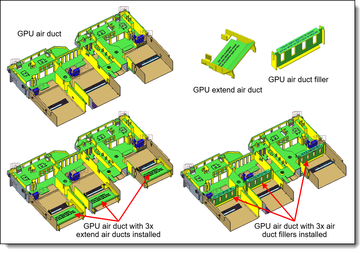
Figure 19. SR665 V3 GPU air duct
GPU cable kits
The following cable kits are offered to provide auxiliary power cables for GPUs that require one. See the Supported GPUs table to see which GPUs require an auxiliary power cable.
Configuration notes:
- This cable kits are only required for field upgrades; factory (CTO) orders will automatically include any required cables.
- For double-wide GPUs, The DW (double-wide) cable kit is only required if you are adding additional double-wide GPUs to a server that already has a DW GPU installed from a CTO order. If you are doing a field upgrade to install the first DW GPU to a server, order the ThinkSystem SR665 V3 GPU Full Length Thermal Option Kit, 4X67A85856 instead, since the Enablement Kit includes the necessary power cables.
- The SW (single-wide) cable kit is required if you are doing any field upgrades to add a single-wide GPU that requires an auxiliary power cable (GPU power > 75 W), however, all currently supported GPUs do not require auxiliary power cables.
| Part number | Description |
|---|---|
| 4X97A86165 |
ThinkSystem SR665 V3/SR655 V3 DW GPU Cable Option Kit
|
| 4X97A86166 |
ThinkSystem SR665 V3/SR655 V3 SW GPU Cable Option Kit
|
Cooling
The SR665 V3 server has up to six 60 mm hot-swap variable-speed fans. Five fans are needed when one processor is installed and six fans are required when two processors are installed. The server offers N+1 redundancy. The server also has one or two additional fans integrated in each of the two power supplies.
Depending on the configuration, the server will need either Standard fans (single-rotor 17K RPM) or Performance fans (dual-rotor 21K RPM).
Under all of the following conditions, standard fans can be used:
- CPUs have a TDP < 240W
- No GPUs
- No Mellanox ConnectX-6 or ConnectX-7 adapters
- No Broadcom 57454 10GBASE-T 4-port OCP adapter
- No 3DS RDIMMs
- No front 12x 3.5-inch drive bays
- No mid-chassis drive bays
- No rear drive bays
If any conditions are not met, Performance fans are required.
Ordering information for the fans is listed in the following table.
| Part number | Feature code |
Description | Quantity required |
|---|---|---|---|
| 4F17A14497 | BH8F | ThinkSystem V3 2U Standard Fan Option Kit | 1x CPU: 5 2x CPUs: 6 |
| 4F17A82884 | BLL6 | ThinkSystem V3 2U Performance Fan Option Kit | 1x CPU: 5 2x CPUs: 6 |
Power supplies
The SR665 V3 supports up to two redundant hot-swap power supplies.
The power supply choices are listed in the following table. Both power supplies used in server must be identical.
Tip: When configuring a server in the DCSC configurator, power consumption is calculated precisely by interfacing with Lenovo Capacity Planner. You can therefore select the appropriate power supply for your configuration. However, do consider future upgrades that may require additional power needs.
| Part number | Feature code |
Description | Connector | Max quantity |
110V AC | 220V AC | 240V DC PRC only |
-48V DC |
|---|---|---|---|---|---|---|---|---|
| AC input power - 80 PLUS Titanium efficiency | ||||||||
| 4P57A82019 | BR1X | ThinkSystem 750W 230V Titanium Hot-Swap Gen2 Power Supply v3 | C13 | 2 | No | Yes | Yes | No |
| CTO only | C07V | ThinkSystem 750W 230V Titanium Hot-Swap Gen2 Power Supply v4 | C13 | 2 | No | Yes | Yes | No |
| 4P57A72666 | BLKH | ThinkSystem 1100W 230V Titanium Hot-Swap Gen2 Power Supply | C13 | 2 | No | Yes | Yes | No |
| 4P57A78359 | BPK9 | ThinkSystem 1800W 230V Titanium Hot-Swap Gen2 Power Supply | C13 | 2 | No | Yes | Yes | No |
| 4P57A72667 | BKTJ | ThinkSystem 2600W 230V Titanium Hot-Swap Gen2 Power Supply | C19 | 2 | No | Yes | Yes | No |
| AC input power - 80 PLUS Platinum efficiency | ||||||||
| 4P57A72670 | BNFG | ThinkSystem 750W 230V/115V Platinum Hot-Swap Gen2 Power Supply v3 | C13 | 2 | Yes | Yes | Yes | No |
| 4P57A72671 | BNFH | ThinkSystem 1100W 230V/115V Platinum Hot-Swap Gen2 Power Supply v3 | C13 | 2 | Yes | Yes | Yes | No |
| 4P57A26294
|
BMUF | ThinkSystem 1800W 230V Platinum Hot-Swap Gen2 Power Supply v2 | C13 | 2 | No | Yes | Yes | No |
| 4P57A26295 | B962 | ThinkSystem 2400W 230V Platinum Hot-Swap Gen2 Power Supply | C19 | 2 | No | Yes | Yes | No |
| -48V DC input power | ||||||||
| 4P57A26296 | B8QE | ThinkSystem 1100W -48V DC Hot-Swap Gen2 Power Supply | DC | 2 | No | No | No | Yes |
Supported power supplies are auto-sensing dual-voltage units, supporting both 110V AC (100-127V 50/60 Hz) and 220V AC (200-240V 50/60 Hz) power. For China customers, all power supplies support 240V DC.
AC power supplies up to 1800W have a C14 connector. AC power supplies 2400W and above have a C19 connector.
The supported -48V DC power supply has a Weidmuller TOP 4GS/3 7.6 terminal as shown in the following figure.
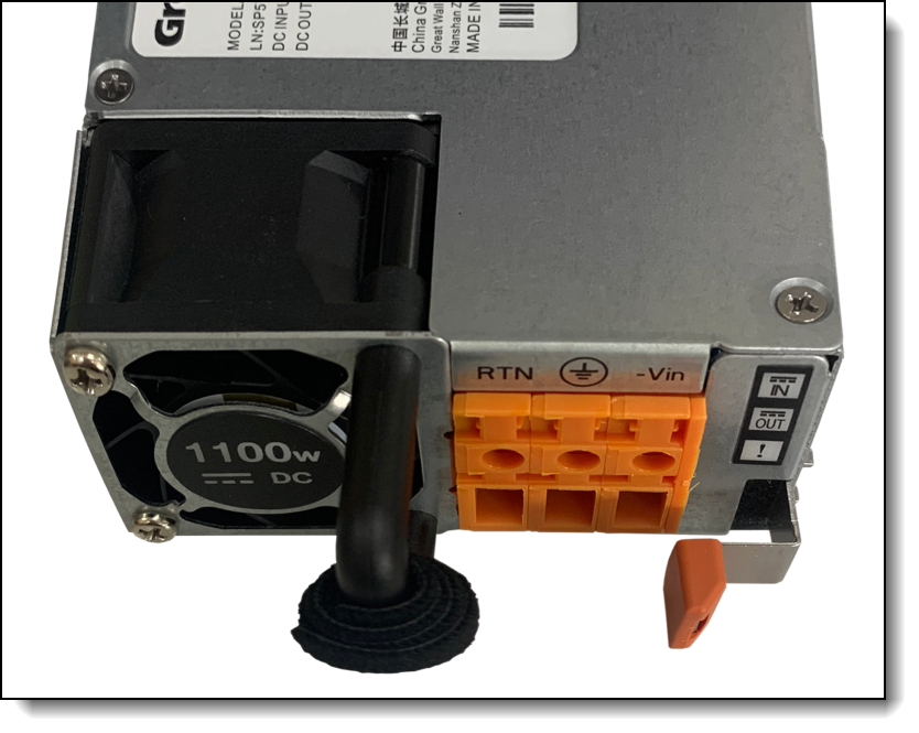
Figure 20. Connector on the ThinkSystem 1100W -48V DC Hot-Swap Gen2 Power Supply
Power supply options do not include a line cord. For server configurations, the inclusion of a power cord is model dependent. Configure-to-order models can be configured without power cords if desired.
Power supply LEDs
The supported hot-swap power supplies have the following LEDs:
- Power input LED:
- Green: The power supply is connected to the AC power source
- Off: The power supply is disconnected from the AC power source or a power problem has occurred
- Power output LED:
- Green: The server is on and the power supply is working normally
- Blinking green: The power supply is in Zero-output/Standby mode (see below)
- Off: The server is powered off, or the power supply is not working properly
- Power supply error LED:
- Off: The power supply is working normally
- Yellow: The power supply has failed
Zero-output mode: When Zero-output mode (also known as Standby mode or Cold Redundancy mode) is configured in XCC and the server power load is sufficiently low, one of the installed power supplies enters into the Standby state while the other one delivers entire load. When the power load increases, the standby power supply will switch to Active state to provide sufficient power to the server. Zero-output mode can be enabled or disabled in the XClarity Controller web interface, Server Configuration > Power Policy. If you select Disable, then both power supplies will be in the Active state.
Power cords
Line cords and rack power cables with C13 connectors can be ordered as listed in the following table.
110V customers: If you plan to use the 1100W power supply with a 110V power source, select a power cable that is rated above 10A. Power cables that are rated at 10A or below are not supported with 110V power.
| Part number | Feature code | Description |
|---|---|---|
| Rack cables - C13 to C14 | ||
| SL67B08593 | BPHZ | 0.5m, 10A/100-250V, C13 to C14 Jumper Cord |
| 00Y3043 | A4VP | 1.0m, 10A/100-250V, C13 to IEC 320-C14 Rack Power Cable |
| 4L67A08367 | B0N5 | 1.0m, 13A/100-250V, C13 to C14 Jumper Cord |
| 39Y7937 | 6201 | 1.5m, 10A/100-250V, C13 to IEC 320-C14 Rack Power Cable |
| 4L67A08368 | B0N6 | 1.5m, 13A/100-250V, C13 to C14 Jumper Cord |
| 4L67A08365 | B0N4 | 2.0m, 10A/100-250V, C13 to IEC 320-C14 Rack Power Cable |
| 4L67A08369 | 6570 | 2.0m, 13A/100-250V, C13 to C14 Jumper Cord |
| 4L67A08366 | 6311 | 2.8m, 10A/100-250V, C13 to IEC 320-C14 Rack Power Cable |
| 4L67A08370 | 6400 | 2.8m, 13A/100-250V, C13 to C14 Jumper Cord |
| 39Y7932 | 6263 | 4.3m, 10A/100-250V, C13 to IEC 320-C14 Rack Power Cable |
| 4L67A08371 | 6583 | 4.3m, 13A/100-250V, C13 to C14 Rack Power Cable |
| Rack cables - C13 to C14 (Y-cable) | ||
| 00Y3046 | A4VQ | 1.345m, 2X C13 to C14 Jumper Cord, Rack Power Cable |
| 00Y3047 | A4VR | 2.054m, 2X C13 to C14 Jumper Cord, Rack Power Cable |
| Rack cables - C13 to C20 | ||
| 39Y7938 | 6204 | 2.8m, 10A/100-250V, C13 to IEC 320-C20 Rack Power Cable |
| Rack cables - C13 to C20 (Y-cable) | ||
| 47C2491 | A3SW | 1.2m, 16A/100-250V, 2 Short C13s to Short C20 Rack Power Cable |
| 47C2492 | A3SX | 2.5m, 16A/100-250V, 2 Long C13s to Short C20 Rack Power Cable |
| 47C2493 | A3SY | 2.8m, 16A/100-250V, 2 Short C13s to Long C20 Rack Power Cable |
| 47C2494 | A3SZ | 4.1m, 16A/100-250V, 2 Long C13s to Long C20 Rack Power Cable |
| Line cords | ||
| 39Y7930 | 6222 | 2.8m, 10A/250V, C13 to IRAM 2073 (Argentina) Line Cord |
| 81Y2384 | 6492 | 4.3m 10A/220V, C13 to IRAM 2073 (Argentina) Line Cord |
| 39Y7924 | 6211 | 2.8m, 10A/250V, C13 to AS/NZ 3112 (Australia/NZ) Line Cord |
| 81Y2383 | 6574 | 4.3m, 10A/230V, C13 to AS/NZS 3112 (Aus/NZ) Line Cord |
| 69Y1988 | 6532 | 2.8m, 10A/250V, C13 to NBR 14136 (Brazil) Line Cord |
| 81Y2387 | 6404 | 4.3m, 10A/250V, C13 - 2P+Gnd (Brazil) Line Cord |
| 39Y7928 | 6210 | 2.8m, 220-240V, C13 to GB 2099.1 (China) Line Cord |
| 81Y2378 | 6580 | 4.3m, 10A/220V, C13 to GB 2099.1 (China) Line Cord |
| 39Y7918 | 6213 | 2.8m, 10A/250V, C13 to DK2-5a (Denmark) Line Cord |
| 81Y2382 | 6575 | 4.3m, 10A/230V, C13 to DK2-5a (Denmark) Line Cord |
| 39Y7917 | 6212 | 2.8m, 10A/230V, C13 to CEE7-VII (Europe) Line Cord |
| 81Y2376 | 6572 | 4.3m, 10A/230V, C13 to CEE7-VII (Europe) Line Cord |
| 39Y7927 | 6269 | 2.8m, 10A/250V, C13(2P+Gnd) (India) Line Cord |
| 81Y2386 | 6567 | 4.3m, 10A/240V, C13 to IS 6538 (India) Line Cord |
| 39Y7920 | 6218 | 2.8m, 10A/250V, C13 to SI 32 (Israel) Line Cord |
| 81Y2381 | 6579 | 4.3m, 10A/230V, C13 to SI 32 (Israel) Line Cord |
| 39Y7921 | 6217 | 2.8m, 220-240V, C13 to CEI 23-16 (Italy/Chile) Line Cord |
| 81Y2380 | 6493 | 4.3m, 10A/230V, C13 to CEI 23-16 (Italy/Chile) Line Cord |
| 46M2593 | A1RE | 2.8m, 12A/125V, C13 to JIS C-8303 (Japan) Line Cord |
| 4L67A08362 | 6495 | 4.3m, 12A/200V, C13 to JIS C-8303 (Japan) Line Cord |
| 39Y7926 | 6335 | 4.3m, 12A/100V, C13 to JIS C-8303 (Japan) Line Cord |
| 39Y7922 | 6214 | 2.8m, 10A/250V, C13 to SABS 164 (S Africa) Line Cord |
| 81Y2379 | 6576 | 4.3m, 10A/230V, C13 to SABS 164 (South Africa) Line Cord |
| 39Y7925 | 6219 | 2.8m, 220-240V, C13 to KETI (S Korea) Line Cord |
| 81Y2385 | 6494 | 4.3m, 12A/220V, C13 to KSC 8305 (S. Korea) Line Cord |
| 39Y7919 | 6216 | 2.8m, 10A/250V, C13 to SEV 1011-S24507 (Swiss) Line Cord |
| 81Y2390 | 6578 | 4.3m, 10A/230V, C13 to SEV 1011-S24507 (Sws) Line Cord |
| 23R7158 | 6386 | 2.8m, 10A/125V, C13 to CNS 10917-3 (Taiwan) Line Cord |
| 81Y2375 | 6317 | 2.8m, 10A/240V, C13 to CNS 10917-3 (Taiwan) Line Cord |
| 81Y2374 | 6402 | 2.8m, 13A/125V, C13 to CNS 60799 (Taiwan) Line Cord |
| 4L67A08363 | AX8B | 4.3m, 10A 125V, C13 to CNS 10917 (Taiwan) Line Cord |
| 81Y2389 | 6531 | 4.3m, 10A/250V, C13 to 76 CNS 10917-3 (Taiwan) Line Cord |
| 81Y2388 | 6530 | 4.3m, 13A/125V, C13 to CNS 10917 (Taiwan) Line Cord |
| 39Y7923 | 6215 | 2.8m, 10A/250V, C13 to BS 1363/A (UK) Line Cord |
| 81Y2377 | 6577 | 4.3m, 10A/230V, C13 to BS 1363/A (UK) Line Cord |
| 90Y3016 | 6313 | 2.8m, 10A/120V, C13 to NEMA 5-15P (US) Line Cord |
| 46M2592 | A1RF | 2.8m, 10A/250V, C13 to NEMA 6-15P Line Cord |
| 00WH545 | 6401 | 2.8m, 13A/120V, C13 to NEMA 5-15P (US) Line Cord |
| 4L67A08359 | 6370 | 4.3m, 10A/125V, C13 to NEMA 5-15P (US) Line Cord |
| 4L67A08361 | 6373 | 4.3m, 10A/250V, C13 to NEMA 6-15P (US) Line Cord |
| 4L67A08360 | AX8A | 4.3m, 13A/120V, C13 to NEMA 5-15P (US) Line Cord |
Power cords (C19 connectors)
Line cords and rack power cables with C19 connectors can be ordered as listed in the following table.
| Part number | Feature code | Description |
|---|---|---|
| Rack cables | ||
| 4L67A86677 | BPJ0 | 0.5m, 16A/100-250V, C19 to IEC 320-C20 Rack Power Cable |
| 4L67A86678 | B4L0 | 1.0m, 16A/100-250V, C19 to IEC 320-C20 Rack Power Cable |
| 4L67A86679 | B4L1 | 1.5m, 16A/100-250V, C19 to IEC 320-C20 Rack Power Cable |
| 4L67A86680 | B4L2 | 2.0m, 16A/100-250V, C19 to IEC 320-C20 Rack Power Cable |
| 39Y7916 | 6252 | 2.5m, 16A/100-240V, C19 to IEC 320-C20 Rack Power Cable |
| 4L67A86681 | B4L3 | 4.3m, 16A/100-250V, C19 to IEC 320-C20 Rack Power Cable |
| Line cords | ||
| 40K9777 | 6276 | 4.3m, 220-240V, C19 to IRAM 2073 (Argentina) Line cord |
| 40K9773 | 6284 | 4.3m, 220-240V, C19 to AS/NZS 3112 (Aus/NZ) Line cord |
| 40K9775 | 6277 | 4.3m, 250V, C19 to NBR 14136 (Brazil) Line Cord |
| 40K9774 | 6288 | 4.3m, 220-240V, C19 to GB2099.1 (China) Line cord |
| 40K9769 | 6283 | 4.3m, 16A/230V, C19 to IEC 309-P+N+G (Den/Sws) Line Cord |
| 40K9766 | 6279 | 4.3m, 220-240V, C19 to CEE7-VII (European) Line cord |
| 40K9776 | 6285 | 4.3m, 220-240V, C19 to IS6538 (India) Line cord |
| 40K9771 | 6282 | 4.3m, 220-240V, C19 to SI 32 (Israel) Line cord |
| 40K9768 | 6281 | 4.3m, 220-240V, C19 to CEI 23-16 (Italy) Line cord |
| 40K9770 | 6280 | 4.3m, 220-240V, C19 to SABS 164 (South Africa) Line cord |
| 41Y9231 | 6289 | 4.3m, 15A/250V, C19 to KSC 8305 (S. Korea) Line Cord |
| 81Y2391 | 6549 | 4.3m, 16A/230V, C19 to SEV 1011 (Sws) Line Cord |
| 41Y9230 | 6287 | 4.3m, 16A/250V, C19 to CNS 10917-3 (Taiwan) Line Cord |
| 40K9767 | 6278 | 4.3m, 220-240V, C19 to BS 1363/A w/13A fuse (UK) Line Cord |
| 40K9772 | 6275 | 4.3m, 16A/208V, C19 to NEMA L6-20P (US) Line Cord |
| 00D7197 | A1NV | 4.3m, 15A/250V, C19 to NEMA 6-15P (US) Line Cord |
Systems management
The SR665 V3 contains an integrated service processor, XClarity Controller 2 (XCC), which provides advanced control, monitoring, and alerting functions. The XCC2 is based on the AST2600 baseboard management controller (BMC) using a dual-core ARM Cortex A7 32-bit RISC service processor running at 1.2 GHz.
Topics in this section:
System I/O Board
The SR665 V3 implements a separate System I/O Board that connects to the Processor Board. The location of the System I/O Board is shown in the Components and connectors section. The System I/O Board contains all the connectors visible at the rear of the server as shown in the following figure.
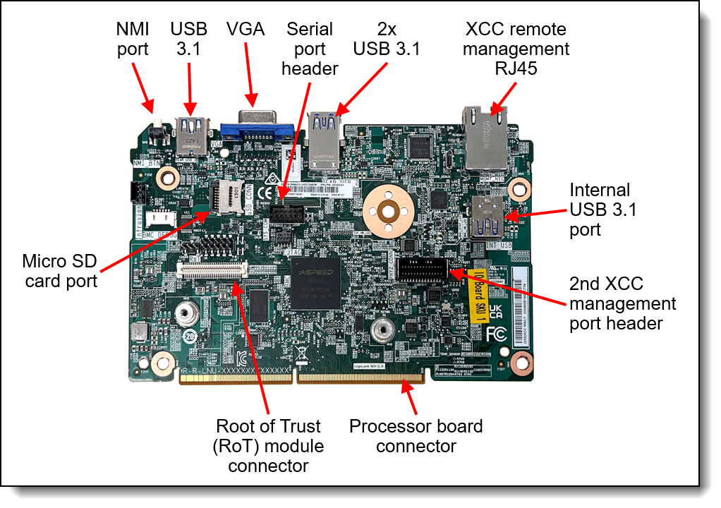
Figure 21. System I/O Board
The board also has the following components:
- XClarity Controller 2, implemented using the ASPEED AST2600 baseboard management controller (BMC).
- Root of Trust (RoT) module - a daughter card that implements Platform Firmware Resiliency (PFR) hardware Root of Trust (RoT) which enables the server to be NIST SP800-193 compliant. For more details about PFR, see the Security section.
- Connector to enable an additional redundant Ethernet connection to the XCC2 controller. The connector is used in conjunction with the ThinkSystem V3 Management NIC Adapter Kit (4XC7A85319). For details, see the Remote management section.
- Internal USB port - to allow the booting of an operating system from a USB key. The VMware ESXi preloads use this port for example. Preloads are described in the Operating system support section.
- MicroSD card port to enable the use of a MicroSD card for additional storage for use with the XCC2 controller. XCC2 can use the storage as a Remote Disc on Card (RDOC) device (up to 4GB of storage). It can also be used to store firmware updates (including N-1 firmware history) for ease of deployment.
Tip: Without a MicroSD card installed, the XCC2 controller will have 100MB of available RDOC storage.
Ordering information for the supported USB drive and Micro SD card are listed in the following table.
| Part number | Feature code | Description |
|---|---|---|
| 4X77A77065 | BNWN | ThinkSystem USB 32GB USB 3.0 Flash Drive |
| 4X77A77064 | BNWP | ThinkSystem MicroSD 32GB Class 10 Flash Memory Card |
Local management
The SR665 V3 offers a front operator panel with key LED status indicators, as shown in the following figure.
Tip: The Network LED only shows network activity of the installed OCP network adapter.
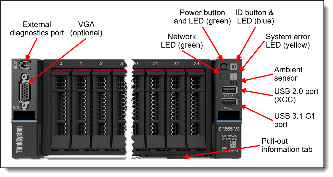
Figure 22. Front operator controls are on the left and right side of the server
Light path diagnostics
The server offers light path diagnostics. If an environmental condition exceeds a threshold or if a system component fails, XCC lights LEDs inside the server to help you diagnose the problem and find the failing part. The server has fault LEDs next to the following components:
- Each memory DIMM
- Each drive bay
- Each power supply
Front VGA and External Diagnostics ports
The VGA port at the rear of the server is included in all models, however the VGA port at the front of the server is optional. Also optional is the External Diagnostics port which enables the use of the External Diagnostics Handset.
To configure either the VGA port or the External Diagnostics port at the front of the server, select one of the following feature codes when configuring the server.
| Part number | Feature code | Description | Front VGA port |
External diagnostics port |
|---|---|---|---|---|
| CTO only | BQQ2 | ThinkSystem 2U V3 EIA Latch Standard | No | No |
| 4XH7A86164 | BQQ1 | ThinkSystem 2U V3 EIA Latch with VGA & External Diagnostics Ports | Included | Included |
| 4XH7A86816 | BQQ4 | ThinkSystem 2U V3 EIA Latch with External Diagnostics Port | No | Included |
| 4XH7A86817 | BQQ3 | ThinkSystem 2U V3 EIA Latch with VGA Port | Included | No |
External Diagnostics Handset
The SR665 V3 optionally has a port to connect an External Diagnostics Handset as described in the preceding section. The External Diagnostics Handset has the same functions as the Integrated Diagnostics Panel but has the advantages of not consuming space on the front of the server plus it can be shared among many servers in your data center. The handset has a magnet on the back of it to allow you to easily mount it on a convenient place on any rack cabinet.
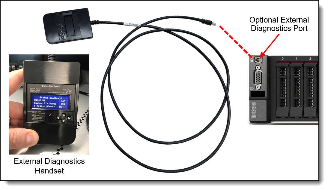
Figure 23. External Diagnostics Handset
Ordering information for the External Diagnostics Handset with is listed in the following table.
| Part number | Feature code | Description |
|---|---|---|
| 4TA7A64874 | BEUX | ThinkSystem External Diagnostics Handset |
Integrated Diagnostics Panel for 8x 2.5-inch and 16x 2.5-inch drive bay configurations
For configurations with 8x 2.5-inch or 16x 2.5-inch drive bays at the front, the server can optionally be configured to have a pull-out Integrated Diagnostics Panel. The following figure shows the standard (fixed) operator panel and the optional Integrated Diagnostics Panel.
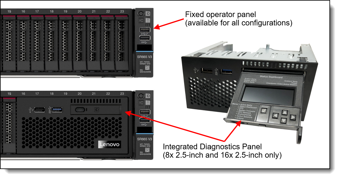
Figure 24. Operator panel choices for the 8x 2.5-inch drive bay configuration
The Integrated Diagnostics Panel allows quick access to system status, firmware, network, and health information. The LCD display on the panel and the function buttons give you access to the following information:
- Active alerts
- Status Dashboard
- System VPD: machine type & mode, serial number, UUID string
- System firmware levels: UEFI and XCC firmware
- XCC network information: hostname, MAC address, IP address, DNS addresses
- Environmental data: Ambient temperature, CPU temperature, AC input voltage, estimated power consumption
- Active XCC sessions
- System reset action
The Integrated Diagnostics Panel can be configured as listed in the following table. It is only available configure-to-order (CTO); not available as a field upgrade.
| Part number | Feature code | Description |
|---|---|---|
| CTO only | BMJA | ThinkSystem 2U 16x2.5" Front Operator Panel v2 |
Information pull-out tab
The front of the server also houses an information pull-out tab (also known as the network access tag). See Figure 2 for the location. A label on the tab shows the network information (MAC address and other data) to remotely access the service processor.
System status with XClarity Mobile
The XClarity Mobile app includes a tethering function where you can connect your Android or iOS device to the server via USB to see the status of the server.
The steps to connect the mobile device are as follows:
- Enable USB Management on the server, by holding down the ID button for 3 seconds (or pressing the dedicated USB management button if one is present)
- Connect the mobile device via a USB cable to the server's USB port with the management symbol

- In iOS or Android settings, enable Personal Hotspot or USB Tethering
- Launch the Lenovo XClarity Mobile app
Once connected you can see the following information:
- Server status including error logs (read only, no login required)
- Server management functions (XClarity login credentials required)
Remote management
The server offers a dedicated RJ45 port at the rear of the server for remote management via the XClarity Controller management processor. The port supports 10/100/1000 Mbps speeds.
Remote server management is provided through industry-standard interfaces:
- Intelligent Platform Management Interface (IPMI) Version 2.0
- Simple Network Management Protocol (SNMP) Version 3 (no SET commands; no SNMP v1)
- Common Information Model (CIM-XML)
- Representational State Transfer (REST) support
- Redfish support (DMTF compliant)
- Web browser - HTML 5-based browser interface (Java and ActiveX not required) using a responsive design (content optimized for device being used - laptop, tablet, phone) with NLS support
The SR665 V3 also supports the use of an OCP adapter that provides an additional redundant Ethernet connection to the XCC2 controller. Ordering information is listed in the following table.
| Part number |
Feature code |
Description | Maximum quantity |
|---|---|---|---|
| 4XC7A85319 | BTMQ | ThinkSystem V3 Management NIC Adapter Kit | 1 |
The use of this adapter allows concurrent remote access using both the connection on the adapter and the onboard RJ45 remote management port provided by the server. The adapter and onboard port have separate IP addresses.
Configuration rules:
- The Redundant System Management Port Adapter is installed in the OCP adapter slot at the rear of the server and is mutually exclusive with any OCP network adapter.
- It is not supported installed in the front OCP slot (if the front OCP slot is configured)
- If the Redundant System Management Port Adapter is installed in the rear slot, then the front OCP slot (if configured) cannot be used.
The following figure shows the server with the Redundant System Management Port Adapter installed in the OCP slot.
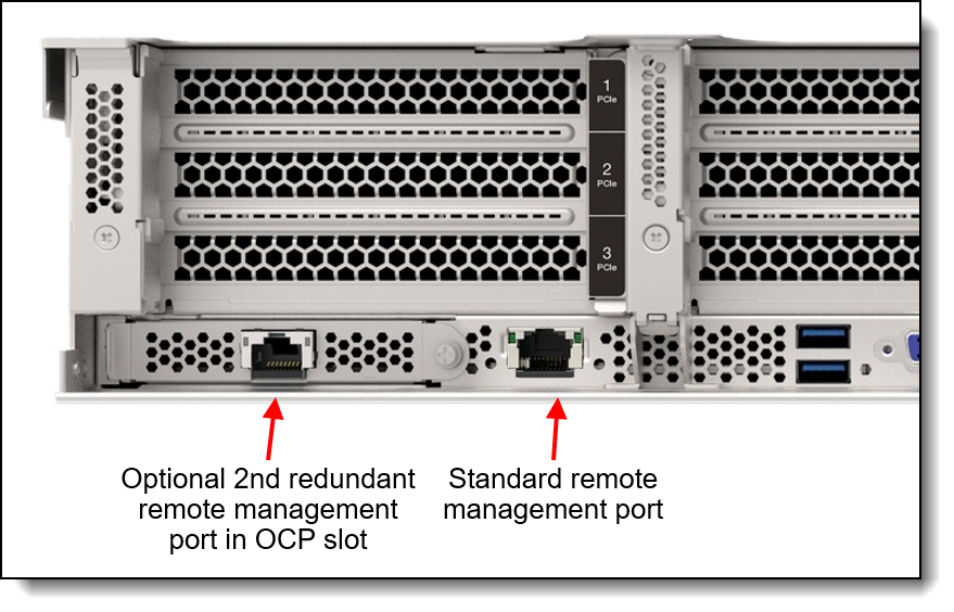
Figure 25. SR665 V3 with the Redundant System Management Port Adapter installed
IPMI via the Ethernet port (IPMI over LAN) is supported, however it is disabled by default. For CTO orders you can specify whether you want to the feature enabled or disabled in the factory, using the feature codes listed in the following table.
| Feature code | Description |
|---|---|
| B7XZ | Disable IPMI-over-LAN (default) |
| B7Y0 | Enable IPMI-over-LAN |
XCC2 Platinum
The XCC2 service processor in the SR665 V3 supports an upgrade to the Platinum level of features. Compared to the XCC functions of ThinkSystem V2 and earlier systems, Platinum adds the same features as Enterprise and Advanced levels in ThinkSystem V2, plus additional features.
XCC2 Platinum adds the following Enterprise and Advanced functions:
- Remotely viewing video with graphics resolutions up to 1600x1200 at 75 Hz with up to 23 bits per pixel, regardless of the system state
- Remotely accessing the server using the keyboard and mouse from a remote client
- International keyboard mapping support
- Syslog alerting
- Redirecting serial console via SSH
- Component replacement log (Maintenance History log)
- Access restriction (IP address blocking)
- Lenovo SED security key management
- Displaying graphics for real-time and historical power usage data and temperature
- Boot video capture and crash video capture
- Virtual console collaboration - Ability for up to 6 remote users to be log into the remote session simultaneously
- Remote console Java client
- Mapping the ISO and image files located on the local client as virtual drives for use by the server
- Mounting the remote ISO and image files via HTTPS, SFTP, CIFS, and NFS
- System utilization data and graphic view
- Single sign on with Lenovo XClarity Administrator
- Update firmware from a repository
- License for XClarity Energy Manager
Note: The SR665 V3 does not support Power capping.
XCC2 Platinum also adds the following features that are new to XCC2:
- System Guard - Monitor hardware inventory for unexpected component changes, and simply log the event or prevent booting
- Enterprise Strict Security mode - Enforces CNSA 1.0 level security
- Neighbor Group - Enables administrators to manage and synchronize configurations and firmware level across multiple servers
Ordering information is listed in the following table. XCC2 Platinum is a software license upgrade - no additional hardware is required.
| Part number | Feature code | Description |
|---|---|---|
| 7S0X000DWW | S91X | Lenovo XClarity XCC2 Platinum Upgrade |
| 7S0X000KWW | SBCV | Lenovo XClarity Controller 2 (XCC2) Platinum Upgrade |
With XCC2 Platinum, for CTO orders, you can request that System Guard be enabled in the factory and the first configuration snapshot be recorded. To add this to an order, select feature code listed in the following table. The selection is made in the Security tab of the DCSC configurator.
| Feature code | Description |
|---|---|
| BUT2 | Install System Guard |
For more information about System Guard, see https://pubs.lenovo.com/xcc2/NN1ia_c_systemguard
Lenovo XClarity Provisioning Manager
Lenovo XClarity Provisioning Manager (LXPM) is a UEFI-based application embedded in ThinkSystem servers and accessible via the F1 key during system boot.
LXPM provides the following functions:
- Graphical UEFI Setup
- System inventory information and VPD update
- System firmware updates (UEFI and XCC)
- RAID setup wizard
- OS installation wizard (including unattended OS installation)
- Diagnostics functions
Lenovo XClarity Administrator
Lenovo XClarity Administrator is a centralized resource management solution designed to reduce complexity, speed response, and enhance the availability of Lenovo systems and solutions. It provides agent-free hardware management for ThinkSystem servers, in addition to ThinkServer, System x, and Flex System servers. The administration dashboard is based on HTML 5 and allows fast location of resources so tasks can be run quickly.
Because Lenovo XClarity Administrator does not require any agent software to be installed on the managed endpoints, there are no CPU cycles spent on agent execution, and no memory is used, which means that up to 1GB of RAM and 1 - 2% CPU usage is saved, compared to a typical managed system where an agent is required.
Lenovo XClarity Administrator is an optional software component for the SR665 V3. The software can be downloaded and used at no charge to discover and monitor the SR665 V3 and to manage firmware upgrades.
If software support is required for Lenovo XClarity Administrator, or premium features such as configuration management and operating system deployment are required, Lenovo XClarity Pro software subscription should be ordered. Lenovo XClarity Pro is licensed on a per managed system basis, that is, each managed Lenovo system requires a license.
The following table lists the Lenovo XClarity software license options.
| Part number | Feature code | Description |
|---|---|---|
| 00MT201 | 1339 | Lenovo XClarity Pro, per Managed Endpoint w/1 Yr SW S&S |
| 00MT202 | 1340 | Lenovo XClarity Pro, per Managed Endpoint w/3 Yr SW S&S |
| 00MT203 | 1341 | Lenovo XClarity Pro, per Managed Endpoint w/5 Yr SW S&S |
| 7S0X000HWW | SAYV | Lenovo XClarity Pro, per Managed Endpoint w/6 Yr SW S&S |
| 7S0X000JWW | SAYW | Lenovo XClarity Pro, per Managed Endpoint w/7 Yr SW S&S |
Lenovo XClarity Administrator offers the following standard features that are available at no charge:
- Auto-discovery and monitoring of Lenovo systems
- Firmware updates and compliance enforcement
- External alerts and notifications via SNMP traps, syslog remote logging, and e-mail
- Secure connections to managed endpoints
- NIST 800-131A or FIPS 140-2 compliant cryptographic standards between the management solution and managed endpoints
- Integration into existing higher-level management systems such as cloud automation and orchestration tools through REST APIs, providing extensive external visibility and control over hardware resources
- An intuitive, easy-to-use GUI
- Scripting with Windows PowerShell, providing command-line visibility and control over hardware resources
Lenovo XClarity Administrator offers the following premium features that require an optional Pro license:
- Pattern-based configuration management that allows to define configurations once and apply repeatedly without errors when deploying new servers or redeploying existing servers without disrupting the fabric
- Bare-metal deployment of operating systems and hypervisors to streamline infrastructure provisioning
For more information, refer to the Lenovo XClarity Administrator Product Guide:
http://lenovopress.com/tips1200
Lenovo XClarity Integrators
Lenovo also offers software plug-in modules, Lenovo XClarity Integrators, to manage physical infrastructure from leading external virtualization management software tools including those from Microsoft and VMware.
These integrators are offered at no charge, however if software support is required, a Lenovo XClarity Pro software subscription license should be ordered.
Lenovo XClarity Integrators offer the following additional features:
- Ability to discover, manage, and monitor Lenovo server hardware from VMware vCenter or Microsoft System Center
- Deployment of firmware updates and configuration patterns to Lenovo x86 rack servers and Flex System from the virtualization management tool
- Non-disruptive server maintenance in clustered environments that reduces workload downtime by dynamically migrating workloads from affected hosts during rolling server updates or reboots
- Greater service level uptime and assurance in clustered environments during unplanned hardware events by dynamically triggering workload migration from impacted hosts when impending hardware failures are predicted
For more information about all the available Lenovo XClarity Integrators, see the Lenovo XClarity Administrator Product Guide: https://lenovopress.com/tips1200-lenovo-xclarity-administrator
Lenovo XClarity Essentials
Lenovo offers the following XClarity Essentials software tools that can help you set up, use, and maintain the server at no additional cost:
- Lenovo Essentials OneCLI
OneCLI is a collection of server management tools that uses a command line interface program to manage firmware, hardware, and operating systems. It provides functions to collect full system health information (including health status), configure system settings, and update system firmware and drivers.
- Lenovo Essentials UpdateXpress
The UpdateXpress tool is a standalone GUI application for firmware and device driver updates that enables you to maintain your server firmware and device drivers up-to-date and help you avoid unnecessary server outages. The tool acquires and deploys individual updates and UpdateXpress System Packs (UXSPs) which are integration-tested bundles.
- Lenovo Essentials Bootable Media Creator
The Bootable Media Creator (BOMC) tool is used to create bootable media for offline firmware update.
For more information and downloads, visit the Lenovo XClarity Essentials web page:
http://support.lenovo.com/us/en/documents/LNVO-center
Lenovo XClarity Energy Manager
Lenovo XClarity Energy Manager (LXEM) is a power and temperature management solution for data centers. It is an agent-free, web-based console that enables you to monitor and manage power consumption and temperature in your data center through the management console. It enables server density and data center capacity to be increased through the use of power capping.
LXEM is a licensed product. A single-node LXEM license is included with the XClarity Controller Platinum upgrade as described in the XCC2 Platinum section. If your server does not have the XCC Platinum upgrade, Energy Manager licenses can be ordered as shown in the following table.
| Part number | Description |
|---|---|
| 4L40E51621 | Lenovo XClarity Energy Manager Node License (1 license needed per server) |
Note: The SR665 V3 does not support the following Energy Manager functions:
- Power capping
- Policy-based management
For more information about XClarity Energy Manager, see the following resources:
- Lenovo Support page:
https://datacentersupport.lenovo.com/us/en/solutions/lnvo-lxem - User Guide for XClarity Energy Manager:
https://pubs.lenovo.com/lxem/
Lenovo Capacity Planner
Lenovo Capacity Planner is a power consumption evaluation tool that enhances data center planning by enabling IT administrators and pre-sales professionals to understand various power characteristics of racks, servers, and other devices. Capacity Planner can dynamically calculate the power consumption, current, British Thermal Unit (BTU), and volt-ampere (VA) rating at the rack level, improving the planning efficiency for large scale deployments.
For more information, refer to the Capacity Planner web page:
http://datacentersupport.lenovo.com/us/en/solutions/lnvo-lcp
Security
Topics in this section:
Security features
The SR665 V3 server offers the following electronic security features:
- Secure Boot function of the AMD EPYC processor
- Support for Platform Firmware Resiliency (PFR) hardware Root of Trust (RoT) - see the Platform Firmware Resiliency section
- Firmware signature processes compliant with FIPS and NIST requirements
- System Guard (part of XCC Platinum) - Proactive monitoring of hardware inventory for unexpected component changes
- Administrator and power-on password
- Integrated Trusted Platform Module (TPM) supporting TPM 2.0
- Self-encrypting drives (SEDs) with support for enterprise key managers - see the SED encryption key management section
The server is NIST SP 800-147B compliant.
The SR665 V3 server also offers the following physical security features:
- Optional chassis intrusion switch
- Optional lockable front security bezel
The optional lockable front security bezel is shown in the following figure and includes a key that enables you to secure the bezel over the drives and system controls thereby reducing the chance of unauthorized or accidental access to the server.
Front PCIe slots: The use of the security bezel is not supported when the server has front PCIe slots.
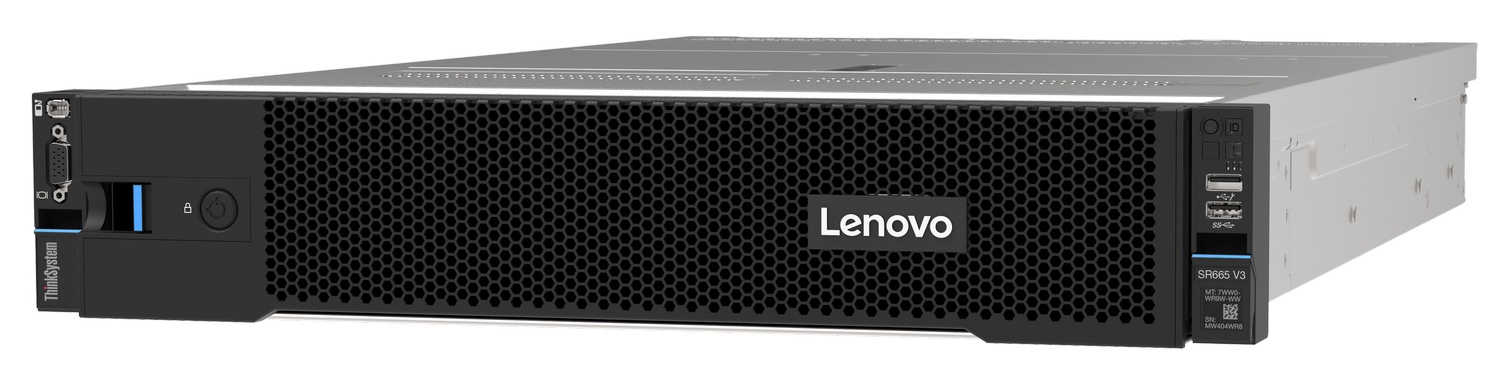
Figure 26. Lockable front security bezel
The dimensions of the security bezel are:
- Width: 437 mm (17.2 in.)
- Height: 87 mm (3.4 in.)
- Width: 23 mm (0.9 in.)
The following table lists the security options for the SR665 V3.
| Part number | Feature code | Description |
|---|---|---|
| 4X97A82927 | BAJJ | ThinkSystem SR650 V3/SR655 V3 Intrusion Cable |
| 4X97A90518 | BVGB | ThinkSystem SR665 V3 Intrusion Cable |
| 4XH7A09886 | B8M2 | ThinkSystem V2 2U Security Bezel Option Kit |
| 4XH7A90300 | BXBQ | ThinkSystem V3 2U Security Bezel Option Kit |
Tip: The only difference between security bezels 4XH7A09886 and 4XH7A90300 is the Lenovo logo: On 4XH7A09886, the logo is made from plastic; on 4XH7A90300, the logo is made from aluminum alloy.
Platform Firmware Resiliency - Lenovo ThinkShield
Lenovo's ThinkShield Security is a transparent and comprehensive approach to security that extends to all dimensions of our data center products: from development, to supply chain, and through the entire product lifecycle.
The ThinkSystem SR665 V3 includes Platform Firmware Resiliency (PFR) hardware Root of Trust (RoT) which enables the system to be NIST SP800-193 compliant. This offering further enhances key platform subsystem protections against unauthorized firmware updates and corruption, to restore firmware to an integral state, and to closely monitor firmware for possible compromise from cyber-attacks.
PFR operates upon the following server components:
- UEFI image – the low-level server firmware that connects the operating system to the server hardware
- XCC image – the management “engine” software that controls and reports on the server status separate from the server operating system
- FPGA image – the code that runs the server’s lowest level hardware controller on the motherboard
The Lenovo Platform Root of Trust Hardware performs the following three main functions:
- Detection – Measures the firmware and updates for authenticity
- Recovery – Recovers a corrupted image to a known-safe image
- Protection – Monitors the system to ensure the known-good firmware is not maliciously written
These enhanced protection capabilities are implemented using a dedicated, discrete security processor whose implementation has been rigorously validated by leading third-party security firms. Security evaluation results and design details are available for customer review – providing unprecedented transparency and assurance.
The SR665 V3 includes support for Secure Boot, a UEFI firmware security feature developed by the UEFI Consortium that ensures only immutable and signed software are loaded during the boot time. The use of Secure Boot helps prevent malicious code from being loaded and helps prevent attacks, such as the installation of rootkits. Lenovo offers the capability to enable secure boot in the factory, to ensure end-to-end protection. Alternatively, Secure Boot can be left disabled in the factory, allowing the customer to enable it themselves at a later point, if desired.
The following table lists the relevant feature code(s).
| Part number | Feature code | Description | Purpose |
|---|---|---|---|
| CTO only | BPKQ | TPM 2.0 with Secure Boot | Configure the system in the factory with Secure Boot enabled. |
| CTO only | BPKR | TPM 2.0 | Configure the system without Secure Boot enabled. Customers can enable Secure Boot later if desired. |
Tip: If Secure Boot is not enabled in the factory, it can be enabled later by the customer. However once Secure Boot is enabled, it cannot be disabled.
Security standards
The SR665 V3 supports the following security standards and capabilities:
- Industry Standard Security Capabilities
- AMD CPU Enablement
- AES-NI (Advanced Encryption Standard New Instructions)
- GMET (Guest Mode Execute Trap)
- Hardware-based side channel attack resilience enhancements
- NX (No eXecute)
- PSB (Platform Secure Boot)
- Shadow Stack
- SEV (Secure Encrypted Virtualization)
- SEV-ES (Encrypted State register encryption)
- SEV-SNP (Secure Nested Paging)
- SVM (Secure Virtual Machine)
- SME (Secure Memory Encryption)
- UMIP (User Mode Instruction Prevention)
- Microsoft Windows Security Enablement
- Credential Guard
- Device Guard
- Host Guardian Service
- TCG (Trusted Computing Group) TPM (Trusted Platform Module) 2.0
- UEFI (Unified Extensible Firmware Interface) Forum Secure Boot
- AMD CPU Enablement
- Hardware Root of Trust and Security
- Independent security subsystem providing platform-wide NIST SP800-193 compliant Platform Firmware Resilience (PFR)
- Host domain RoT supplemented by AMD Platform Secure Boot (PSB)
- Management domain RoT supplemented by the Secure Boot features of XCC
- Platform Security
- Boot and run-time firmware integrity monitoring with rollback to known-good firmware (e.g., “self-healing”)
- Non-volatile storage bus security monitoring and filtering
- Resilient firmware implementation, such as to detect and defeat unauthorized flash writes or SMM (System Management Mode) memory incursions
- Patented IPMI KCS channel privileged access authorization (USPTO Patent# 11,256,810)
- Host and management domain authorization, including integration with CyberArk for enterprise password management
- KMIP (Key Management Interoperability Protocol) compliant, including support for IBM SKLM and Thales KeySecure
- Reduced “out of box” attack surface
- Configurable network services
- FIPS 140-3 (in progress) validated cryptography for XCC
- CNSA Suite 1.0 Quantum-resistant cryptography for XCC
- Lenovo System Guard
For more information on platform security, see the paper “How to Harden the Security of your ThinkSystem Server and Management Applications” available from https://lenovopress.com/lp1260-how-to-harden-the-security-of-your-thinksystem-server.
- Standards Compliance and/or Support
- NIST SP800-131A rev 2 “Transitioning the Use of Cryptographic Algorithms and Key Lengths”
- NIST SP800-147B “BIOS Protection Guidelines for Servers”
- NIST SP800-193 “Platform Firmware Resiliency Guidelines”
- ISO/IEC 11889 “Trusted Platform Module Library”
- Common Criteria TCG Protection Profile for “PC Client Specific TPM 2.0”
- European Union Commission Regulation 2019/424 (“ErP Lot 9”) “Ecodesign Requirements for Servers and Data Storage Products” Secure Data Deletion
- Optional FIPS 140-2 validated Self-Encrypting Disks (SEDs) with external KMIP-based key management
- Product and Supply Chain Security
- Suppliers validated through Lenovo’s Trusted Supplier Program
- Developed in accordance with Lenovo’s Secure Development Lifecycle (LSDL)
- Continuous firmware security validation through automated testing, including static code analysis, dynamic network and web vulnerability testing, software composition analysis, and subsystem-specific testing, such as UEFI security configuration validation
- Ongoing security reviews by US-based security experts, with attestation letters available from our third-party security partners
- Digitally signed firmware, stored and built on US-based infrastructure and signed on US-based Hardware Security Modules (HSMs)
- TAA (Trade Agreements Act) compliant manufacturing, by default in Mexico for North American markets with additional US and EU manufacturing options
- US 2019 NDAA (National Defense Authorization Act) Section 889 compliant
Rack installation
The following table lists the rack installation options that are available for the SR665 V3.
| Part number | Feature | Description |
|---|---|---|
| Rail Kits | ||
| 4M17A13564 | BK7W | ThinkSystem Toolless Friction Rail v2 |
| 4M17A11754 | B8LA | ThinkSystem Toolless Slide Rail Kit v2 |
| 4M17A11756 | B91Y | ThinkSystem Toolless Slide Rail Kit v2 with 2U CMA |
| Enhanced Rail Kits for > 34 kg server weight* | ||
| 4M17A11755 | B8LB | ThinkSystem Toolless Slide Rail Kit v2 Enhanced |
| 4M17A11757 | B97N | ThinkSystem Toolless Slide Rail Kit v2 Enhanced with 2U CMA |
| Separate Cable Management Arm | ||
| 7M27A05698 | B135 | ThinkSystem 2U CMA Upgrade Kit for Toolless Slide Rail |
* The Enhanced Slide Rail Kits are used when the server is shipped in a rack and the server is 34 kg or heavier (configuration with 20x 3.5-inch HDDs for example)
The following table summarizes the rail kit features and specifications.
| Feature | ThinkSystem Toolless Friction Rail v2 | ThinkSystem Toolless Slide Rail Kit v2 | ThinkSystem Toolless Slide Rail Kit v2 Enhanced | ThinkSystem Toolless Slide Rail Kit v2 with 2U CMA | ThinkSystem Toolless Slide Rail Kit v2 Enhanced with 2U CMA |
|---|---|---|---|---|---|
| Option part number | 4M17A13564 | 4M17A11754 | 4M17A11755 | 4M17A11756 | 4M17A11757 |
| Rail type | Half-out slide rail (friction) | Full-out slide rail (ball bearing) | Full-out slide rail (ball bearing) | Full-out slide rail (ball bearing) | Full-out slide rail (ball bearing) |
| Toolless installation | Yes | Yes | Yes | Yes | Yes |
| CMA support | No | Optional, 7M27A05698* | Optional, 7M27A05698* | Included | Included |
| Supported rack type | Four-post IBM and Lenovo standard rack, complying with the IEC standard | Four-post IBM and Lenovo standard rack, complying with the IEC standard | Four-post IBM and Lenovo standard rack, complying with the IEC standard | Four-post IBM and Lenovo standard rack, complying with the IEC standard | Four-post IBM and Lenovo standard rack, complying with the IEC standard |
| In-rack server maintenance | No | Yes | Yes | Yes | Yes |
| 1U PDU support | Yes | Yes | Yes | Yes | Yes |
| 0U PDU support | Yes | Limited support** | Limited support** | Limited support** | Limited support** |
| Supported mounting holes | Square or round | Square or round | Square, round, or threaded | Square or round | Square, round, or threaded |
| Thickness of mounting flanges | 2.0-3.3 mm (0.08-0.13 inches) | 2.0-3.3 mm (0.08-0.13 inches) | 2.0-3.3 mm (0.08-0.13 inches) | 2.0-3.3 mm (0.08-0.13 inches) | 2.0-3.3 mm (0.08-0.13 inches) |
| Supported distance between front and rear mounting flanges‡ | 610-864 mm (24-34 inches) | 610-813 mm (24-32 inches) | 635-813 mm (25-32 inches) | 610-813 mm (24-32 inches) | 635-813 mm (25-32 inches) |
| Rail length† | 751 mm (29.6 inches) | 740 mm (29.1 inches) | 740 mm (29.1 inches) | 820 mm (32.3 inches) | 820 mm (32.3 inches) |
* CMA mounting brackets are not preinstalled on the rail. The CMA mounting brackets are contained in the CMA option kit package and you will need to install the CMA mounting brackets first. For detailed instructions, refer to the documentation that comes with the CMA option kit.
** If you want to install the rails and a 0U PDU into the same rack, the rack must meet the height and depth requirements as described in ThinkSystem Rail Support Matrix.
‡ For best performance, it is recommended that you install the rails to the racks with a 719-mm distance (28.31-inch, Lenovo rack default distance) between the front and rear mounting flanges.
† Measured when mounted on the rack, from the front surface of the front mounting flange to the rear most point of the rail. Rail is in closed position.
Operating system support
The SR665 V3 supports the following operating systems:
- Microsoft Windows 10 Professional (x64)
- Microsoft Windows 11 Professional (x64)
- Microsoft Windows Server 2019
- Microsoft Windows Server 2022
- Red Hat Enterprise Linux 8.6
- Red Hat Enterprise Linux 8.7
- Red Hat Enterprise Linux 8.8
- Red Hat Enterprise Linux 8.9
- Red Hat Enterprise Linux 9.0
- Red Hat Enterprise Linux 9.1
- Red Hat Enterprise Linux 9.2
- Red Hat Enterprise Linux 9.3
- SUSE Linux Enterprise Server 15 SP4
- SUSE Linux Enterprise Server 15 SP5
- SUSE Linux Enterprise Server 15 Xen SP4
- SUSE Linux Enterprise Server 15 Xen SP5
- Ubuntu 20.04 LTS 64-bit
- Ubuntu 22.04 LTS 64-bit
- VMware ESXi 7.0 U3
- VMware ESXi 8.0
- VMware ESXi 8.0 U1
- VMware ESXi 8.0 U2
For a complete list of supported, certified and tested operating systems, plus additional details and links to relevant web sites, see the Operating System Interoperability Guide: https://lenovopress.lenovo.com/osig#servers=sr665-v3-7d9b-7d9a
For configure-to-order configurations, the server can be preloaded with VMware ESXi installed on M.2 cards. Ordering information is listed in the following table.
| Part number | Feature code | Description |
|---|---|---|
| CTO only | BMEY | VMware ESXi 7.0 U3 (Factory Installed) |
| CTO only | BMT5 | VMware ESXi 8.0 (Factory Installed) |
| CTO only | BYC7 | VMware ESXi 8.0 U2 (Factory Installed) |
Configuration rule:
- An ESXi preload cannot be selected if the configuration includes an NVIDIA GPU (ESXi preload cannot include the NVIDIA driver)
You can download supported VMware vSphere hypervisor images from the following web page and load it on the M.2 drives or 7mm drives using the instructions provided:
Windows 10 and Windows 11
The SR665 V3 can now run Windows 10 and Windows 11, however only a subset of adapters and drives can be installed. For ease of configuration, additional Base CTO models 7D9ACTO2WW and 7D9BCTO2WW have been created to assist building a configuration that can be used with the client operating systems. See the Models section for details.
The XClarity management toolset is supported with Windows 10 and Windows 11.
Windows client license: A Windows client license for the system cannot be ordered from Lenovo nor can the OS be preloaded on the system in the factory. For the Windows license and for preloads, please contact your Lenovo business partner. A Windows Pro license is required as a qualifying base OS license in order to use a client Volume License offering.
See the part number tables in the following sections to see which adapters are supported with Windows 10 and Windows 11:
GPU recommended: Lenovo recommends that if you plan to install Windows 10 or 11 on this server to run graphics-intensive applications, then you should selected a dedicated graphics adapter (GPU).
The following components are not supported:
- Fibre Channel adapters
- InfiniBand and VPI adapters
- External storage adapters
- Flash storage adapters
Physical and electrical specifications
The SR665 V3 has the following overall physical dimensions, excluding components that extend outside the standard chassis, such as EIA flanges, front security bezel (if any), and power supply handles:
- Width: 445 mm (17.5 inches)
- Height: 87 mm (3.4 inches)
- Depth: 766 mm (30.1 inches)
The following table lists the detailed dimensions. See the figure below for the definition of each dimension.
| Dimension | Description |
|---|---|
| 482 mm | Xa = Width, to the outsides of the front EIA flanges |
| 435 mm | Xb = Width, to the rack rail mating surfaces |
| 445 mm | Xc = Width, to the outer most chassis body feature |
| 87 mm | Ya = Height, from the bottom of chassis to the top of the chassis |
| 698 mm | Za = Depth, from the rack flange mating surface to the rearmost I/O port surface |
| 732 mm | Zb = Depth, from the rack flange mating surface to the rearmost feature of the chassis body |
| 727 mm (≤1100W) 755 mm (1800W) 781 mm (2400W) |
Zc = Depth, from the rack flange mating surface to the rearmost feature such as power supply handle |
| 34 mm | Zd = Depth, from the forwardmost feature on front of EIA flange to the rack flange mating surface |
| 46 mm | Ze = Depth, from the front of security bezel (if applicable) or forwardmost feature to the rack flange mating surface |
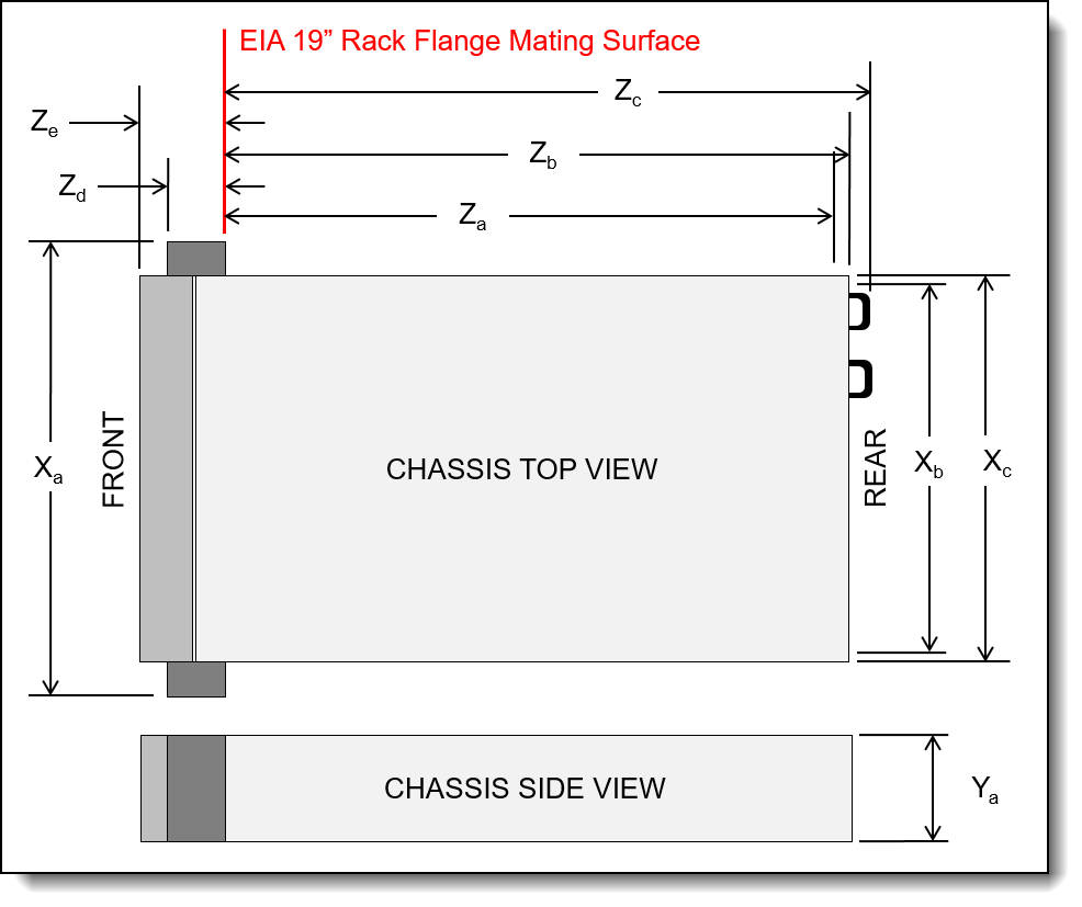
Figure 27. Server dimensions
The shipping dimensions (cardboard packaging) of the SR665 V3 are as follows:
- Width: 592 mm (23.3 inches)
- Height: 282 mm (11.1 inches)
- Depth: 992 mm (39.1 inches)
The server has the following weight:
- Maximum weight: 38.8 kg (85.5 lb)
Electrical specifications for AC input power supplies:
- Input voltage:
- 100 to 127 (nominal) Vac, 50 Hz or 60 Hz
- 200 to 240 (nominal) Vac, 50 Hz or 60 Hz
- 180 to 300 Vdc (China only)
- Inlet current: See the following table.
| Part number | Description | 100V AC | 200V AC | 220V AC | 240V DC |
|---|---|---|---|---|---|
| AC input power - 80 PLUS Titanium efficiency | |||||
| 4P57A82019 | ThinkSystem 750W 230V Titanium Hot-Swap Gen2 Power Supply v3 | No support | 4A | 3.6A | 3.3A |
| 4P57A72666 | ThinkSystem 1100W 230V Titanium Hot-Swap Gen2 Power Supply | No support | 5.9A | 5.3A | 5A |
| 4P57A78359 | ThinkSystem 1800W 230V Titanium Hot-Swap Gen2 Power Supply | No support | 9.7A | 8.7A | 8.3A |
| 4P57A72667 | ThinkSystem 2600W 230V Titanium Hot-Swap Gen2 Power Supply | No support | 13.2A | 13A | 11.9A |
| AC input power - 80 PLUS Platinum efficiency | |||||
| 4P57A72670 | ThinkSystem 750W 230V/115V Platinum Hot-Swap Gen2 Power Supply v3 | 8.4A | 4.1A | 3.69A | 3.5A |
| 4P57A72671 | ThinkSystem 1100W 230V/115V Platinum Hot-Swap Gen2 Power Supply v3 | 12A | 6A | 5.4A | 5.1A |
| 4P57A26294 | ThinkSystem 1800W 230V Platinum Hot-Swap Gen2 Power Supply v2 | No support | 10A | 9.1A | 9A |
| 4P57A26295 | ThinkSystem 2400W 230V Platinum Hot-Swap Gen2 Power Supply | No support | 14A | 12.6A | 12A |
Electrical specifications for DC input power supply:
- Input voltage: -48 to -60 Vdc
- Inlet current (1100W power supply): 26 A
Operating environment
The SR665 V3 server complies with ASHRAE Class A2 specifications with most configurations, and depending on the hardware configuration, also complies with ASHRAE Class A3 and Class A4 specifications. System performance may be impacted when operating temperature is outside ASHRAE A2 specification.
Depending on the hardware configuration, the SR665 V3 server also complies with ASHRAE Class H1 specification. System performance may be impacted when operating temperature is outside ASHRAE H1 specification.
Topics in this section:
Ambient temperature requirements
Additional restrictions to ASHRAE support, based on server configuration, are as follows:
- The ambient temperature must be limited to 35°C or lower if the server has any of the following components:
- Broadcom 57416 10GBASE-T 2-port OCP
- Broadcom 57454 10GBASE-T 4-port OCP
- PCIe network adapters at a rate greater than or equal to 100 Gb
- Parts with AOC and at the rate of 25 Gb
- The ambient temperature must be limited to 30°C or lower if the server has any of the following components:
- 24x 2.5" or 12x 3.5" front bay with middle or rear bay
- GPU (except front 24x 2.5" configurations and configurations with Group E processors)
- Parts with AOC and at a rate greater than 25 GB
- 9654(P)/9554(P)/9174F/9754/9734/9684X processors using performance heat sinks in a front 8x 2.5", 8x 3.5", or 16x 2.5" standard configuration.
- Group E processors using advanced heat sinks in a front 12x 3.5" or 24x 2.5" configuration without middle/rear bay
- The ambient temperature must be limited to 25°C or lower if the server has any of the following components:
- 9274F/9374F/9474F using performance heat sinks in a front 8x 2.5", 8x 3.5" or 16x 2.5" standard configuration
- 9654(P)/9554(P)/9174F/9754/9734 using performance heat sinks in a front 24x 2.5" configuration without middle/rear bay
- 9654(P)/9554(P)/9174F/9754/9734/9684X in a front 8x 2.5", 8x 3.5", 16x 2.5" + GPU configuration
- 24x 2.5" front bay + GPU
- Gen5 7.68 TB or larger capacity NVMe in a configuration with middle/rear bay
- Group A (240 W < cTDP ≤ 300 W) processor in a configuration with middle/rear bay
- ThinkSystem 256GB TruDDR5 4800MHz (8Rx4) 3DS RDIMM-A v1
Note:
- Group B processors: 200 W ≤ cTDP ≤ 240 W
- Group A processors: 240 W < cTDP ≤ 300 W
- Group E processors: 320 W ≤ cTDP ≤ 400 W
Server shutdown: When the ambient temperature is greater than the supported max temperature (ASHARE A4 45°C), the server will shut down. The server will not power on again until the ambient temperature falls within the supported temperature range.
For additional information, see the Environmental specifications and Thermal rules sections in the product documentation:
https://pubs.lenovo.com/sr665-v3/server_specifications_environmental
https://pubs.lenovo.com/sr665-v3/thermal_rules
Temperature and humidity
The server is supported in the following environment:
- Air temperature:
- Operating:
- ASHRAE Class A2: 10°C to 35°C (50°F to 95°F); the maximum ambient temperature decreases by 1°C for every 300 m (984 ft) increase in altitude above 900 m (2,953 ft).
- ASHRAE Class A3: 5°C to 40°C (41°F to 104°F); the maximum ambient temperature decreases by 1°C for every 175 m (574 ft) increase in altitude above 900 m (2,953 ft).
- ASHRAE Class A4: 5°C to 45°C (41°F to 113°F); the maximum ambient temperature decreases by 1°C for every 125 m (410 ft) increase in altitude above 900 m (2,953 ft).
- ASHRAE Class H1: 5 °C to 25 °C (41 °F to 77 °F); Decrease the maximum ambient temperature by 1°C for every 500 m (1640 ft) increase in altitude above 900 m (2,953 ft).
- Server off: 5°C to 45°C (41°F to 113°F)
- Shipment/storage: -40°C to 60°C (-40°F to 140°F)
- Operating:
- Maximum altitude: 3,050 m (10,000 ft)
- Relative Humidity (non-condensing):
- Operating
- ASHRAE Class A2: 8% to 80%; maximum dew point: 21°C (70°F)
- ASHRAE Class A3: 8% to 85%; maximum dew point: 24°C (75°F)
- ASHRAE Class A4: 8% to 90%; maximum dew point: 24°C (75°F)
- ASHRAE Class H1: 8% to 80%; Maximum dew point: 17°C (63°F)
- Shipment/storage: 8% to 90%
- Operating
Acoustical noise emissions
The server has the following acoustic noise emissions declaration:
- Sound power level (LWAd):
- Idling: 5.9 Bel (Min), 6.5 Bel (Typical), 7.3 Bel (GPU rich), 7.3 Bel (Storage rich)
- Operating: 6.5 Bel (Min), 8.1 Bel (Typical), 8.7 Bel (GPU rich), 7.5 Bel (Storage rich)
- Sound pressure level (LpAm):
- Idling: 41.5 dBA (Min), 51 dBA (Typical), 60.2 dBA (GPU rich), 60.2 dBA (Storage rich)
- Operating: 48.3 dBA (Min), 66.6 dBA (Typical), 71.9 dBA (GPU rich), 61.3 dBA (Storage rich)
Notes:
- These sound levels were measured in controlled acoustical environments according to procedures specified by ISO7779 and are reported in accordance with ISO 9296.
- The declared acoustic sound levels are based on the following configurations, which may change depending on configuration/conditions:
- Min: 2x 240W CPU, 12x 64GB RDIMMs, 8x SAS HDDs, RAID 940-8i, Intel E810-DA2 10/25GbE SFP28 2-Port OCP, 2x 1100W PSU
- Typical: 2x 300W CPU, 24x 64GB RDIMMs, 16x SAS HDDs, RAID 940-8i, Intel E810-DA2 10/25GbE SFP28 2-Port OCP, 2x 1800W PSU
- GPU rich: 2x 300W CPU, 24x 64GB RDIMMs, 16x SAS HDDs, RAID 940-16i, Intel E810-DA2 10/25GbE SFP28 2-Port OCP, 3x A100 80G GPUs, 2x 2400W PSU
- Storage rich: 2x 240W CPU, 12x 64GB RDIMMs, 16x SAS HDDs, RAID 940-8i, Intel E810-DA2 10/25GbE SFP28 2-Port OCP, 2x 1800W PSU
- Government regulations (such as those prescribed by OSHA or European Community Directives) may govern noise level exposure in the workplace and may apply to you and your server installation. The actual sound pressure levels in your installation depend upon a variety of factors, including the number of racks in the installation; the size, materials, and configuration of the room; the noise levels from other equipment; the room ambient temperature, and employee's location in relation to the equipment. Further, compliance with such government regulations depends on a variety of additional factors, including the duration of employees' exposure and whether employees wear hearing protection. Lenovo recommends that you consult with qualified experts in this field to determine whether you are in compliance with the applicable regulations.
Shock and vibration
The server has the following vibration and shock limits:
- Vibration:
- Operating: 0.21 G rms at 5 Hz to 500 Hz for 15 minutes across 3 axes
- Non-operating: 1.04 G rms at 2 Hz to 200 Hz for 15 minutes across 6 surfaces
- Shock:
- Operating: 15 G for 3 milliseconds in each direction (positive and negative X, Y, and Z axes)
- Non-operating:
- 23 kg - 31 kg: 35 G for 152 in./sec velocity change across 6 surfaces (3x GPU config, 2.5” config)
- 32 kg - 68 kg: 35 G for 136 in./sec velocity change across 6 surfaces (20x 3.5” HDD config)
Particulate contamination
Airborne particulates (including metal flakes or particles) and reactive gases acting alone or in combination with other environmental factors such as humidity or temperature might damage the system that might cause the system to malfunction or stop working altogether.
The following specifications indicate the limits of particulates that the system can tolerate:
- Reactive gases:
- The copper reactivity level shall be less than 200 Angstroms per month (Å/month)
- The silver reactivity level shall be less than 200 Å/month
- Airborne particulates:
- The room air should be continuously filtered with MERV 8 filters.
- Air entering a data center should be filtered with MERV 11 or preferably MERV 13 filters.
- The deliquescent relative humidity of the particulate contamination should be more than 60% RH
- Environment must be free of zinc whiskers
For additional information, see the Specifications section of the documentation for the server, available from the Lenovo Documents site, https://pubs.lenovo.com/
Water infrastructure for the Lenovo Neptune Processor DWC Module
The Lenovo Neptune Processor DWC Module is the liquid-based processor cooling offering for the SR665 V3, as described in the Lenovo Neptune Processor DWC Module section.
The DWC module requires the following water infrastructure components in the rack cabinet and data center:
- Supported 42U or 48U rack cabinet
The 42U or 48U Heavy Duty Rack Cabinet (machine types 7D6D or 7D6E) are supported. Two 0U mounting points are required for the water manifolds, at the rear of the rack cabinet, one either side.
For information about the 42U and 48U Heavy Duty Rack Cabinets, see the product guide:
https://lenovopress.lenovo.com/lp1498-lenovo-heavy-duty-rack-cabinets - 38-port water manifold, installed in the rear of the rack cabinet
The manifold provides quick-disconnect couplings that each server in the rack are connected to. Ordering information is in the table below.
- Coolant distribution unit (CDU), either in-rack or in-row
In-rack CDUs are installed at the bottom of the rack cabinet. The supported in-rack CDU is as follows:
- Lenovo Neptune DWC RM100 In-Rack CDU; see the RM100 In-Rack Coolant Distribution Unit section
In-row CDUs are separate cabinets that are typically installed at the end of a row of rack cabinets. Examples of suitable in-row CDUs include (but not limited to):
- CoolTera FS400 310KW CDU
- Vertiv Liebert XDU60 60KW CDU
- Hose kit to connect to the CDU to the manifold
Ordering information is in the table.
The following figure shows the major components of the solution.
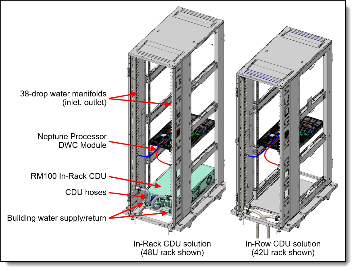
Figure 28. Water manifold connections
Configuration requirements:
- Maximum number of SR665 V3 servers support in a rack:
- 48U rack: 19 servers
- 42U rack with in-rack CDU: 18 servers
- 42U rack without in-rack CDU: 19 servers
- Inlet water flow rate:
- 0.5 LPM: Maximum 40°C inlet water temperature
- 1.0 LPM: Maximum 45°C inlet water temperature
- 1.5 LPM: Maximum 50°C inlet water temperature
- Water pressure requirement:
- Maximum operating node inlet pressure = 43.5 psi (3 Bar)
The 38-drop water manifold and hoses can be ordered as part numbers or by using the CTO process in the configurators using CTO model 7DE6CTO1WW. The following table lists the ordering information for the water manifold for the Neptune Processor DWC Module.
| Part number | Feature code (7DE6CTO1WW) |
Description |
|---|---|---|
| Manifold for 42U and 48U rack cabinet | ||
| 4XF7A90061 | BXHD | ThinkSystem Neptune DWC 38 Port Rack Manifold |
| Hoses to connect the manifold to an in-rack CDU | ||
| 4XF7A90232 | BXHE | Connection Set, for 38 Ports Manifold with in-Rack CDU in 42U Rack |
| 4XF7A90233 | BXHF | Connection Set, for 38 Ports Manifold with in-Rack CDU in 48U Rack |
| Hoses to connect the manifold to an in-row CDU | ||
| 4XF7A90234 | BXHG | Hose Set, 1 inch EPDM, 1.3m, for 38 Ports manifold for in-row CDU |
| 4XF7A90235 | BXHH | Hose Set, 1 inch EPDM, 2.3m, for 38 Ports manifold for in-row CDU |
Configuration notes:
- This water connection solution cannot be used with Lenovo's water-cooled servers as the water requirements are different.
- The hoses for in-row CDUs have Eaton FD83 quick-disconnect couplings
RM100 In-Rack Coolant Distribution Unit
The RM100 In-Rack Coolant Distribution Unit (CDU) can provide 100kW cooling capacity within the rack cabinet. It is designed as a 4U high rack device installed at the bottom of the rack. The CDU is supported in the 42U and 48U Heavy Duty Rack Cabinets.
For information about the 42U and 48U Heavy Duty Rack Cabinets, see the product guide:
https://lenovopress.lenovo.com/lp1498-lenovo-heavy-duty-rack-cabinets
The following figure shows the RM100 CDU.

Figure 29. RM100 In-Rack Coolant Distribution Unit
The CDU can be ordered using the CTO process in the configurators using machine type 7DBL. The following table lists the base CTO model and base feature code.
| CTO model | Base feature | Description |
|---|---|---|
| 7DBLCTOLWW | BRL4 | Lenovo Neptune DWC RM100 In-Rack CDU |
For details and exact specification of the CDU, see the In-Rack CDU Operation & Maintenance Guide:
https://pubs.lenovo.com/hdc_rackcabinet/rm100_user_guide.pdf
Professional Services: The factory integration of the In-Rack CDU requires Lenovo Professional Services review and approval for warranty and associated extended services. Before ordering CDU and manifold, contact the Lenovo Professional Services team ( ).
Warranty and Support
The SR665 V3 has a 1-year or 3-year warranty based on the machine type of the system:
- 7D9B - 1 year warranty
- 7D9A - 3 year warranty
The standard warranty terms are customer-replaceable unit (CRU) and onsite (for field-replaceable units FRUs only) with standard call center support during normal business hours and 9x5 Next Business Day Parts Delivered.
Lenovo’s additional support services provide a sophisticated, unified support structure for your data center, with an experience consistently ranked number one in customer satisfaction worldwide. Available offerings include:
- Premier Support
Premier Support provides a Lenovo-owned customer experience and delivers direct access to technicians skilled in hardware, software, and advanced troubleshooting, in addition to the following:
- Direct technician-to-technician access through a dedicated phone line
- 24x7x365 remote support
- Single point of contact service
- End to end case management
- Third-party collaborative software support
- Online case tools and live chat support
- On-demand remote system analysis
- Warranty Upgrade (Preconfigured Support)
Services are available to meet the on-site response time targets that match the criticality of your systems.
- 3, 4, or 5 years of service coverage
- 1-year or 2-year post-warranty extensions
- Foundation Service: 9x5 service coverage with next business day onsite response. YourDrive YourData is an optional extra (see below).
- Essential Service: 24x7 service coverage with 4-hour onsite response or 24-hour committed repair (available only in select markets). Bundled with YourDrive YourData.
- Advanced Service: 24x7 service coverage with 2-hour onsite response or 6-hour committed repair (available only in select markets). Bundled with YourDrive YourData.
- Managed Services
Lenovo Managed Services provides continuous 24x7 remote monitoring (plus 24x7 call center availability) and proactive management of your data center using state-of-the-art tools, systems, and practices by a team of highly skilled and experienced Lenovo services professionals.
Quarterly reviews check error logs, verify firmware & OS device driver levels, and software as needed. We’ll also maintain records of latest patches, critical updates, and firmware levels, to ensure you systems are providing business value through optimized performance.
- Technical Account Management (TAM)
A Lenovo Technical Account Manager helps you optimize the operation of your data center based on a deep understanding of your business. You gain direct access to your Lenovo TAM, who serves as your single point of contact to expedite service requests, provide status updates, and furnish reports to track incidents over time. In addition, your TAM will help proactively make service recommendations and manage your service relationship with Lenovo to make certain your needs are met.
- Enterprise Server Software Support
Enterprise Software Support is an additional support service providing customers with software support on Microsoft, Red Hat, SUSE, and VMware applications and systems. Around the clock availability for critical problems plus unlimited calls and incidents helps customers address challenges fast, without incremental costs. Support staff can answer troubleshooting and diagnostic questions, address product comparability and interoperability issues, isolate causes of problems, report defects to software vendors, and more.
- YourDrive YourData
Lenovo’s YourDrive YourData is a multi-drive retention offering that ensures your data is always under your control, regardless of the number of drives that are installed in your Lenovo server. In the unlikely event of a drive failure, you retain possession of your drive while Lenovo replaces the failed drive part. Your data stays safely on your premises, in your hands. The YourDrive YourData service can be purchased in convenient bundles and is optional with Foundation Service. It is bundled with Essential Service and Advanced Service.
- Health Check
Having a trusted partner who can perform regular and detailed health checks is central to maintaining efficiency and ensuring that your systems and business are always running at their best. Health Check supports Lenovo-branded server, storage, and networking devices, as well as select Lenovo-supported products from other vendors that are sold by Lenovo or a Lenovo-Authorized Reseller.
Examples of region-specific warranty terms are second or longer business day parts delivery or parts-only base warranty.
If warranty terms and conditions include onsite labor for repair or replacement of parts, Lenovo will dispatch a service technician to the customer site to perform the replacement. Onsite labor under base warranty is limited to labor for replacement of parts that have been determined to be field-replaceable units (FRUs). Parts that are determined to be customer-replaceable units (CRUs) do not include onsite labor under base warranty.
If warranty terms include parts-only base warranty, Lenovo is responsible for delivering only replacement parts that are under base warranty (including FRUs) that will be sent to a requested location for self-service. Parts-only service does not include a service technician being dispatched onsite. Parts must be changed at customer’s own cost and labor and defective parts must be returned following the instructions supplied with the spare parts.
Lenovo Service offerings are region-specific. Not all preconfigured support and upgrade options are available in every region. For information about Lenovo service upgrade offerings that are available in your region, refer to the following resources:
- Service part numbers in Lenovo Data Center Solution Configurator (DCSC):
http://dcsc.lenovo.com/#/services - Lenovo Services Availability Locator
http://lenovolocator.com/
For service definitions, region-specific details, and service limitations, please refer to the following documents:
- Lenovo Statement of Limited Warranty for Infrastructure Solutions Group (ISG) Servers and System Storage
http://pcsupport.lenovo.com/us/en/solutions/ht503310 - Lenovo Data Center Services Agreement
http://support.lenovo.com/us/en/solutions/ht116628
Services
Lenovo Services is a dedicated partner to your success. Our goal is to reduce your capital outlays, mitigate your IT risks, and accelerate your time to productivity.
Note: Some service options may not be available in all markets or regions. For more information, go to https://www.lenovo.com/services. For information about Lenovo service upgrade offerings that are available in your region, contact your local Lenovo sales representative or business partner.
Here’s a more in-depth look at what we can do for you:
- Asset Recovery Services
Asset Recovery Services (ARS) helps customers recover the maximum value from their end-of-life equipment in a cost-effective and secure way. On top of simplifying the transition from old to new equipment, ARS mitigates environmental and data security risks associated with data center equipment disposal. Lenovo ARS is a cash-back solution for equipment based on its remaining market value, yielding maximum value from aging assets and lowering total cost of ownership for your customers. For more information, see the ARS page, https://lenovopress.com/lp1266-reduce-e-waste-and-grow-your-bottom-line-with-lenovo-ars.
- Assessment Services
An Assessment helps solve your IT challenges through an onsite, multi-day session with a Lenovo technology expert. We perform a tools-based assessment which provides a comprehensive and thorough review of a company's environment and technology systems. In addition to the technology based functional requirements, the consultant also discusses and records the non-functional business requirements, challenges, and constraints. Assessments help organizations like yours, no matter how large or small, get a better return on your IT investment and overcome challenges in the ever-changing technology landscape.
- Design Services
Professional Services consultants perform infrastructure design and implementation planning to support your strategy. The high-level architectures provided by the assessment service are turned into low level designs and wiring diagrams, which are reviewed and approved prior to implementation. The implementation plan will demonstrate an outcome-based proposal to provide business capabilities through infrastructure with a risk-mitigated project plan.
- Basic Hardware Installation
Lenovo experts can seamlessly manage the physical installation of your server, storage, or networking hardware. Working at a time convenient for you (business hours or off shift), the technician will unpack and inspect the systems on your site, install options, mount in a rack cabinet, connect to power and network, check and update firmware to the latest levels, verify operation, and dispose of the packaging, allowing your team to focus on other priorities.
- Deployment Services
When investing in new IT infrastructures, you need to ensure your business will see quick time to value with little to no disruption. Lenovo deployments are designed by development and engineering teams who know our Products & Solutions better than anyone else, and our technicians own the process from delivery to completion. Lenovo will conduct remote preparation and planning, configure & integrate systems, validate systems, verify and update appliance firmware, train on administrative tasks, and provide post-deployment documentation. Customer’s IT teams leverage our skills to enable IT staff to transform with higher level roles and tasks.
- Integration, Migration, and Expansion Services
Move existing physical & virtual workloads easily, or determine technical requirements to support increased workloads while maximizing performance. Includes tuning, validation, and documenting ongoing run processes. Leverage migration assessment planning documents to perform necessary migrations.
Regulatory compliance
The SR665 V3 conforms to the following standards:
- ANSI/UL 62368-1
- IEC 62368-1 (CB Certificate and CB Test Report)
- CSA C22.2 No. 62368-1
- Mexico NOM-019
- India BIS 13252 (Part 1)
- Germany GS
- TUV-GS (EN62368-1, and EK1-ITB2000)
- Brazil INMETRO
- Ukraine UkrCEPRO
- Morocco CMIM Certification (CM)
- Russia, Belorussia and Kazakhstan, TP EAC 037/2016 (for RoHS)
- Russia, Belorussia and Kazakhstan, EAC: TP TC 004/2011 (for Safety); TP TC 020/2011 (for EMC)
- CE, UKCA Mark (EN55032 Class A, EN62368-1, EN55024, EN55035, EN61000-3-2, EN61000-3-3, (EU) 2019/424, and EN IEC 63000 (RoHS))
- FCC - Verified to comply with Part 15 of the FCC Rules, Class A
- Canada ICES-003, issue 7, Class A
- CISPR 32, Class A, CISPR 35
- Korea KN32, Class A, KN35
- Japan VCCI, Class A
- Taiwan BSMI CNS15936, Class A; CNS15598-1; Section 5 of CNS15663
- Australia/New Zealand AS/NZS CISPR 32, Class A; AS/NZS 62368.1
- UL Green Guard, UL2819
- Energy Star 4.0
- EPEAT (NSF/ ANSI 426) Bronze
- Japanese Energy-Saving Act
- China CCC certificate, GB17625.1; GB4943.1; GB/T9254
- China CECP certificate, CQC3135
- China CELP certificate, HJ 2507-2011
External drive enclosures
The server supports attachment to external drive enclosures using a RAID controller with external ports or a SAS host bus adapter. Adapters supported by the server are listed in the SAS adapters for external storage section.
Note: Information provided in this section is for ordering reference purposes only. For the operating system and adapter support details, refer to the interoperability matrix for a particular storage enclosure that can be found on the Lenovo Data Center Support web site:
http://datacentersupport.lenovo.com
| Model | Description |
|---|---|
| 4587HC1 | Lenovo Storage D1212 Disk Expansion Enclosure (2U enclosure with 12x LFF drive bays) |
| 4587HC2 | Lenovo Storage D1224 Disk Expansion Enclosure (2U enclosure with 24x SFF drive bays) |
| 6413HC1 | Lenovo Storage D3284 High Density Expansion Enclosure (5U enclosure with 84x LFF drive bays) |
| 7DAHCTO1WW | Lenovo ThinkSystem D4390 Direct Attached Storage (4U enclosure with 90x LFF drive bays) |
For details about supported drives, adapters, and cables, see the following Lenovo Press Product Guides:
- Lenovo Storage D1212 and D1224
http://lenovopress.lenovo.com/lp0512 - Lenovo Storage D3284
http://lenovopress.lenovo.com/lp0513 - Lenovo ThinkSystem D4390
https://lenovopress.lenovo.com/lp1681
External storage systems
Lenovo offers the ThinkSystem DE Series and ThinkSystem DM Series external storage systems for high-performance storage. See the DE Series and DM Series product guides for specific controller models, expansion enclosures and configuration options:
- ThinkSystem DE Series Storage
https://lenovopress.com/storage/thinksystem/de-series#rt=product-guide - ThinkSystem DM Series Storage
https://lenovopress.com/storage/thinksystem/dm-series#rt=product-guide - ThinkSystem DG Series Storage
https://lenovopress.com/storage/thinksystem/dg-series#rt=product-guide
External backup units
The following table lists the external backup options that are offered by Lenovo.
| Part number | Description |
|---|---|
| External RDX USB drives | |
| 4T27A10725 | ThinkSystem RDX External USB 3.0 Dock |
| External SAS tape backup drives | |
| 6160S7E | IBM TS2270 Tape Drive Model H7S |
| 6160S8E | IBM TS2280 Tape Drive Model H8S |
| 6160S9E | IBM TS2290 Tape Drive Model H9S |
| External SAS tape backup autoloaders | |
| 6171S7R | IBM TS2900 Tape Autoloader w/LTO7 HH SAS |
| 6171S8R | IBM TS2900 Tape Autoloader w/LTO8 HH SAS |
| 6171S9R | IBM TS2900 Tape Autoloader w/LTO9 HH SAS |
| External tape backup libraries | |
| 6741A1F | IBM TS4300 3U Tape Library-Base Unit |
| 6741A3F | IBM TS4300 3U Tape Library-Expansion Unit |
| Full High 8 Gb Fibre Channel for TS4300 | |
| 01KP938 | LTO 7 FH Fibre Channel Drive |
| 01KP954 | LTO 8 FH Fibre Channel Drive |
| 02JH837 | LTO 9 FH Fibre Channel Drive |
| Half High 8 Gb Fibre Channel for TS4300 | |
| 01KP936 | LTO 7 HH Fibre Channel Drive |
| 01KP952 | LTO 8 HH Fibre Channel Drive |
| 02JH835 | LTO 9 HH Fibre Channel Drive |
| Half High 6 Gb SAS for TS4300 | |
| 01KP937 | LTO 7 HH SAS Drive |
| 01KP953 | LTO 8 HH SAS Drive |
| 02JH836 | LTO 9 HH SAS Drive |
For more information, see the list of Product Guides in the Backup units category:
https://lenovopress.com/servers/options/backup
Fibre Channel SAN switches
Lenovo offers the ThinkSystem DB Series of Fibre Channel SAN switches for high-performance storage expansion. See the DB Series product guides for models and configuration options:
- ThinkSystem DB Series SAN Switches:
https://lenovopress.com/storage/switches/rack#rt=product-guide
Uninterruptible power supply units
The following table lists the uninterruptible power supply (UPS) units that are offered by Lenovo.
| Part number | Description |
|---|---|
| 55941AX | RT1.5kVA 2U Rack or Tower UPS (100-125VAC) |
| 55941KX | RT1.5kVA 2U Rack or Tower UPS (200-240VAC) |
| 55942AX | RT2.2kVA 2U Rack or Tower UPS (100-125VAC) |
| 55942KX | RT2.2kVA 2U Rack or Tower UPS (200-240VAC) |
| 55943AX | RT3kVA 2U Rack or Tower UPS (100-125VAC) |
| 55943KX | RT3kVA 2U Rack or Tower UPS (200-240VAC) |
| 55945KX | RT5kVA 3U Rack or Tower UPS (200-240VAC) |
| 55946KX | RT6kVA 3U Rack or Tower UPS (200-240VAC) |
| 55948KX | RT8kVA 6U Rack or Tower UPS (200-240VAC) |
| 55949KX | RT11kVA 6U Rack or Tower UPS (200-240VAC) |
| 55948PX | RT8kVA 6U 3:1 Phase Rack or Tower UPS (380-415VAC) |
| 55949PX | RT11kVA 6U 3:1 Phase Rack or Tower UPS (380-415VAC) |
| 55943KT† | ThinkSystem RT3kVA 2U Standard UPS (200-230VAC) (2x C13 10A, 2x GB 10A, 1x C19 16A outlets) |
| 55943LT† | ThinkSystem RT3kVA 2U Long Backup UPS (200-230VAC) (2x C13 10A, 2x GB 10A, 1x C19 16A outlets) |
| 55946KT† | ThinkSystem RT6kVA 5U UPS (200-230VAC) (2x C13 10A outlets, 1x Terminal Block output) |
| 5594XKT† | ThinkSystem RT10kVA 5U UPS (200-230VAC) (2x C13 10A outlets, 1x Terminal Block output) |
† Only available in China and the Asia Pacific market.
For more information, see the list of Product Guides in the UPS category:
https://lenovopress.com/servers/options/ups
Power distribution units
The following table lists the power distribution units (PDUs) that are offered by Lenovo.
| Part number |
Feature code |
Description |
ANZ
|
ASEAN
|
Brazil
|
EET
|
MEA
|
RUCIS
|
WE
|
HTK
|
INDIA
|
JAPAN
|
LA
|
NA
|
PRC
|
|---|---|---|---|---|---|---|---|---|---|---|---|---|---|---|---|
| 0U Basic PDUs | |||||||||||||||
| 00YJ776 | ATZY | 0U 36 C13/6 C19 24A 1 Phase PDU | N | Y | Y | N | N | N | N | N | N | Y | Y | Y | N |
| 00YJ779 | ATZX | 0U 21 C13/12 C19 48A 3 Phase PDU | N | N | Y | N | N | N | Y | N | N | Y | Y | Y | N |
| 00YJ777 | ATZZ | 0U 36 C13/6 C19 32A 1 Phase PDU | Y | Y | N | Y | Y | Y | Y | Y | Y | N | N | Y | Y |
| 00YJ778 | AU00 | 0U 21 C13/12 C19 32A 3 Phase PDU | Y | Y | N | Y | Y | Y | Y | Y | Y | N | N | Y | Y |
| 0U Switched and Monitored PDUs | |||||||||||||||
| 00YJ783 | AU04 | 0U 12 C13/12 C19 Switched and Monitored 48A 3 Phase PDU | N | N | Y | N | N | N | Y | N | N | Y | Y | Y | N |
| 00YJ781 | AU03 | 0U 20 C13/4 C19 Switched and Monitored 24A 1 Phase PDU | N | N | Y | N | Y | N | Y | N | N | Y | Y | Y | N |
| 00YJ782 | AU02 | 0U 18 C13/6 C19 Switched and Monitored 32A 3 Phase PDU | Y | Y | Y | Y | Y | Y | Y | Y | Y | N | Y | N | Y |
| 00YJ780 | AU01 | 0U 20 C13/4 C19 Switched and Monitored 32A 1 Phase PDU | Y | Y | Y | Y | Y | Y | Y | Y | Y | N | Y | N | Y |
| 1U Switched and Monitored PDUs | |||||||||||||||
| 4PU7A81117 | BNDV | 1U 18 C19/C13 switched and monitored 48A 3P WYE PDU - ETL | N | N | N | N | N | N | N | N | N | N | N | Y | N |
| 4PU7A77467 | BLC4 | 1U 18 C19/C13 Switched and Monitored 80A 3P Delta PDU | N | N | N | N | N | N | N | N | N | Y | N | Y | N |
| 4PU7A77469 | BLC6 | 1U 12 C19/C13 switched and monitored 60A 3P Delta PDU | N | N | N | N | N | N | N | N | N | N | N | Y | N |
| 4PU7A77468 | BLC5 | 1U 12 C19/C13 switched and monitored 32A 3P WYE PDU | Y | Y | Y | Y | Y | Y | Y | Y | Y | N | Y | Y | Y |
| 4PU7A81118 | BNDW | 1U 18 C19/C13 switched and monitored 48A 3P WYE PDU - CE | Y | Y | Y | Y | Y | Y | Y | Y | Y | N | Y | N | Y |
| 46M4002 | 5896 | 1U 9 C19/3 C13 Switched and Monitored DPI PDU | Y | Y | Y | Y | Y | Y | Y | Y | Y | Y | Y | Y | Y |
| 46M4004 | 5894 | 1U 12 C13 Switched and Monitored DPI PDU | Y | Y | Y | Y | Y | Y | Y | Y | Y | Y | Y | Y | Y |
| 46M4003 | 5897 | 1U 9 C19/3 C13 Switched and Monitored 60A 3 Phase PDU | Y | Y | Y | Y | Y | Y | Y | Y | Y | Y | Y | Y | Y |
| 46M4005 | 5895 | 1U 12 C13 Switched and Monitored 60A 3 Phase PDU | Y | Y | Y | Y | Y | Y | Y | Y | Y | Y | Y | Y | Y |
| 1U Ultra Density Enterprise PDUs (9x IEC 320 C13 + 3x IEC 320 C19 outlets) | |||||||||||||||
| 71763NU | 6051 | Ultra Density Enterprise C19/C13 PDU 60A/208V/3PH | N | N | Y | N | N | N | N | N | N | Y | Y | Y | N |
| 71762NX | 6091 | Ultra Density Enterprise C19/C13 PDU Module | Y | Y | Y | Y | Y | Y | Y | Y | Y | Y | Y | Y | Y |
| 1U C13 Enterprise PDUs (12x IEC 320 C13 outlets) | |||||||||||||||
| 39M2816 | 6030 | DPI C13 Enterprise PDU Plus Module (WW) | Y | Y | Y | Y | Y | Y | Y | Y | Y | Y | Y | Y | Y |
| 39Y8941 | 6010 | DPI C13 Enterprise PDU Module (WW) | Y | Y | Y | Y | Y | Y | Y | Y | Y | Y | Y | Y | Y |
| 1U C19 Enterprise PDUs (6x IEC 320 C19 outlets) | |||||||||||||||
| 39Y8948 | 6060 | DPI C19 Enterprise PDU Module (WW) | Y | Y | Y | Y | Y | Y | Y | Y | Y | Y | Y | Y | Y |
| 39Y8923 | 6061 | DPI Three-phase 60A/208V C19 Enterprise PDU (US) | N | N | Y | N | N | N | Y | N | N | N | Y | Y | N |
| 1U Front-end PDUs (3x IEC 320 C19 outlets) | |||||||||||||||
| 39Y8938 | 6002 | DPI Single-phase 30A/120V Front-end PDU (US) | Y | Y | Y | Y | Y | Y | Y | Y | Y | Y | Y | Y | Y |
| 39Y8939 | 6003 | DPI Single-phase 30A/208V Front-end PDU (US) | Y | Y | Y | Y | Y | Y | Y | Y | Y | Y | Y | Y | Y |
| 39Y8934 | 6005 | DPI Single-phase 32A/230V Front-end PDU (International) | Y | Y | Y | Y | Y | Y | Y | Y | Y | Y | Y | Y | Y |
| 39Y8940 | 6004 | DPI Single-phase 60A/208V Front-end PDU (US) | Y | N | Y | Y | Y | Y | Y | N | N | Y | Y | Y | N |
| 39Y8935 | 6006 | DPI Single-phase 63A/230V Front-end PDU (International) | Y | Y | Y | Y | Y | Y | Y | Y | Y | Y | Y | Y | Y |
| 1U NEMA PDUs (6x NEMA 5-15R outlets) | |||||||||||||||
| 39Y8905 | 5900 | DPI 100-127V NEMA PDU | Y | Y | Y | Y | Y | Y | Y | Y | Y | Y | Y | Y | Y |
| Line cords for 1U PDUs that ship without a line cord | |||||||||||||||
| 40K9611 | 6504 | 4.3m, 32A/380-415V, EPDU/IEC 309 3P+N+G 3ph wye (non-US) Line Cord | Y | Y | Y | Y | Y | Y | Y | Y | Y | Y | Y | Y | Y |
| 40K9612 | 6502 | 4.3m, 32A/230V, EPDU to IEC 309 P+N+G (non-US) Line Cord | Y | Y | Y | Y | Y | Y | Y | Y | Y | Y | Y | Y | Y |
| 40K9613 | 6503 | 4.3m, 63A/230V, EPDU to IEC 309 P+N+G (non-US) Line Cord | Y | Y | Y | Y | Y | Y | Y | Y | Y | Y | Y | Y | Y |
| 40K9614 | 6500 | 4.3m, 30A/208V, EPDU to NEMA L6-30P (US) Line Cord | Y | Y | Y | Y | Y | Y | Y | Y | Y | Y | Y | Y | Y |
| 40K9615 | 6501 | 4.3m, 60A/208V, EPDU to IEC 309 2P+G (US) Line Cord | N | N | Y | N | N | N | Y | N | N | Y | Y | Y | N |
| 40K9617 | 6505 | 4.3m, 32A/230V, Souriau UTG Female to AS/NZ 3112 (Aus/NZ) Line Cord | Y | Y | Y | Y | Y | Y | Y | Y | Y | Y | Y | Y | Y |
| 40K9618 | 6506 | 4.3m, 32A/250V, Souriau UTG Female to KSC 8305 (S. Korea) Line Cord | Y | Y | Y | Y | Y | Y | Y | Y | Y | Y | Y | Y | Y |
For more information, see the Lenovo Press documents in the PDU category:
https://lenovopress.com/servers/options/pdu
Rack cabinets
The following table lists the supported rack cabinets.
| Part number | Description |
|---|---|
| 93072RX | 25U Standard Rack (1000mm) |
| 93072PX | 25U Static S2 Standard Rack (1000mm) |
| 7D6DA007WW | ThinkSystem 42U Onyx Primary Heavy Duty Rack Cabinet (1200mm) |
| 7D6DA008WW | ThinkSystem 42U Pearl Primary Heavy Duty Rack Cabinet (1200mm) |
| 1410-O42 | Lenovo EveryScale 42U Onyx Heavy Duty Rack Cabinet |
| 1410-P42 | Lenovo EveryScale 42U Pearl Heavy Duty Rack Cabinet |
| 93604PX | 42U 1200mm Deep Dynamic Rack |
| 93614PX | 42U 1200mm Deep Static Rack |
| 93634PX | 42U 1100mm Dynamic Rack |
| 93634EX | 42U 1100mm Dynamic Expansion Rack |
| 93074RX | 42U Standard Rack (1000mm) |
| 7D6EA009WW | ThinkSystem 48U Onyx Primary Heavy Duty Rack Cabinet (1200mm) |
| 7D6EA00AWW | ThinkSystem 48U Pearl Primary Heavy Duty Rack Cabinet (1200mm) |
| 1410-O48 | Lenovo EveryScale 48U Onyx Heavy Duty Rack Cabinet |
| 1410-P48 | Lenovo EveryScale 48U Pearl Heavy Duty Rack Cabinet |
For specifications about these racks, see the Lenovo Rack Cabinet Reference, available from:
https://lenovopress.com/lp1287-lenovo-rack-cabinet-reference
For more information, see the list of Product Guides in the Rack cabinets category:
https://lenovopress.com/servers/options/racks
KVM console options
The following table lists the supported KVM consoles.
| Part number | Description |
|---|---|
| Consoles | |
| 4XF7A84188 | ThinkSystem 18.5" LCD Console (with US English keyboard) |
| 4XF7A73009 | ThinkSystem 18.5" LCD console (with US English keyboard) |
| 17238BX | 1U 18.5" Standard Console (without keyboard - see the next table) |
The following table lists the keyboards supported with the 1U 18.5" Standard Console (now withdrawn).
Note: These keyboards are not supported with the ThinkSystem 18.5" LCD Console.
| Part number | Description |
|---|---|
| 7ZB7A05469 | ThinkSystem Keyboard w/ Int.Pointing Device USB - Arabic 253 RoHS v2 |
| 7ZB7A05468 | ThinkSystem Keyboard w/ Int. Pointing Device USB - Belg/UK 120 RoHS v2 |
| 7ZB7A05206 | ThinkSystem Keyboard w/ Int. Pointing Device USB - Czech 489 RoHS v2 |
| 7ZB7A05207 | ThinkSystem Keyboard w/ Int. Pointing Device USB - Danish 159 RoHS v2 |
| 7ZB7A05208 | ThinkSystem Keyboard w/ Int. Pointing Device USB - Dutch 143 RoHS v2 |
| 7ZB7A05210 | ThinkSystem Keyboard w/ Int. Pointing Device USB - Fr/Canada 445 RoHS v2 |
| 7ZB7A05209 | ThinkSystem Keyboard w/ Int. Pointing Device USB - French 189 RoHS v2 |
| 7ZB7A05211 | ThinkSystem Keyboard w/ Int. Pointing Device USB - German 129 RoHS v2 |
| 7ZB7A05212 | ThinkSystem Keyboard w/ Int. Pointing Device USB - Greek 219 RoHS v2 |
| 7ZB7A05213 | ThinkSystem Keyboard w/ Int. Pointing Device USB - Hebrew 212 RoHS v2 |
| 7ZB7A05214 | ThinkSystem Keyboard w/ Int. Pointing Device USB - Hungarian 208 RoHS v2 |
| 7ZB7A05215 | ThinkSystem Keyboard w/ Int. Pointing Device USB - Italian 141 RoHS v2 |
| 7ZB7A05216 | ThinkSystem Keyboard w/ Int. Pointing Device USB - Japanese 194 RoHS v2 |
| 7ZB7A05217 | ThinkSystem Keyboard w/ Int. Pointing Device USB - Korean 413 RoHS v2 |
| 7ZB7A05218 | ThinkSystem Keyboard w/ Int. Pointing Device USB - LA Span 171 RoHS v2 |
| 7ZB7A05219 | ThinkSystem Keyboard w/ Int. Pointing Device USB - Norwegian 155 RoHS v2 |
| 7ZB7A05220 | ThinkSystem Keyboard w/ Int. Pointing Device USB - Polish 214 RoHS v2 |
| 7ZB7A05221 | ThinkSystem Keyboard w/ Int. Pointing Device USB - Portugese 163 RoHS v2 |
| 7ZB7A05222 | ThinkSystem Keyboard w/ Int. Pointing Device USB - Russian 441 RoHS v2 |
| 7ZB7A05223 | ThinkSystem Keyboard w/ Int. Pointing Device USB - Slovak 245 RoHS v2 |
| 7ZB7A05231 | ThinkSystem Keyboard w/ Int. Pointing Device USB - Slovenian 234 RoHS v2 |
| 7ZB7A05224 | ThinkSystem Keyboard w/ Int. Pointing Device USB - Spanish 172 RoHS v2 |
| 7ZB7A05225 | ThinkSystem Keyboard w/ Int. Pointing Device USB - Swed/Finn 153 RoHS v2 |
| 7ZB7A05226 | ThinkSystem Keyboard w/ Int. Pointing Device USB - Swiss F/G 150 RoHS v2 |
| 7ZB7A05227 | ThinkSystem Keyboard w/ Int. Pointing Device USB - Thai 191 RoHS v2 |
| 7ZB7A05467 | ThinkSystem Keyboard with Int. Pointing Device USB - Trad Chinese/US 467 RoHS v2 |
| 7ZB7A05228 | ThinkSystem Keyboard w/ Int. Pointing Device USB - Turkish 179 RoHS v2 |
| 7ZB7A05229 | ThinkSystem Keyboard w/ Int. Pointing Device USB - UK Eng 166 RoHS v2 |
| 7ZB7A05470 | ThinkSystem Keyboard w/ Int. Pointing Device USB - US Eng 103P RoHS v2 |
| 7ZB7A05230 | ThinkSystem Keyboard w/ Int. Pointing Device USB - US Euro 103P RoHS v2 |
The following table lists the available KVM switches and the options that are supported with them.
| Part number | Description |
|---|---|
| KVM Console switches | |
| 1754D1T | ThinkSystem Digital 2x1x16 KVM Switch (DVI video output port) |
| 1754A1T | ThinkSystem Analog 1x8 KVM Switch (DVI video output port) |
| 1754D2X | Global 4x2x32 Console Manager (GCM32) |
| 1754D1X | Global 2x2x16 Console Manager (GCM16) |
| 1754A2X | Local 2x16 Console Manager (LCM16) |
| 1754A1X | Local 1x8 Console Manager (LCM8) |
| Cables for ThinkSystem Digital and Analog KVM Console switches | |
| 4X97A11108 | ThinkSystem VGA to DVI Conversion Cable |
| 4X97A11109 | ThinkSystem Single-USB Conversion Cable for Digital KVM |
| 4X97A11107 | ThinkSystem Dual-USB Conversion Cable for Digital KVM |
| 4X97A11106 | ThinkSystem USB Conversion Cable for Analog KVM |
| Cables for GCM and LCM Console switches | |
| 43V6147 | Single Cable USB Conversion Option (UCO) |
| 39M2895 | USB Conversion Option Pack |
| 46M5383 | Virtual Media Conversion Option Gen2 (VCO2) |
| 46M5382 | Serial Conversion Option (SCO) |
For more information, see the list of Product Guides in the KVM Switches and Consoles category:
http://lenovopress.com/servers/options/kvm
Lenovo Financial Services
Lenovo Financial Services reinforces Lenovo’s commitment to deliver pioneering products and services that are recognized for their quality, excellence, and trustworthiness. Lenovo Financial Services offers financing solutions and services that complement your technology solution anywhere in the world.
We are dedicated to delivering a positive finance experience for customers like you who want to maximize your purchase power by obtaining the technology you need today, protect against technology obsolescence, and preserve your capital for other uses.
We work with businesses, non-profit organizations, governments and educational institutions to finance their entire technology solution. We focus on making it easy to do business with us. Our highly experienced team of finance professionals operates in a work culture that emphasizes the importance of providing outstanding customer service. Our systems, processes and flexible policies support our goal of providing customers with a positive experience.
We finance your entire solution. Unlike others, we allow you to bundle everything you need from hardware and software to service contracts, installation costs, training fees, and sales tax. If you decide weeks or months later to add to your solution, we can consolidate everything into a single invoice.
Our Premier Client services provide large accounts with special handling services to ensure these complex transactions are serviced properly. As a premier client, you have a dedicated finance specialist who manages your account through its life, from first invoice through asset return or purchase. This specialist develops an in-depth understanding of your invoice and payment requirements. For you, this dedication provides a high-quality, easy, and positive financing experience.
For your region-specific offers, please ask your Lenovo sales representative or your technology provider about the use of Lenovo Financial Services. For more information, see the following Lenovo website:
https://www.lenovo.com/us/en/landingpage/lenovo-financial-services/
Seller training courses
The following sales training courses are offered for employees and partners (login required). Courses are listed in date order.
-
Partner Technical Webinar - ISG Portfolio Update
2024-04-15 | 60 minutes | Employees and Partners
DetailsPartner Technical Webinar - ISG Portfolio UpdateIn this 60-minute replay, Mark Bica, NA ISG Server Product Manager reviewed the Lenovo ISG portfolio. He covered new editions such as the SR680a \ SR685a, dense servers, and options that are strategic for any workload.
Published: 2024-04-15
Length: 60 minutes
Employee link: Grow@Lenovo
Partner link: Lenovo Partner Learning
Course code: 041224 -
Partner Technical Webinar – StorMagic
2024-03-19 | 60 minutes | Employees and Partners
DetailsPartner Technical Webinar – StorMagicMarch 08, 2024 – In this 60-minute replay, Stuart Campbell and Wes Ganeko of StorMagic joined us and provided an overview of StorMagic on Lenovo. They also demonstrated the interface while sharing some interesting use cases.
Published: 2024-03-19
Length: 60 minutes
Employee link: Grow@Lenovo
Partner link: Lenovo Partner Learning
Course code: 030824 -
Intel Transparent Supply Chain on Lenovo Servers
2024-01-29 | 12 minutes | Employees and Partners
DetailsIntel Transparent Supply Chain on Lenovo ServersThis course introduces the Intel Transparent Supply Chain (TSC) program, explains how the program works, and discusses the benefits of the Intel TSC program to customers. Adding the Intel TSC feature to an order is explained.
Published: 2024-01-29
Course objectives:
• Describe the Intel® Transparent Supply Chain program
• Explain how the Intel® Transparent Supply Chain program works
• Discuss the benefits of the Intel® Transparent Supply Chain program to Lenovo customers
• Explain how to add Intel® Transparent Supply Chain program feature to an order
Length: 12 minutes
Employee link: Grow@Lenovo
Partner link: Lenovo Partner Learning
Course code: SXXW1230 -
Family Portfolio: Storage Controller Options
2024-01-23 | 25 minutes | Employees and Partners
DetailsFamily Portfolio: Storage Controller OptionsThis course covers the storage controller options available for use in Lenovo servers. The classes of storage controller are discussed, along with a discussion of where they are used, and which to choose.
Published: 2024-01-23
After completing this course, you will be able to:
• Describe the classes of storage controllers
• Discuss where each controller class is used
• Describe the available options in each controller class
Length: 25 minutes
Employee link: Grow@Lenovo
Partner link: Lenovo Partner Learning
Course code: SXXW1111 -
Lenovo-Intel Sustainable Solutions QH
2024-01-22 | 10 minutes | Employees and Partners
DetailsLenovo-Intel Sustainable Solutions QHThis Quick Hit explains how Lenovo and Intel are committed to sustainability, and introduces the Lenovo-Intel joint sustainability campaign. You will learn how to use this campaign to show customers what that level of commitment entails, how to use the campaign's unsolicited proposal approach, and how to use the campaign as a conversation starter which may lead to increased sales.
Published: 2024-01-22
Length: 10 minutes
Employee link: Grow@Lenovo
Partner link: Lenovo Partner Learning
Course code: SXXW2524a -
Family Introduction: Rack and Tower
2024-01-19 | 11 minutes | Employees and Partners
DetailsFamily Introduction: Rack and TowerThis course is designed to give Lenovo sales and partner representatives a foundation on the characteristics of the rack and tower server family. As an introduction to the family, this course also includes positioning, when to use a product, and keywords a client may use when discussing a rack product.
Published: 2024-01-19
Course Objectives:
• Family Characteristics
• Priority Positioning
• Product Usage
• Keywords and Phrases
Length: 11 minutes
Employee link: Grow@Lenovo
Partner link: Lenovo Partner Learning
Course code: SXXW1100r3 -
FY24Q3 Intel Servers Update
2023-12-11 | 15 minutes | Employees and Partners
DetailsFY24Q3 Intel Servers UpdateThis update is designed to help you discuss the features and customer benefits of Lenovo servers that use the 5th Gen Intel® Xeon® processors. Lenovo has also introduced a new server, the ThinkSystem SD650-N V3, which expands the supercomputer server family. Reasons to call your customer and talk about refreshing their infrastructure are also included as a guideline.
Published: 2023-12-11
Length: 15 minutes
Employee link: Grow@Lenovo
Partner link: Lenovo Partner Learning
Course code: SXXW2522a -
Lenovo Data Center Product Portfolio
2023-07-21 | 15 minutes | Employees and Partners
DetailsLenovo Data Center Product PortfolioThis course introduces the Lenovo data center portfolio, and covers servers, storage, storage networking, and software-defined infrastructure products. After completing this course about Lenovo data center products, you will be able to identify product types within each data center family, describe Lenovo innovations that this product family or category uses, and recognize when a specific product should be selected.
Published: 2023-07-21
Length: 15 minutes
Employee link: Grow@Lenovo
Partner link: Lenovo Partner Learning
Course code: SXXW1110r6 -
Family Portfolio: ThinkSystem AMD Rackmount Servers
2023-06-07 | 15 minutes | Employees and Partners
DetailsFamily Portfolio: ThinkSystem AMD Rackmount ServersThis course adds AI capability information, specifically Lenovo OVX 3.0, about AMD rackmount servers. After completing this course, you will be able to identify products and features within the ThinkSystem AMD rack server family, describe unique innovations that this product family uses, and recognize when a specific product should be selected. You will also be able to describe how AMD rackmount servers are used in AI environments.
Published: 2023-06-07
Length: 15 minutes
Employee link: Grow@Lenovo
Partner link: Lenovo Partner Learning
Course code: SXXW1216r6 -
Partner Technical Webinar - Data Center Limits and ISG TAA Compliance
2023-05-16 | 60 minutes | Employees and Partners
DetailsPartner Technical Webinar - Data Center Limits and ISG TAA ComplianceIn this 60-minute replay, we had two topics. First Vinod Kamath, Lenovo Distinguished Engineer for Data Center Cooling presented on the Systems Configuration and Data Center Ambient Limits. Second, Shama Patari, Lenovo Trade Council, and Glenn Johnson, Lenovo Principal Engineer for Supply Chain presented on ISG TAA Compliance.
Published: 2023-05-16
Length: 60 minutes
Employee link: Grow@Lenovo
Partner link: Lenovo Partner Learning
Course code: 051223 -
Introduction to the AMD EPYC Gen4 Processors
2022-12-30 | 10 minutes | Employees and Partners
DetailsIntroduction to the AMD EPYC Gen4 ProcessorsAfter completing this course, you should be able to describe the Gen4 AMD EPYC™ processors, discuss the new and improved features of the Gen4 processors, and describe the customer benefits of the AMD EPYC Gen4 processors. You should also be able to list the Lenovo servers that use AMD EPYC Gen4 processors.
Published: 2022-12-30
Length: 10 minutes
Employee link: Grow@Lenovo
Partner link: Lenovo Partner Learning
Course code: SXXW2501 -
Partner Technical Webinar - ThinkSystem AMD V3 servers
2022-11-22 | 60 minutes | Partners Only
DetailsPartner Technical Webinar - ThinkSystem AMD V3 serversIn this 60-minute replay, Mark Bica and Joe Murphy presented the details of the new announced ThinkSystem Servers V3 based on the new 4th Generation AMD EPYC processor. They presented the ThinkSytem SR645 V3, SR665 V3, SR675 V3, SD665 V3 and SD665-N V3.
Published: 2022-11-22
Length: 60 minutes
Partner link: Lenovo Partner Learning
Course code: 111822 -
ThinkSystem AMD Rack Servers Preview Oct 22
2022-10-26 | 3 minutes | Employees and Partners
DetailsThinkSystem AMD Rack Servers Preview Oct 22This Quick Hit introduces three new Lenovo ThinkSystem rackmount servers that use AMD EPYC Gen4 processors. The SR645 V3, SR665 V3, and SR675 V3 are two-socket servers that support TruDDR5 memory and PCIe Gen5.
Published: 2022-10-26
After completing this Quick Hit, you will be able to identify the new servers within the family, describe why the new servers are important to a customer, and recognize keywords that lead to using the new servers.
Length: 3 minutes
Employee link: Grow@Lenovo
Partner link: Lenovo Partner Learning
Course code: SXXW1216r4a -
Lenovo Infrastructure Solutions Launch
2022-09-16 | 8 minutes | Employees and Partners
DetailsLenovo Infrastructure Solutions LaunchThis Quick Hit introduces a wealth of new products, solutions, and services announced as part of the Lenovo ThinkSystem 30th Anniversary celebration.
Published: 2022-09-16
Length: 8 minutes
Employee link: Grow@Lenovo
Partner link: Lenovo Partner Learning
Course code: FY23Q2a -
Lenovo Sustainable Computing
2022-09-16 | 4 minutes | Employees and Partners
DetailsLenovo Sustainable ComputingThis Quick Hit describes the Lenovo sustainable computing program, and the many ways in which Lenovo strives to respect and protect the environment.
Published: 2022-09-16
Length: 4 minutes
Employee link: Grow@Lenovo
Partner link: Lenovo Partner Learning
Course code: SXXW2504a -
Introduction to DDR5 Memory
2022-08-23 | 10 minutes | Employees and Partners
DetailsIntroduction to DDR5 MemoryThis course introduces DDR5 memory, describes new features of this memory generation, and discusses the advantages to customers of this new memory generation.
Published: 2022-08-23
Length: 10 minutes
Employee link: Grow@Lenovo
Partner link: Lenovo Partner Learning
Course code: SXXW2502
1-10 of 16 courses.
Related publications and links
For more information, see these resources:
- ThinkSystem SR665 V3 product page:
https://www.lenovo.com/us/en/p/servers-storage/servers/racks/thinksystem-sr665-v3/len21ts0009 - ThinkSystem SR665 V3 datasheet
https://lenovopress.com/ds0148 - Interactive 3D Tour of the ThinkSystem SR665 V3:
https://lenovopress.lenovo.com/lp1628-sr665-v3-3d-tour - ThinkSystem SR665 V3 drivers and support
http://datacentersupport.lenovo.com/products/servers/thinksystem/sr665v3/7d9a/downloads - Lenovo Hardware Installation & Removal Videos on the SR665 V3:
https://www.youtube.com/playlist?list=PLYV5R7hVcs-DR4X1YAcp9wFKhwj_tLQ5Y - Lenovo ThinkSystem SR665 V3 product publications:
https://pubs.lenovo.com/sr665-v3/- User Guide, which includes:
- System Configuration Guide
- Hardware Maintenance Guide
- Rack Installation Guides
- Messages and Codes Reference
- UEFI Manual for ThinkSystem Servers
- User Guide, which includes:
- User Guides for options:
https://serveroption.lenovo.com - ServerProven hardware compatibility:
http://serverproven.lenovo.com
Related product families
Product families related to this document are the following:
Trademarks
Lenovo and the Lenovo logo are trademarks or registered trademarks of Lenovo in the United States, other countries, or both. A current list of Lenovo trademarks is available on the Web at https://www.lenovo.com/us/en/legal/copytrade/.
The following terms are trademarks of Lenovo in the United States, other countries, or both:
Lenovo®
AnyBay®
Bootable Media Creator
Flex System
Lenovo Neptune®
Lenovo Services
ServerProven®
System x®
ThinkShield®
ThinkServer®
ThinkSystem®
TopSeller
UpdateXpress System Packs
XClarity®
The following terms are trademarks of other companies:
Intel® and Xeon® are trademarks of Intel Corporation or its subsidiaries.
Linux® is the trademark of Linus Torvalds in the U.S. and other countries.
Microsoft®, ActiveX®, PowerShell, Windows PowerShell®, Windows Server®, and Windows® are trademarks of Microsoft Corporation in the United States, other countries, or both.
SPECpower® is a trademark of the Standard Performance Evaluation Corporation (SPEC).
Other company, product, or service names may be trademarks or service marks of others.
Configure and Buy
Please select a locale
Please select your market:
Full Change History
Changes in the April 16, 2024 update:
- New support for open-loop liquid cooling with the Lenovo Neptune Processor DWC Module:
Changes in the April 9, 2024 update:
- New models for customers in India - Models section:
- 7D9AA02ESG, 7D9AA02FSG, 7D9AA02GSG, 7D9AA02HSG, 7D9AA02JSG, 7D9AA02KSG
Changes in the March 19, 2024 update:
- The following adapter is no longer supported in this server - Network adapters section
- ThinkSystem Intel E810-DA4 10/25GbE SFP28 4-Port OCP Ethernet Adapter, 4XC7A80269
Changes in the March 5, 2024 update:
- Added the following drives - Internal drive options section:
- Read Intensive PCIe Gen 5 NVMe SSDs
- ThinkSystem 2.5" U.2 CD8P 1.92TB Read Intensive NVMe PCIe 5.0 x4 HS SSD, 4XB7A93480
- ThinkSystem 2.5" U.2 CD8P 3.84TB Read Intensive NVMe PCIe 5.0 x4 HS SSD, 4XB7A93481
- ThinkSystem 2.5" U.2 CD8P 7.68TB Read Intensive NVMe PCIe 5.0 x4 HS SSD, 4XB7A93482
- ThinkSystem 2.5" U.2 CD8P 15.36TB Read Intensive NVMe PCIe 5.0 x4 HS SSD, 4XB7A93483
- ThinkSystem 2.5" U.2 CD8P 30.72TB Read Intensive NVMe PCIe 5.0 x4 HS SSD, 4XB7A93484
- ThinkSystem 2.5" U.2 Multi Vendor 1.92TB Read Intensive NVMe PCIe 5.0 x4 HS SSD, 4XB7A93122
- ThinkSystem 2.5" U.2 Multi Vendor 3.84TB Read Intensive NVMe PCIe 5.0 x4 HS SSD, 4XB7A93123
- ThinkSystem 2.5" U.2 Multi Vendor 7.68TB Read Intensive NVMe PCIe 5.0 x4 HS SSD, 4XB7A93124
- ThinkSystem 2.5" U.2 Multi Vendor 15.36TB Read Intensive NVMe PCIe 5.0 x4 HS SSD, 4XB7A93125
- Read Intensive PCIe Gen 4 NVMe SSDs
- ThinkSystem 2.5" U.3 6500 ION 30.72TB Read Intensive NVMe PCIe 4.0 x4 HS SSD, 4XB7A91176
- ThinkSystem 2.5" U.2 Multi Vendor 1.92TB Read Intensive NVMe PCIe 4.0 x4 HS SSD, 4XB7A93892
- ThinkSystem 2.5" U.2 Multi Vendor 3.84TB Read Intensive NVMe PCIe 4.0 x4 HS SSD, 4XB7A93893
- ThinkSystem 2.5" U.2 Multi Vendor 7.68TB Read Intensive NVMe PCIe 4.0 x4 HS SSD, 4XB7A93894
- ThinkSystem 2.5" U.2 Multi Vendor 15.36TB Read Intensive NVMe PCIe 4.0 x4 HS SSD, 4XB7A93895
- Mixed Use PCIe Gen 5 NVMe SSDs
- ThinkSystem 2.5" U.2 CD8P 1.6TB Mixed Use NVMe PCIe 5.0 x4 HS SSD, 4XB7A93888
- ThinkSystem 2.5" U.2 CD8P 3.2TB Mixed Use NVMe PCIe 5.0 x4 HS SSD, 4XB7A93889
- ThinkSystem 2.5" U.2 CD8P 6.4TB Mixed Use NVMe PCIe 5.0 x4 HS SSD, 4XB7A93890
- ThinkSystem 2.5" U.2 CD8P 12.8TB Mixed Use NVMe PCIe 5.0 x4 HS SSD, 4XB7A93891
- ThinkSystem 2.5" U.2 Multi Vendor 1.6TB Mixed Use NVMe PCIe 5.0 x4 HS SSD, 4XB7A93127
- ThinkSystem 2.5" U.2 Multi Vendor 3.2TB Mixed Use NVMe PCIe 5.0 x4 HS SSD, 4XB7A93128
- ThinkSystem 2.5" U.2 Multi Vendor 6.4TB Mixed Use NVMe PCIe 5.0 x4 HS SSD, 4XB7A93129
- ThinkSystem 2.5" U.2 Multi Vendor 12.8TB Mixed Use NVMe PCIe 5.0 x4 HS SSD, 4XB7A93130
- Mixed Use PCIe Gen 4 NVMe SSDs
- ThinkSystem 2.5" U.2 Multi Vendor 1.6TB Mixed Use NVMe PCIe 4.0 x4 HS SSD, 4XB7A93896
- ThinkSystem 2.5" U.2 Multi Vendor 3.2TB Mixed Use NVMe PCIe 4.0 x4 HS SSD, 4XB7A93897
- ThinkSystem 2.5" U.2 Multi Vendor 6.4TB Mixed Use NVMe PCIe 4.0 x4 HS SSD, 4XB7A93898
- ThinkSystem 2.5" U.2 Multi Vendor 12.8TB Mixed Use NVMe PCIe 4.0 x4 HS SSD, 4XB7A93899
- Read Intensive SATA SSDs
- ThinkSystem 2.5" PM893a 7.68TB Read Intensive SATA 6Gb HS SSD, 4XB7A87528
Changes in the February 13, 2024 update:
- New feature for CTO orders to disable Platform Secure Boot (PSB) - Processors section
- Platform Secure Boot Disable, C18D
- New power supply option - Power supplies section
- ThinkSystem 750W 230V Titanium Hot-Swap Gen2 Power Supply v4, feature C07V
- GPU power cable SBB7A44786 is for the NVIDIA RTX A4500 GPU - GPU cable kits section
Changes in the February 6, 2024 update:
- Updated the 2.5-inch storage field upgrades table to include Tri-Mode versions of config 16 and config 23 - 2.5-inch chassis drive bay upgrades section
Changes in the January 26, 2024 update:
- Update the Ambient temperature requirements section
Changes in the January 19, 2024 update:
- Added the following GPU - GPU adapters section
- ThinkSystem NVIDIA L40S 48GB PCIe Gen4 Passive GPU, 4X67A90669
Changes in the January 9, 2024 update:
- Added the following GPU-ready feature code for CTO orders - Table 67 in the GPU adapters section
- BZUS, ThinkSystem NVIDIA L40S GPU-Ready Installation
Changes in the December 29, 2023 update:
- Added the following xGMI processor cable option - xGMI cabled connection section
- SR665 V3 CPU interconnection Cable Kit, 4X97A87125
Changes in the December 18, 2023 update:
- Added the following models for customers in the AP region - Models section:
- 7D9AA01KAP
- 7D9AA01MAP
- Corrections to various storage configurations regarding the number of Retimer adapters required - Storage configurations section
Changes in the December 5, 2023 update:
- Added the following processor - Processors section:
- ThinkSystem AMD EPYC 9684X 96C 400W 2.55GHz Processor, BW9U
- Added the following memory - Memory options section:
- ThinkSystem 256GB TruDDR5 4800MHz (8Rx4) 3DS RDIMM-A v1, BZPN
- Added the following 7mm enablement kit with integrated Broadcom RAID - 7mm drives section
- ThinkSystem 7mm SATA/NVMe 2-Bay Rear Hot-Swap RAID Enablement Kit, BYFG
- ThinkSystem SR665 V3/SR655 V3 7mm RAID B540p-2HS SATA/NVMe Enablement Kit, 4XH7A93167
- Added the following M.2 adapter with integrated Broadcom RAID - M.2 drives section:
- ThinkSystem M.2 RAID B540i-2i SATA/NVMe Adapter, 4Y37A90063
- In the storage configuration tables, the support for M.2 RAID (Broadcom) and 7mm RAID (Broadcom) is the same as the Marvell offerings - Storage configurations section
- Added the following network adapters - Network adapters section:
- ThinkSystem AMD X3522 10/25GbE DSFP28 2-Port PCIe Ethernet Adapter (Low Latency), 4XC7A84827
- ThinkSystem Solarflare X2522-Plus 10/25GbE SFP28 2-Port PCIe Ethernet Adapter, 4XC7A62581
- Added the following GPU - GPU adapters section:
- ThinkSystem NVIDIA L40 48GB PCIe Gen4 Passive GPU, 4X67A84823
- Added the following "GPU-ready" feature code for CTO orders to allow future field upgrades of the L40 GPU - GPU adapters section:
- ThinkSystem NVIDIA L40 GPU-Ready Installation, BW3Z
- Added the following 2.5-inch SATA SSDs - Internal drive options section:
- ThinkSystem 2.5" Multi Vendor 240GB Read Intensive SATA 6Gb HS SSD v2, 4XB7A90872
- ThinkSystem 2.5" Multi Vendor 480GB Read Intensive SATA 6Gb HS SSD v2, 4XB7A90873
- ThinkSystem 2.5" Multi Vendor 960GB Read Intensive SATA 6Gb HS SSD v2, 4XB7A90874
- ThinkSystem 2.5" Multi Vendor 1.92TB Read Intensive SATA 6Gb HS SSD v2, 4XB7A90875
- ThinkSystem 2.5" Multi Vendor 3.84TB Read Intensive SATA 6Gb HS SSD v2, 4XB7A90876
- ThinkSystem 2.5" Multi Vendor 7.68TB Read Intensive SATA 6Gb HS SSD v2, 4XB7A90877
- ThinkSystem 2.5" Multi Vendor 480GB Mixed Use SATA 6Gb HS SSD v2, 4XB7A90884
- ThinkSystem 2.5" Multi Vendor 960GB Mixed Use SATA 6Gb HS SSD v2, 4XB7A90885
- ThinkSystem 2.5" Multi Vendor 1.92TB Mixed Use SATA 6Gb HS SSD v2, 4XB7A90886
- ThinkSystem 2.5" Multi Vendor 3.84TB Mixed Use SATA 6Gb HS SSD v2, 4XB7A90887
- Added the following 3.5-inch SATA SSDs - Internal drive options section:
- ThinkSystem 3.5" Multi Vendor 240GB Read Intensive SATA 6Gb HS SSD v2, 4XB7A90878
- ThinkSystem 3.5" Multi Vendor 480GB Read Intensive SATA 6Gb HS SSD v2, 4XB7A90879
- ThinkSystem 3.5" Multi Vendor 960GB Read Intensive SATA 6Gb HS SSD v2, 4XB7A90880
- ThinkSystem 3.5" Multi Vendor 1.92TB Read Intensive SATA 6Gb HS SSD v2, 4XB7A90881
- ThinkSystem 3.5" Multi Vendor 3.84TB Read Intensive SATA 6Gb HS SSD v2, 4XB7A90882
- ThinkSystem 3.5" Multi Vendor 7.68TB Read Intensive SATA 6Gb HS SSD v2, 4XB7A90883
- ThinkSystem 3.5" Multi Vendor 480GB Mixed Use SATA 6Gb HS SSD v2, 4XB7A90888
- ThinkSystem 3.5" Multi Vendor 960GB Mixed Use SATA 6Gb HS SSD v2, 4XB7A90889
- ThinkSystem 3.5" Multi Vendor 1.92TB Mixed Use SATA 6Gb HS SSD v2, 4XB7A90890
- ThinkSystem 3.5" Multi Vendor 3.84TB Mixed Use SATA 6Gb HS SSD v2, 4XB7A90891
- Added the following M.2 drives - Internal drive options section:
- ThinkSystem M.2 ER3 240GB Read Intensive SATA 6Gb NHS SSD, 4XB7A89422
- ThinkSystem M.2 ER3 480GB Read Intensive SATA 6Gb NHS SSD, 4XB7A90049
- ThinkSystem M.2 ER3 960GB Read Intensive SATA 6Gb NHS SSD, 4XB7A90230
- ThinkSystem M.2 PM9A3 960GB Read Intensive NVMe PCIe 4.0 x4 NHS SSD, 4XB7A90102
Changes in the November 24, 2023 update:
- Added the Slot combinations section
- Added ordering information for the front OCP slot - Table 58 in the Slot ordering information section
- New listing of available Seller Training Courses for Lenovo sellers and business partners that are related to the SR665 V3 - Seller training courses section
Changes in the November 14, 2023 update:
- Added the following 2.5-inch SAS SSDs - Internal drive options section
- ThinkSystem 2.5" Nytro 3750 400GB Write Intensive SAS 12Gb HS SSD, 4XB7A83214
- ThinkSystem 2.5" Nytro 3750 800GB Write Intensive SAS 12Gb HS SSD, 4XB7A83215
- ThinkSystem 2.5" Nytro 3750 1.6TB Write Intensive SAS 12Gb HS SSD, 4XB7A83216
- ThinkSystem 2.5" Nytro 3750 3.2TB Write Intensive SAS 12Gb HS SSD, 4XB7A83217
- Added the following 2.5-inch NVMe SSDs - Internal drive options section
- ThinkSystem 2.5" U.2 PM9A3 960GB Read Intensive NVMe PCIe 4.0 x4 HS SSD, 4XB7A90099
- ThinkSystem 2.5" U.2 PM9A3 1.92TB Read Intensive NVMe PCIe 4.0 x4 HS SSD, 4XB7A90100
- ThinkSystem 2.5" U.2 PM9A3 3.84TB Read Intensive NVMe PCIe 4.0 x4 HS SSD, 4XB7A90101
- ThinkSystem 2.5" U.3 7450 MAX 12.8TB Mixed Use NVMe PCIe 4.0 x4 HS SSD, 4XB7A84056
- ThinkSystem 2.5" U.3 7450 PRO 15.36TB Read Intensive NVMe PCIe 4.0 x4 HS SSD, 4XB7A83097
- Added the following 3.5-inch SAS SSDs - Internal drive options section
- ThinkSystem 3.5" Nytro 3750 400GB Write Intensive SAS 12Gb HS SSD, 4XB7A83218
- ThinkSystem 3.5" Nytro 3750 800GB Write Intensive SAS 12Gb HS SSD, 4XB7A83219
- ThinkSystem 3.5" Nytro 3750 1.6TB Write Intensive SAS 12Gb HS SSD, 4XB7A83220
- ThinkSystem 3.5" Nytro 3750 3.2TB Write Intensive SAS 12Gb HS SSD, 4XB7A83221
- Added the following 7mm NVMe SSDs - Internal drive options section
- ThinkSystem 7mm U.2 PM9A3 960GB Read Intensive NVMe PCIe 4.0 x4 HS SSD, 4XB7A90096
- ThinkSystem 7mm U.2 PM9A3 1.92TB Read Intensive NVMe PCIe 4.0 x4 HS SSD, 4XB7A90097
- ThinkSystem 7mm U.2 PM9A3 3.84TB Read Intensive NVMe PCIe 4.0 x4 HS SSD, 4XB7A90098
- New model for customers in India - Models section:
- 7D9AA02BSG
Changes in the November 9, 2023 update:
- Removed the option part number for the RAID adapter power module (supercap) holder, since it is no longer needed - the supercap holder is either included in the server or part of a different option kit - RAID flash power module (supercap) support section
Changes in the November 8, 2023 update:
- Correction: For configurations with 3.5-inch mid drive bays, the server supports a maximum of 1 RAID adapter power module (supercap) - RAID flash power module (supercap) support section
Changes in the October 31, 2023 update:
- Added the VMware ESXi 8.0 U2 preload - Operating system support section
Changes in the October 25, 2023 update:
- For configurations with front PCIe slots, the ThinkSystem V3 2U Front I/O Module (feature BQB4) is now automatically derived by the configurator and no longer needs to be manually selected in DCSC - I/O expansion section
Changes in the October 17, 2023 update:
- New models for customers in EMEA - Models section:
- 7D9AA026EA, 7D9AA025EA
Changes in the September 27, 2023 update:
- Updated the storage configuration tables - Storage configurations section
- Configs 16-3 and 16-4 now show the supported backplane
- Config 15B shows the correct quantity of backplanes
- Updated Figure 8 to remove unsupported Gen5 combinations - Front drive bays section
Changes in the September 15, 2023 update:
- Removed references to VROC in the storage config tables - Storage configurations section
Changes in the September 13, 2023 update:
- The server now supports Windows 10 and Windows 11, however only a subset of adapters and drives are supported
- New CTO base models - Models section
- Information about supported and non-supported adapters - Operating system support section
- Additional column added to part number tables in these sections:
Changes in the August 29, 2023 update:
- Added the following memory DIMMs - Memory options section:
- ThinkSystem 96GB TruDDR5 4800MHz (2Rx4) 10x4 RDIMM-A, 4X77A81448
- ThinkSystem 128GB TruDDR5 4800MHz (4Rx4) 3DS RDIMM, BY8F (CTO only)
Changes in the August 22, 2023 update:
- Added the following Gen5 NVMe SSDs - Internal drive options section:
- ThinkSystem 2.5" U.3 PM1743 1.92TB Read Intensive NVMe PCIe 5.0 x4 HS SSD, 4XB7A82366
- ThinkSystem 2.5" U.3 PM1743 15.36TB Read Intensive NVMe PCIe 5.0 x4 HS SSD, 4XB7A82369
- ThinkSystem 2.5" U.3 PM1743 3.84TB Read Intensive NVMe PCIe 5.0 x4 HS SSD, 4XB7A82367
- ThinkSystem 2.5" U.3 PM1743 7.68TB Read Intensive NVMe PCIe 5.0 x4 HS SSD, 4XB7A82368
Changes in the August 8, 2023 update:
- Added the following 2.5-inch SSDs - Internal drive options section
- ThinkSystem 2.5" CM893a 1.92TB Read Intensive SATA 6Gb HS SSD, 4XB7A89423
- ThinkSystem 2.5" PM893a 480GB Read Intensive SATA 6Gb HS SSD, 4XB7A87524
- ThinkSystem 2.5" PM893a 960GB Read Intensive SATA 6Gb HS SSD, 4XB7A87525
- ThinkSystem 2.5" PM893a 1.92TB Read Intensive SATA 6Gb HS SSD, 4XB7A87526
- ThinkSystem 2.5" PM893a 3.84TB Read Intensive SATA 6Gb HS SSD, 4XB7A87527
- Added the following 3.5-inch HDDs - Internal drive options section
- ThinkSystem 3.5" 20TB 7.2K SAS 12Gb Hot Swap 512e HDD, 4XB7A80353
- ThinkSystem 3.5" 20TB 7.2K SATA 6Gb Hot Swap 512e HDD, 4XB7A80354
- ThinkSystem 3.5" 22TB 7.2K SAS 12Gb Hot Swap 512e HDD, 4XB7A83766
- ThinkSystem 3.5" 22TB 7.2K SATA 6Gb Hot Swap 512e HDD, 4XB7A83765
- New preconfigured models for EMEA - Models section
- 7D9AA01XEA, 7D9AA01YEA, 7D9AA01ZEA
Changes in the July 26, 2023 update:
- GPUs are now supported with CPUs with a TDP > 300W - GPU adapters section
Changes in the July 18, 2023 update:
- Added support for the following AMD EPYC "Bergamo" processors - Processors section:
- ThinkSystem AMD EPYC 9754 128C 360W 2.25GHz Processor
- ThinkSystem AMD EPYC 9734 112C 340W 2.2GHz Processor
- New front drive backplanes - Front drive bays section
- ThinkSystem V3 2U 8x2.5" AnyBay Gen5 Backplane, BLL2
- ThinkSystem V3 2U 8x2.5" NVMe Gen5 Backplane, BS7Y
- New rear drive backplane - Rear drive bays section:
- ThinkSystem V3 1U/2U 4x2.5" AnyBay Backplane, BQ2U
- The server now supports front PCIe slots (only supported with CTO orders) - I/O expansion section
- Added the storage configurations that include support for front PCIe slots - Storage configurations section:
- 2.5-inch front drives supporting front slots (no rear slots)
- 2.5-inch front drives supporting 12 slots (front & rear slots)
- New security bezel - Security section
- ThinkSystem V3 2U Security Bezel Option Kit, 4XH7A90300
- New intrusion cable - Security section
- ThinkSystem SR665 V3 Intrusion Cable, 4X97A90518
Changes in the June 16, 2023 update:
- New support for the following M.2 adapter with integrated RAID - M.2 drives section
- ThinkSystem M.2 NVMe 2-Bay RAID Adapter, 4Y37A09750
- ThinkSystem SR665 V3 M.2 Enablement Cable Option Kit, 4X97A87126
- New support for the following 7mm kit with integrated RAID - 7mm drives section:
- ThinkSystem 2U 7mm Drive Kit w/ NVMe RAID, B8P3
- ThinkSystem SR665 V3 Rear 2x7mm NVMe RAID Enablement Kit, 4XH7A88742
Changes in the June 13, 2023 update:
- Added new processors (planned for July 2023) - Processors section:
- 4th Gen AMD EPYC processors with Zen 4c architecture (formerly codenamed "Bergamo")
Changes in the June 8, 2023 update:
- Added the following network adapter - Network adapters section:
- ThinkSystem NVIDIA ConnectX-7 NDR400 OSFP 1-Port PCIe Gen5 Adapter, 4XC7A80289
- Clarified the need for the separate supercap holder option kit - RAID flash power module (supercap) support section
Changes in the June 1, 2023 update:
- Added ambient temperature requirements - Operating environment section
Changes in the April 15, 2023 update:
- Updated the cables that are included in ThinkSystem SR665 V3 GPU Full Length Thermal Option Kit, 4X67A85856 - GPU Enablement Kit section
- Support for the following adapter on the SR665 V3 has been reactivated - Fibre Channel host bus adapters section
- ThinkSystem Emulex LPe36002 64Gb 2-port PCIe Fibre Channel Adapter, 4XC7A77485
Changes in the April 11, 2023 update:
- Support for the following adapter on the SR665 V3 has been removed - Fibre Channel host bus adapters section
- ThinkSystem Emulex LPe36002 64Gb 2-port PCIe Fibre Channel Adapter, 4XC7A77485
Changes in the April 7, 2023 update:
- Added a configuration note that regarding in-rack configurations and the ThinkSystem 2U 24x2.5" SAS/SATA with Rear 4-Bay Expander Backplane - Front drive bays section
Changes in the April 6, 2023 update:
- Updates to the storage configuration tables (using data from TRD V2.3) - Storage configurations section
- Correction to config 19-2 (uses an AnyBay backplane, not an NVMe backplane)
- Restored the support of the following Onboard SATA configs:
- 2-1 (2P): 12x 3.5-inch SAS/SATA with onboard SATA
- 3A-1 (2P): 12x 3.5-inch AnyBay
- 4-1 (2P): 12x 3.5-inch SAS/SATA + 2x 3.5-inch Rear SAS/SATA
- 5-1 (2P): 12x 3.5-inch SAS/SATA + 4x 3.5" Rear SAS/SATA
- 10-1 (2P): 8x 2.5-inch SAS/SATA
- 14-1 (2P): 8x 2.5-inch SAS/SATA *2
- 19-1 (2P): 8x 2.5-inch SAS/SATA + 8x 2.5-inch AnyBay
- Added preconfigured models; Models are available for the following markets - Models section:
- Asia Pacific
- Australia/New Zealand
- EMEA (some orderable from April 11)
Changes in the March 23, 2023 update:
- The M.2 adapter is not supported with Riser 3 - M.2 drives section and I/O expansion section
Changes in the March 22, 2023 update:
- Added information about configurations with processors > 300W TDP - Thermal requirements by processor section
Changes in the March 15, 2023 update:
- Added information about the use of "virtual GPUs" in CTO orders to create GPU-ready server orders - GPU adapters section
Changes in the March 10, 2023 update:
- Added the following network adapters - Network adapters section:
- ThinkSystem Mellanox ConnectX-6 HDR/200GbE QSFP56 1-port PCIe 4 VPI Adapter, 4C57A15326
- ThinkSystem NVIDIA ConnectX-7 NDR200/HDR QSFP112 2-Port PCIe Gen5 x16 InfiniBand Adapter, 4XC7A81883
Changes in the March 1, 2023 update:
- Corrected the part number for the serial port option kit - Serial port section
- ThinkSystem COM Port Upgrade Kit, 4X97A82921
- The following drives are withdrawn from this server - Internal drive options section
- ThinkSystem 2.5" Nytro 3732 400GB Performance SAS 12Gb Hot Swap SSD, 4XB7A70006
- ThinkSystem 2.5" Nytro 3732 800GB Performance SAS 12Gb Hot Swap SSD, 4XB7A70005
- ThinkSystem 2.5" Nytro 3732 1.6TB Performance SAS 12Gb Hot Swap SSD, 4XB7A70004
- ThinkSystem 2.5" Nytro 3732 3.2TB Performance SAS 12Gb Hot Swap SSD, 4XB7A70003
- ThinkSystem 3.5" Nytro 3732 400GB Performance SAS 12Gb Hot Swap SSD, 4XB7A70011
- ThinkSystem 3.5" Nytro 3732 800GB Performance SAS 12Gb Hot Swap SSD, 4XB7A70010
- ThinkSystem 3.5" Nytro 3732 1.6TB Performance SAS 12Gb Hot Swap SSD, 4XB7A70009
- ThinkSystem 3.5" Nytro 3732 3.2TB Performance SAS 12Gb Hot Swap SSD, 4XB7A70008
Changes in the February 27, 2023 update:
- The M.2 x1 adapter is withdrawn from the SR665 V3 (the M.2 x4 adapter continues to be available) - M.2 drives section
- ThinkSystem M.2 SATA/NVMe 2-Bay Enablement Kit, 4Y37A09738
- Removed M.2 x1 adapter from the supports storage configs - Storage configurations section
Changes in the February 24, 2023 update:
- The 4x 2.5-inch AnyBay Gen4 backplane (feature BQ2U) is planned for support in 2Q/2023 - Rear drive bays section
- Corrections to the storage configurations that use Tri-Mode RAID - configs 16-3, 16-4, 23-3, and 23-4 - Storage configurations section
Changes in the February 17, 2023 update:
- Broadcom 5719 1GbE RJ45 4-port OCP Ethernet Adapter is currently not supported with certain AMD processors - Network adapters section
- The following Onboard SATA configs are temporarily removed; support planned for April 2023:
- 2-1 (2P): 12x 3.5-inch SAS/SATA with onboard SATA
- 3A-1 (2P): 12x 3.5-inch AnyBay
- 4-1 (2P): 12x 3.5-inch SAS/SATA + 2x 3.5-inch Rear SAS/SATA
- 5-1 (2P): 12x 3.5-inch SAS/SATA + 4x 3.5" Rear SAS/SATA
- 8-1 (2P): 12x 3.5-inch SAS/SATA + 4x 3.5-inch Mid SAS/SATA + 4x 3.5-inch Rear SAS/SATA
- 10-1 (2P): 8x 2.5-inch SAS/SATA
- 14-1 (2P): 8x 2.5-inch SAS/SATA *2
- 19-1 (2P): 8x 2.5-inch SAS/SATA + 8x 2.5-inch AnyBay
- M.2 and 7mm are mutually exclusive: they are not supported together in the same configuration; planned for support in April 2023 - 7mm drives section and M.2 drives section
- 7mm NVMe drives are currently not supported - Internal drive options section
Changes in the February 9, 2023 update:
- Added the following networking adapters - Network adapters section:
- ThinkSystem Mellanox ConnectX-6 HDR100/100GbE QSFP56 1-port PCIe VPI Adapter, 4C57A14177
- ThinkSystem Mellanox ConnectX-6 HDR100/100GbE QSFP56 2-port PCIe VPI Adapter, 4C57A14178
Changes in the February 8, 2023 update:
- Replaced the tables of backplane and cable kit part numbers - Field upgrades section
- The RAID adapter used for 7mm RAID or M.2 RAID is installed in Slot 3, not Slot 2 - 7mm drives and M.2 drives sections
Changes in the January 30, 2023 update:
- Added ordering information for the M.2 cable kit for field upgrades - M.2 field upgrades section
Changes in the January 19, 2023 update:
- The SR665 V3 supports up to 20 drives using onboard NVMe connections - Standard specifications section
- Updated the system block diagram to indicate NVMe drive connections - System architecture section
Changes in the January 17, 2023 update:
- Updated the part numbers for backplanes - Field upgrades section
Changes in the January 13, 2023 update:
- Corrected the supported number of CPUs for each storage configuration (TRD 1.7) - Storage configurations section
Changes in the January 12, 2023 update:
- The following adapter is temporarily removed from support from the SR665 V3 - Network adapters section:
- ThinkSystem NVIDIA ConnectX-7 NDR OSFP400 1-Port PCIe Gen5 x16 InfiniBand Adapter, 4XC7A80289
- GPUs are only supported with CPUs with a TDP of 300W or less - GPU adapters section
Changes in the December 19, 2022 update:
- All PCIe x8 slots are open ended and will physically support x16 adapters - I/O expansion section
Changes in the November 29, 2022 update:
- Added acoustical noise emissions data - Operating environment section
Changes in the November 22, 2022 update:
- Added the following GPUs - GPU adapters section:
- ThinkSystem NVIDIA H100 80GB PCIe Gen5 Passive GPU, 4X67A82257
- ThinkSystem NVIDIA A100 80GB PCIe Gen4 Passive GPU, 4X67A76715
Changes in the November 17, 2022 update:
- For M.2 with RAID, only the ThinkSystem M.2 SATA/x4 NVMe 2-Bay Adapter (4Y37A79663) supports RAID. ThinkSystem M.2 SATA/NVMe 2-Bay Enablement Kit (4Y37A09738) does not support RAID - M.2 drives section
First published: November 11, 2022


