

Top
Abstract
Flex System is the next generation of blade technology with more performance and bandwidth and far more capability to consolidate and virtualize than previous systems.
Introducing the Lenovo Flex System Carrier-Grade Chassis, a new version of the Flex System chassis that is designed for the telecommunications industry where tolerance of harsher environments is required. This Carrier-Grade Chassis is designed to NEBS level 3 and ETSI certification levels and for operation within Earthquake Zone 4 areas. The chassis also includes dust filters and -48V DC power operation, as required for many Central Office telco environments.
Withdrawn: Flex System Carrier-Grade Chassis is now withdrawn from marketing.
Watch the walk-through video with David Watts and Dave Ridley
Introduction
Flex System is the next generation of blade technology with more performance and bandwidth and far more capability to consolidate and virtualize than previous systems.
Introducing the Lenovo Flex System Carrier-Grade Chassis, a new version of the Flex System chassis that is designed for the telecommunications industry where tolerance of harsher environments is required. This Carrier-Grade Chassis is designed to NEBS level 3 and ETSI certification levels and for operation within Earthquake Zone 4 areas. The chassis also includes dust filters and -48V DC power operation, as required for many Central Office telco environments.
The Flex System Carrier-Grade Chassis is shown in Figure 1.
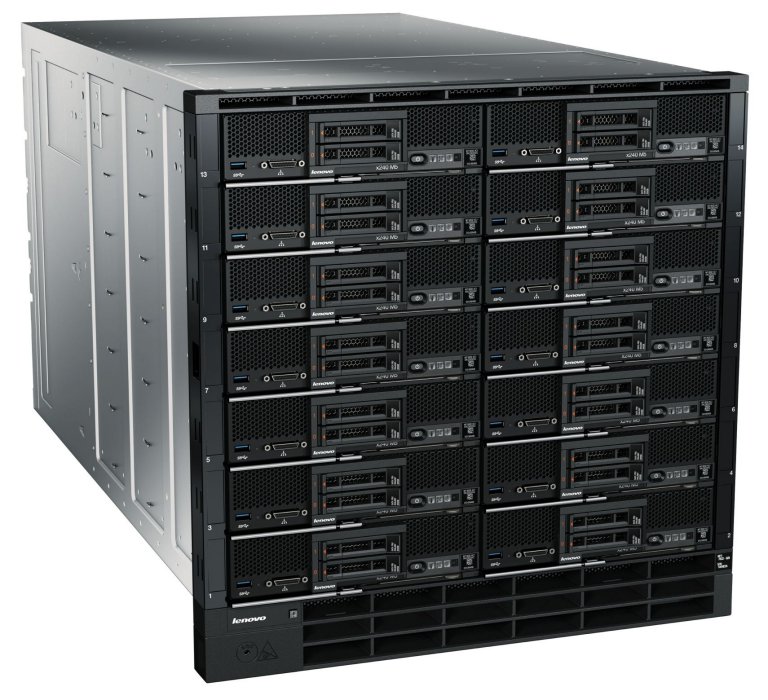
Figure 1. Flex System Carrier-Grade Chassis
Did you know?
The chassis is ASHRAE 4 compliant, meaning it allows normal operation in temperatures of up to 45 °C (113 °F), with temporary elevated temperature excursions of up to 55 °C (131 °F) for as long as 4 days. This is a key requirement for industries, such as the telecommunications industry where the harsher environments in central offices (COs) require IT equipment that operate on -48V DC power and can tolerate higher temperatures.
Key features
Similar to the Enterprise Chassis, the Flex System Carrier-Grade Chassis is a simple, integrated infrastructure platform that supports a mix of compute, storage, and networking resources to meet the demands of your applications. The solution is easily scalable with the addition of another chassis with the required nodes. With Lenovo XClarity Administrator, multiple chassis can be monitored from a single window. This flexible 14 node, 10U chassis is designed for a simple deployment now and to scale to meet your needs in the future.
Flexibility and efficiency
The 14 bays in the chassis allow the installation of compute nodes, with I/O modules in the rear. A single chassis or a group of chassis can be fully customized to the specific needs of the computing environment. IT can meet the needs of the business by using a single system across multiple operating environments.
The system monitors and manages power usage on all major chassis components so you have total control over power consumption. With -48V DC power supplies and N+N or N+1 redundancy, the chassis integrates into telco environments, such as those in central offices. The chassis design also optimizes cooling with cooling zones within the chassis. There is sufficient cooling throughout the chassis to allow normal operation in temperatures of up to 45 °C (113 °F), with temporary elevated temperature excursions of up to 55 °C (131 °F) for as long as 4 days.
The system manages the fan modules based on the node configuration within the chassis. Therefore, the system can increase the speed of certain fan modules to cool potential hot spots and use lower speeds for other fan modules where appropriate.
Easily scalable with simple administration
Because the Carrier-Grade Chassis is an all-in-one solution, it is designed for growth from a single chassis to many. Adding compute or networking capability is as simple as adding nodes or modules. The simple, highly integrated management system allows you to use the Chassis Management Modules that are integrated into each chassis to administer a single chassis, and the new Lenovo XClarity Administrator offers agent-free hardware management for compute nodes and networking.
Designed for multiple generations of technology
The Carrier-Grade Chassis is designed to be the foundation of your IT infrastructure now and into the future. Compute performance requirements are always on the rise and networking demands continue to grow with rising bandwidth needs and a shrinking tolerance for latency. The chassis is designed to scale to meet the needs of your future workloads, and offers the flexibility to support current and future innovations in compute, storage, and networking technology.
Locations of key components and connectors
Figure 2 shows the front of the Carrier-Grade Chassis.
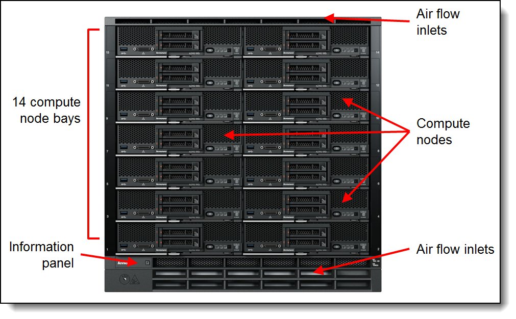
Figure 2. Front of the Flex System Carrier-Grade Chassis
Figure 3 shows the rear of the Carrier-Grade Chassis.
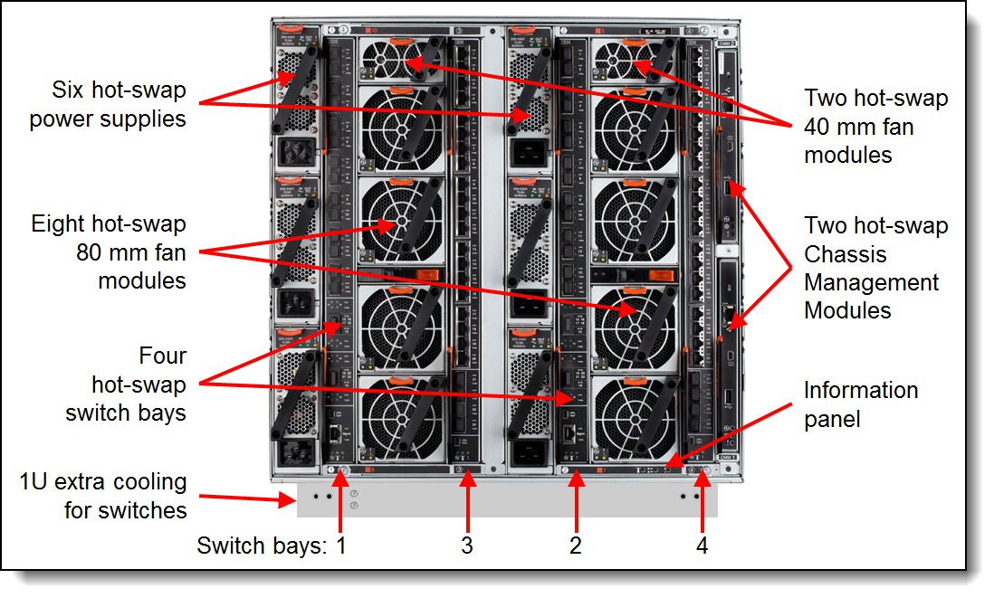
Figure 3. Rear of the Flex System Carrier-Grade Chassis
Standard specifications
The following table lists the standard specifications.
| Components | Specification |
|---|---|
| Machine type-model | 7385-DCx |
| Form factor | 11U rack-mounted unit |
| Compute nodes per chassis | 14 standard-width (half-wide) nodes. |
| Management | One or two CMM2 for chassis management. Two CMM2 form a redundant pair. One CMM2 is standard in 7385-DCx. The CMM2 interfaces with the Integrated Management Module II (IMM2) that is integrated in each compute node within the chassis. Lenovo XClarity Administrator provides comprehensive management that includes virtualization, networking, and storage management. |
| I/O architecture | Up to eight lanes of I/O to an I/O adapter, with each lane capable of up to 16 Gbps bandwidth. Up to 16 lanes of I/O to a half wide-node with two adapters. Various networking solutions include Ethernet, Fibre Channel, and FCoE. |
| Power supplies | Up to six power supplies that can provide N+N or N+1 redundant power. Each power supply contains two independently powered 40 mm cooling fan modules. Two 2500 W -48 V DC power supplies standard with support for up to six power supplies to support a full chassis configuration. |
| Fan modules |
A total of 10 fan modules (eight 80 mm fan modules and two 40 mm fan modules) |
| Telecommunication standards | NEBS Level 3, ETSI (EN 300 386, EN 300 132-2, EN 300 132-3, EN 300 019, and EN 300 753) |
| Earthquake Zone operation | Zone 4 |
| Dimensions |
Height: 483 mm (19.2 in.) (11 EIA rack standard units) |
| Weight |
Fully configured (stand-alone): Approximately 229.2 kg (505.2 lb) |
| Declared sound level | 7.5 bels |
| Temperature | Normal low-altitude operation:
|
| Air filter | Front mounted NEBS-compliant air filter with replaceable filter media |
| Electrical power |
Input voltage: -48v DC Minimum configuration: 0.51 kVA (two power supplies) Maximum configuration: 13 kVA (six 2500 W power supplies) |
| Power usage | 12,900 watts maximum |
The table in the next section lists the included components of each standard model. In addition, each model ships with the following components:
- Rail kit
- Rack installation kit and template
- Chassis handles
- Setup poster
- Product documentation
Models
The following table lists the specifications of the standard models.
Table 2. Models
| Model | Firmware codebase |
Node bays |
CMM (2 max) |
I/O bays (used / max) |
I/O modules included |
Power supplies (6 max) |
40mm fans (2 max) |
80mm fan (8 max) |
Console breakout cable |
| 7385-DCx | Lenovo | 14 | 1x CMM2 | 0 / 4 | None | 2x 2500W -48V DC |
2 | 4 | 1 |
Supported compute nodes
The following table lists the compute nodes that are supported in the Flex System Carrier-Grade Chassis. The table also lists the maximum installable number.
| Description | Machine type |
Supported in chassis |
Maximum supported** |
| Lenovo x86 servers | |||
| Flex System x220 | 7906 | No | None |
| Flex System x222 | 7916 | No | None |
| Flex System x240 | 7162 | No | None |
| Flex System x240 | 8737 | No | None |
| Flex System x240 M5 | 9532 | Supported* | 14 |
| Flex System x440 | 7917 | No | None |
| Flex System x440 | 7167 | No | None |
| Flex System x280 X6 | 7196 | No | None |
| Flex System x480 X6 | 7196 | No | None |
| Flex System x880 X6 | 7196 | No | None |
| Flex System x280 X6 | 7903 | No | None |
| Flex System x480 X6 | 7903 | No | None |
| Flex System x880 X6 | 7903 | No | None |
| IBM Flex System Manager | 8731-A1x | No | None |
| IBM Power Systems servers | |||
| Flex System p24L | 1457 | No | None |
| Flex System p260 | 7895-22X | No | None |
| Flex System p270 | 7954-24X | No | None |
| Flex System p460 | 7895-42X | No | None |
* Specific configurations of these compute nodes are supported in the chassis. For more information, see the section, “Supported compute node configurations”.
** The maximum number of supported compute nodes depends on several factors. For more information, see the section, “Supported numbers of compute nodes”.
Supported compute node configurations
The following table lists the compute node components that are supported when they are installed in the Carrier-Grade chassis and meet the NEBS and ETSI requirements, as listed in Table 1.
| Component | Flex System x240 M5 (9532) |
| Processors (Max 2) |
|
| Memory | All compatible memory options |
| IO Adapters |
|
| Drive enablement kits |
|
| SAS HDD | All compatible 2.5-inch and 1.8-inch SAS/SATA HDD and SSD options PCe NVMe drives not supported |
| VMware Hypervisor | All compatible SD Media options |
| Storage Expansion Node | Not supported |
| PCIe Expansion Node | Not supported |
Supported numbers of compute nodes
The actual number of compute nodes systems that can be powered on in a chassis depends on the following factors:
- The TDP power rating for the processors that are installed in the compute nodes.
- The number of power supplies that are installed in the chassis.
- The power redundancy policy that is used in the chassis (N+1 or N+N).
The table in the Power Supplies section provides guidelines about the number of compute nodes that can be powered on in the chassis based on the type and number of power supplies that are installed.
For information about the supported servers, see this web page:
http://www.lenovo.com/us/en/serverproven/flexsystem.shtml
Supported I/O modules
The Flex System Carrier-Grade Chassis has four high-speed switch bays that can support various I/O architectures.
The switches are installed in switch bays in the rear of the Flex System Carrier-Grade Chassis, as shown in the following figure. Switches are normally installed in pairs (bays 1 and 2, and bays 3 and 4), because I/O adapters that are installed in the compute nodes route to two switch bays for performance and redundancy.
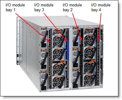
Figure 4. Location of the switch bays in the Flex System Carrier-Grade Chassis
The following table lists the switches that are supported in the Carrier-Grade Chassis in NEBS-compliant mode.
| Description | Part number | Supported in NEBS mode |
|---|---|---|
| Ethernet modules | ||
| EN4093R 10Gb Scalable Switch | 00FM514 | Supported |
| CN4093 10Gb Converged Scalable Switch | 00FM510 | Supported |
| SI4091 10Gb System Interconnect Module | 00FE327 | No |
| SI4093 System Interconnect Module | 00FM518 | No |
| EN2092 1Gb Ethernet Scalable Switch | 49Y4294 | Supported |
| EN4091 10Gb Ethernet Pass-thru | 88Y6043 | No |
| EN4093 10Gb Scalable Switch | 49Y4270 | No |
| EN4093R 10Gb Scalable Switch | 95Y3309 | No |
| CN4093 10Gb Converged Scalable Switch | 00D5823 | No |
| SI4093 System Interconnect Module | 95Y3313 | No |
| Cisco Nexus B22 Fabric Extender | 94Y5350 | No |
| EN4023 10Gb Scalable Switch | 94Y5212 | No |
| EN6131 40Gb Ethernet Switch | 90Y9346 | No |
| Fibre Channel switches | ||
| FC5022 16Gb SAN Scalable Switch | 88Y6374 | Supported |
| FC5022 24-port 16Gb SAN Scalable Switch | 00Y3324 | Supported |
| FC5022 24-port 16Gb ESB SAN Scalable Switch | 90Y9356 | Supported |
| FC3171 8Gb SAN Switch | 69Y1930 | No |
| FC3171 8Gb SAN Pass-thru | 69Y1934 | No |
| InfiniBand switches | ||
| IB6131 InfiniBand Switch (QDR/FDR) | 90Y3450 | No |
I/O architecture
Each half-wide compute node (such as the Flex System x240 M5 Compute Node) has two adapter slots. The adapter slots in each compute node route through the chassis midplane to the switch bays. The architecture supports up to eight ports per adapter. The following figure shows how two-port adapters are connected to switches that are installed in the chassis.
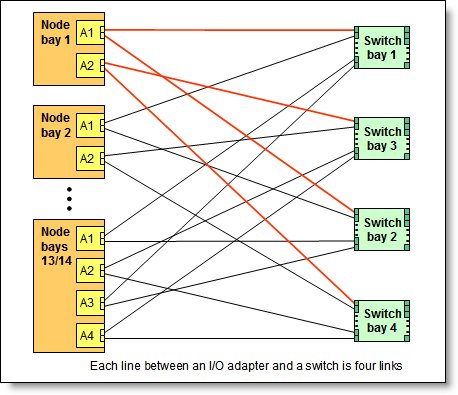
Figure 5. Logical layout of the interconnects between two-port I/O adapters and I/O modules
A four-port adapter doubles the connections between each adapter and switch pair (for example, a four-port adapter in A1 in each compute node routes two connections to switch 1 and two connections to switch 2).
The following figure shows how four-port adapters are connected to switches that are installed in the chassis.
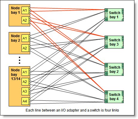
Figure 6. Logical layout of the inter-connections between four-port I/O adapters and I/O modules
The following table lists the connections between the adapter slots in the compute nodes to the switch bays in the chassis.
Table 6. Adapter to I/O bay correspondence
| I/O adapter slot in the server |
Port on the adapter | Corresponding I/O module bay in the chassis |
| Slot 1 | Port 1 | Module bay 1 |
| Port 2 | Module bay 2 | |
| Port 3 (for 4-port cards)* | Module bay 1 | |
| Port 4 (for 4-port cards)* | Module bay 2 | |
| Slot 2 | Port 1 | Module bay 3 |
| Port 2 | Module bay 4 | |
| Port 3 (for 4-port cards)* | Module bay 3 | |
| Port 4 (for 4-port cards)* | Module bay 4 | |
| Slot 3 (full-wide compute nodes only) |
Port 1 | Module bay 1 |
| Port 2 | Module bay 2 | |
| Port 3 (for 4-port cards)* | Module bay 1 | |
| Port 4 (for 4-port cards)* | Module bay 2 | |
| Slot 4 (full-wide compute nodes only) |
Port 1 | Module bay 3 |
| Port 2 | Module bay 4 | |
| Port 3 (for 4-port cards)* | Module bay 3 | |
| Port 4 (for 4-port cards)* | Module bay 4 |
* To make use of all four ports of a four-port adapter, the switch must have 28 internal ports enabled and two switches must be installed in the bays, as indicated.
Chassis Management Module
The Chassis Management Module 2 (CMM2) provides single-chassis management in the Carrier-Grade Chassis. The CMM is used to communicate with the integrated management module (IMM) controller in each compute node to provide system monitoring, event recording and alerts, and to manage the chassis, its devices, and the compute nodes.
The chassis has one CMM installed standard but supports two CMMs for redundancy. If one CMM fails, the second CMM can detect its inactivity and activate to take control of the system without any disruption. The CMM is central to the management of the chassis and is required in the Carrier-Grade Chassis.
The following table shows the ordering information.
Table 7. Chassis Management Module
| Part number |
Feature codes* | Description | Standard / Maximum |
| 00FJ669 | ASPT / ASQ8 | Flex System Chassis Management Module 2 | 1 / 2 |
* The first feature code corresponds to the base CMM installed in the chassis. The second feature code corresponds to the optional second CMM which provides redundancy.
The following figure shows the CMM. For more information about the location of the CMM in the chassis, see Figure 3.
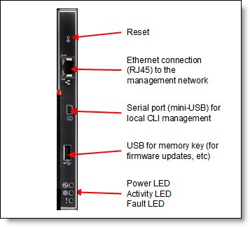
Figure 7. Chassis Management Module
The CMM provides the following functions:
- Power control
- Fan management
- Chassis and compute node initialization
- Switch management
- Chassis, I/O options, and compute nodes diagnostics
- Resource discovery and inventory management
- Resource alerts and monitoring management
- Chassis and compute node power management
- Security policy management
- Role-based access control
- Support for up to 84 local CMM user accounts
- Support for up to 32 simultaneous sessions
The CMM has the following connectors:
- USB connection. This connection can be used for insertion of a USB media key for tasks, such as firmware updates.
- 10/100/1000 Mbps RJ45 Ethernet connection to connect to a management network. The CMM can be managed via this Ethernet port.
- Serial port (mini-USB) for local command-line interface (CLI) management. Use serial cable 90Y9338 for connectivity.
The CMM features light-emitting diodes (LEDs) that provide the following information:
- Power-on LED
- Activity LED
- Error LED
- Ethernet port link and port activity LEDs
The CMM also incorporates a reset button, which resets the CMM to its default condition when pressed. It has the following functions, depending on how long the button is pressed:
- When the button is pressed for less than 5 seconds, the CMM restarts.
- When the button pressed for more than 5 seconds, the CMM configuration is reset to the manufacturing defaults and the CMM restarts.
The CMM supports a web-based graphical user interface (GUI) with which CMM functions can be performed within a supported web browser. You can also perform management functions through the CMM CLI. The web-based GUI and the CLI are accessible via the single RJ45 Ethernet connector on the CMM or from any other system that is connected to the same (management) network.
The CMM has the following default static IPv4 address. By default, the CMM is configured to respond to Dynamic Host Configuration Protocol (DHCP) first before its static IPv4 address is used:
- IP address: 192.168.70.100
- Subnet: 255.255.255.0
- User ID: USERID (all capital letters)
- Password: PASSW0RD (all capital letters, with a zero instead of the letter O)
The CMM does not have a fixed static IPv6 IP address by default. Initial access to the CMM in an IPv6 environment can be performed by using the IPv4 IP address or the IPv6 link-local address. The IPv6 link-local address is automatically generated based on the Media Access Control (MAC) address of the CMM.
The CMM is the key component that enables the integrated management network. Internally, the CMM has a multiple port L2 1Gigabit Ethernet switch with dedicated links to all 14 node bays, all four switch bays, and the second CMM, if installed. These connections are all point-to-point, which ensures dedicated bandwidth. The 1GbE links are full-duplex, fixed speed (not auto-negotiate) links. The 1 GbE management network is accessible only by each node's management controller, each switch module's management interfaces, and the CMM. This design permits the separation of the management network from the data network.
The CMM has a high-security policy that is enabled by default, which means that the following policies are enabled by default:
- Strong password policies with automatic validation and verification checks.
- Required update of the default passwords after the initial setup.
- Only secure communication protocols, such as SSH and SSL. Unencrypted protocols, such as HTTP, Telnet, and SNMPv1, are disabled.
- Certificates to establish secure, trusted connections for applications that run on the management processors.
Lenovo XClarity Administrator
Lenovo XClarity Administrator is centralized resource management solution that is aimed at reducing complexity, speeding response, and enhancing availability of Lenovo server systems and solutions.
Lenovo XClarity Administrator provides agent-free hardware management for System x rack servers and Flex System compute nodes and components, including the CMM and Flex System I/O modules. The following figure shows the Lenovo XClarity Administrator interface in which both Flex System components and rack servers are managed and can be seen on the dashboard.
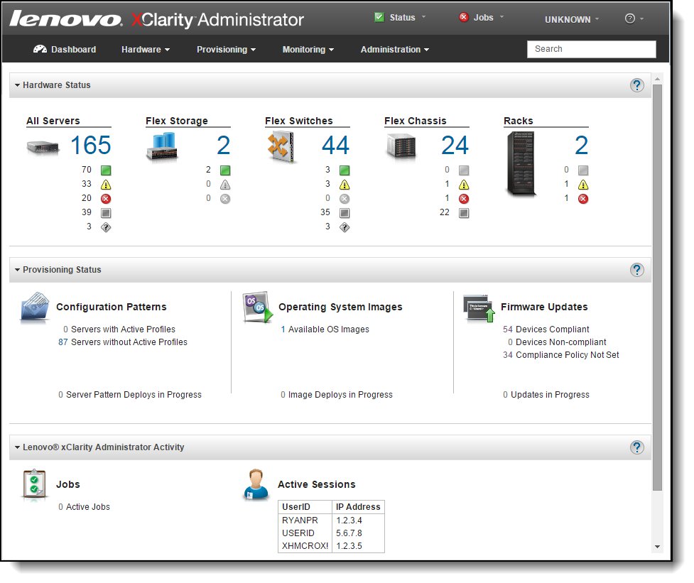
Figure 8. Lenovo XClarity Administrator dashboard
For information about Lenovo XClarity Administrator, see the Lenovo Press Product Guide that is available at this website:
http://lenovopress.com/tips1200
Power supplies
A maximum of six power supplies can be installed in the Carrier-Grade Chassis. The chassis currently supports the -48V DC power supply option. Model DCx has two power supplies standard. The ordering part number and feature code is listed in the following table.
Table 8. Ordering part number and feature code
| Description | Part number | Feature code | Standard / Max |
| Flex System Enterprise Chassis -48V DC 2500W Power Module | 00FJ635 | A5VC | 2 / 6 |
The -48V DC power supply operates at -48V to -60 V dc (nominal) and has a Molex 1060 Power Connector. The power supply ships with one 2.0m DC power cord (FRU part number 69Y1652)
The chassis allows configurations of power supplies to give N+N or N+1 redundancy. Although a chassis can operate on only three power-supply units (PSUs) with no redundancy, N+1 or N+N is advised. Three power supplies (or six with N+N redundancy) allow for a balanced three-phase configuration.
All power supply modules are combined into a single power domain within the chassis, which distributes power to each of the compute nodes, I/O modules, and ancillary components through the Carrier-Grade Chassis midplane. The midplane is a highly reliable design with no active components. Each power supply is designed to provide fault isolation and is hot swappable.
The following figure shows the compute node bay numbering (left) and power supply bay numbering (right).
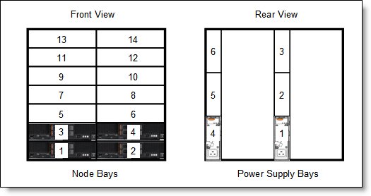
Figure 9. Power supply bay numbering
The following table shows the number of compute nodes that are supported in the chassis based on the number of power supplies that are installed and the power redundancy policy that is enabled (N+1 or N+N).
In this table, the colors of the cells have the following meaning:
- Green cell: Supported with no restrictions as to the number of compute nodes that can be installed
- Yellow cell: Supported but with restrictions on the number of compute nodes that can be installed.
Note: These tables assume the chassis includes identical compute nodes. For more complex configurations, use the Power Configurator that is available at this web page:
https://ibm.com/support/entry/portal/docdisplay?lndocid=LNVO-PWRCONF
| CPU TDP |
N+1, N=5 6 total |
N+1, N=4 5 total |
N+1, N=3 4 total |
N+N, N=3 6 total |
| Flex System x240 | ||||
| 60 W | 14 | 14 | 14 | 14 |
| 70 W | 14 | 14 | 14 | 14 |
| 80 W | 14 | 14 | 14 | 14 |
| 95 W | 14 | 14 | 14 | 14 |
| 115 W | 14 | 14 | 14 | 14 |
| 130 W | 14 | 14 | 13 | 14 |
| 135 W | 14 | 14 | 13 | 14 |
| Flex System x240 M5 | ||||
| 52 W | 14 | 14 | 14 | 14 |
| 55 W | 14 | 14 | 14 | 14 |
| 65 W | 14 | 14 | 14 | 14 |
| 75 W | 14 | 14 | 14 | 14 |
| 85 W | 14 | 14 | 14 | 14 |
| 90 W | 14 | 14 | 14 | 14 |
| 105 W | 14 | 14 | 13 | 14 |
| 120 W | 14 | 14 | 13 | 14 |
| 135 W | 14 | 14 | 12 | 13 |
| 145 W | 14 | 14 | 12 | 13 |
Fan modules
The Carrier-Grade Chassis supports up to a total of 10 hot-swap fan modules: two 40 mm (1.57 in) fan modules and eight 80 mm (3.14 in) fan modules.
The two 40 mm fan modules (which ship with the chassis) distribute airflow to the I/O modules and CMMs. The 80 mm fan modules distribute airflow to the compute nodes through the chassis from front to rear. Each 80 mm fan module contains two 80 mm fan modules, back-to-back at each end of the module, which are counter-rotating. The following figure shows the 80 mm fan module.
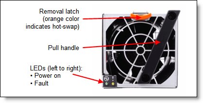
Figure 10. 80 mm fan module
Four 80 mm fan modules are installed standard in the DCx chassis model. The maximum number of 80 mm fan modules that can be installed is eight. Ordering information is shown in the following table. When the modules are ordered as a part number, they are supplied as a pair. The feature codes include one fan.
| Description | Part number | Feature code |
| Flex System Enterprise Chassis 80mm Fan Module | 43W9078 (2 fan modules) |
A0UA (1 fan module) |
The 80 mm fan modules are populated, depending on the nodes installed. To support the base configuration and up to four nodes, the standard model ships with four 80 mm fan modules and two 40 mm fan modules preinstalled. There are separate left and right cooling zones for the nodes. Fan modules must be installed in pairs, as shown in the following figure. If there are insufficient fan modules for the number of nodes installed, the compute nodes might be throttled to balance heat generation and cooling capacity.
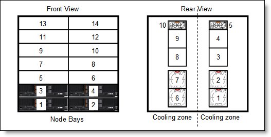
Figure 11. Fan module locations and cooling zones
The 40 mm fan modules are always required. Extra 80 mm fan modules are required, as listed in the following table.
Table 11. 80 mm fan module requirements
| Description | 80 mm fan module requirements |
| Up to four half-wide compute nodes (node bays 1 - 4) | 4 fan modules (fan bays 1, 2, and 6, 7) |
| Up to eight half-wide compute nodes (node bays 1 - 8) | 6 fan modules (fan bays 1, 2, 3 and 6, 7, 8) |
| All 14 compute node bays (node bays 1 - 14) | 8 fan modules (fan bays 1, 2, 3, 4 and 6, 7, 8, 9) |
Air filters
The Carrier-Grade Chassis includes an airborne contaminate filter that is fitted to the front of the chassis in two components. The main filter assembly covers the compute nodes and a secondary filter assembly covers the 1U air-inlet at the bottom of the chassis.
Each filter assembly includes 6 mm polyurethane filter media that should be removed, inspected, and replaced on a regular basis. The filter media pieces are usable parts and are not covered under the terms of the warranty. Lenovo recommends the following service intervals:
- For low dust, low foot traffic environments, inspect and clean the filter media every 3 months and replace the filter media every 6 months.
- For moderate dust, moderate foot traffic environments, inspect and clean the filter media every 6 weeks and replace the filter media every 3 months.
- For heavy dust, heavy foot traffic environments, inspect and clean the filter media every 2 weeks and replace the filter media every 1 month.
Table 12. Filter media replacement part
| Part number | Feature code | Description |
| 43W9057 | A2AU | Flex System airborne contaminant filter replacement pack (contains four sets of filter media replacements) |
Physical specifications
The chassis includes the following specifications:
- Dimensions:
- Height: 483 mm (19.2 in.) (11 EIA rack standard units)
- Width: 447 mm (17.6 in.) (EIA 19-inch rack standard width)
- Depth: 854 mm (33.6 in.)
- Weight (approximate):
- Fully configured (stand-alone): 229.2 kg (505.2 lb)
- Fully configured (in the rack): 234.3 kg (516.5 lb)
- Empty chassis with shelves: 70.4 kg (155.3 lb)
- Empty chassis without shelves: 48.9 kg (107.9 lb)
- Shipping:
- Height: 957 mm
- Length: 1016 mm
- Width: 610 mm
- Weight: 187.5 kg
Supported environment
Flex System Carrier-Grade Chassis that are equipped with -48 V dc power supplies are NEBS level 3 certified.
The Chassis is supported in the following environment:
- Operating, low altitude:
- Relative humidity 5% - 85% (See Note 1)
- Temperature 5 °C to 45 °C (41 °F - 113 °F) (See Note 2)
- Maximum altitude 1829 m (6,000 ft)
- Maximum rate of temperature change 30 °C/hr (80 °F/hr) (See Note 3)
- Operating, high altitude (includes fan failure):
- Relative humidity 5% - 85% (See Note 1)
- Temperature 5 °C - 45 °C (41 °F - 113 °F) (See Note 2)
- Altitude range 1829 - 3960 m (6,000 - 13,000 ft)
- Maximum rate of temperature change 30 °C/hr (80 °F/hr) (See Note 3)
- Operating, short-term excursions (room HVAC failure) (See Note 5):
- Relative humidity 5% - 93% (See Note 1)
- Temperature 5 °C to 55 °C (41 °F - 131 °F) (See Note 2)
- Maximum altitude 1829 m (6,000 ft)
- Non-operating, storage: (See Note 4):
- Relative humidity 5% - 80% (See Note 1)
- Temperature 1 °C - 70 °C (33.8 °F - 158 °F)
- Altitude 3050 m (10,006 ft)
- Non-operating, shipment (See Note 4):
- Relative humidity 5% - 100% (See Note 1)
- Temperature -40 °C - 70 °C (-40 °F - 158 °F)
- Altitude 10,700 m (35,105 ft)
Notes:
- Water-to-air ratio must never exceed 0.026 kg H20 per kg dry air.
- Derate maximum allowable temperature 1 °C/213 m above 1829 m. This maximum temperature is for a self-standing system that is not in a rack. If in a rack, deduct 5 °C.
- The 30 °C/hr rate is for data centers that use disk drives; tape drives are not used.
- The equipment acclimation period is 1 hour per 30 °C of temperature change from the shipping or storage environment to the operating environment.
- One excursion is defined at no more than four days (96 hrs); all excursions per year should not exceed 15 days (360 hrs).
Electrical, therman and noise specifications:
- Electrical power (-48 V dc 2500 W Power Modules):
- -48 V to -60 V dc (nominal)
- Minimum configuration: 0.51 kVA (two power supplies)
- Maximum configuration: 13 kVA (six power supplies)
- Power consumption: 12,900 watts (maximum)
- Thermal output:
- Ship configuration: 500 watts (1,700 Btu/hr)
- Full configuration: 12,900 watts (43,900 Btu/hr)
- Acoustical noise emissions for Flex Chassis:
- 7.5 bels operating
- 7.5 bels idling
The noise emission level that is listed is the declared (upper limit) sound power level (in bels) for a random sample of machines. All measurements are made in accordance with ISO 7779 and reported in conformance with ISO 9296.
Warranty options
The Flex System Carrier-Grade Chassis has a three-year warranty with 24x7 standard call center support and 9x5 Next Business Day onsite coverage. Also available are Lenovo Services warranty maintenance upgrades and post-warranty maintenance agreements, with a well-defined scope of services, including service hours, response time, term of service, and service agreement terms and conditions.
Lenovo warranty service upgrade offerings are country-specific. Not all warranty service upgrades are available in every country. For more information about Lenovo warranty service upgrade offerings that are available in your country, to to the Lenovo configurator at http://lesc.lenovo.com.
The following table lists the warranty service definitions.
Table 13. Warranty service definitions
| Term | Description |
| On-site service | A service technician arrives at the client’s location for equipment service. |
| 24x7x2 hour | A service technician is scheduled to arrive at the client’s location within two hours after remote problem determination is completed. Lenovo provides service around the clock, every day, including Lenovo holidays. |
| 24x7x4 hour | A service technician is scheduled to arrive at the client’s location within four hours after remote problem determination is completed. Lenovo provides service around the clock, every day, including Lenovo holidays. |
| 9x5x4 hour | A service technician is scheduled to arrive at the client’s location within four business hours after remote problem determination is completed. Lenovo provides service 8:00 am - 5:00 pm in the client's local time zone, Monday-Friday, excluding Lenovo holidays. For example, if a customer reports an incident at 3:00 pm on Friday, the technician will arrive by 10:00 am the following Monday. |
| 9x5 next business day | A service technician is scheduled to arrive at the client’s location on the business day after remote problem determination is completed. Lenovo provides service 8:00 am - 5:00 pm in the client's local time zone, Monday - Friday, excluding Lenovo holidays. Calls received after 4:00 pm local time require an extra business day for service dispatch. Next business day service is not guaranteed. |
| Committed Repair | Problems receive priority handling so that repairs are completed within the committed time of 6, 8, or 24 hours. Lenovo provides service 24 hours/day, every day, including Lenovo holidays. |
The following Lenovo warranty service upgrades are available:
- Warranty and maintenance service upgrades:
- Three, four, or five years of 9x5 or 24x7 service coverage
- Onsite response from next business day to 2 or 4 hours
- Committed repair service
- Warranty extension of up to 5 years
- Post warranty extensions
- Committed Repair Service
Committed Repair Services enhances the level of Warranty Service Upgrade or Post Warranty/Maintenance Service offering associated with the selected systems. Offerings vary and are available in select countries.
- Priority handling to meet defined time frames to restore the failing machine to good working condition
- Committed repair service levels are measured within the following coverage hours:
- 24x7x6: Service performed 24 hours per day, 7 days per week, within 6 hours
- 24x7x8: Service performed 24 hours per day, 7 days per week, within 8 hours
- 24x7x24: Service performed 24 hours per day, 7 days per week, within 24 hours
- Hard Drive Retention
Lenovo’s Hard Drive Retention service is a multi-drive hard drive retention offering that ensures your data is always under your control, regardless of the number of hard drives that are installed in your Lenovo server. In the unlikely event of a hard drive failure, you retain possession of your hard drive while Lenovo replaces the failed drive part. Your data stays safely on your premises, in your hands. The Hard Drive Retention service can be purchased in convenient bundles with our warranty upgrades and extensions.
- Microcode Support
Keeping microcode current helps prevent hardware failures and security exposure. There are two levels of service: Analysis of the installed base and analysis and update where required. Offerings vary by country and can be bundled with other warranty upgrades and extensions.
- Remote Technical Support Services (RTS)
RTS provides comprehensive technical call center support for covered servers, storage, operating systems, and applications. Providing a single source for support of hardware and software issues, RTS can reduce problem resolution time, which decreases the cost to address technical problems and increases uptime. Offerings are available for Windows, Linux, IBM Systems Director, VMware, Microsoft business applications, and Lenovo System x storage devices, and IBM OEM storage devices.
Regulatory compliance
The server conforms to the following standards:
- NEBS Level 3
- ETSI EN 300 386
- ETSI EN 300 132-2
- ETSI EN 300 132-3
- ETSI EN 300 019
- ETSI EN 300 753
- ASHRAE Class A4
- FCC - Verified to comply with Part 15 of the FCC Rules Class A
- Canada ICES-004, issue 3 Class A
- UL/IEC 60950-1
- CSA C22.2 No. 60950-1
- NOM-019
- Argentina IEC 60950-1
- Japan VCCI, Class A
- IEC 60950-1 (CB Certificate and CB Test Report)
- Taiwan BSMI CNS13438, Class A
- Australia/New Zealand AS/NZS CISPR 22, Class A
- Korea KN22, Class A, KN24
- EAC Custom Union
- IEC 60950-1 (CB Certificate and CB Test Report)
- CE Mark (EN55022 Class A, EN60950-1, EN55024, EN61000-3-2, EN61000-3-3)
- CISPR 22, Class A
- TUV-GS (EN60950-1/IEC 60950-1, EK1-ITB2000)
Trademarks
Lenovo and the Lenovo logo are trademarks or registered trademarks of Lenovo in the United States, other countries, or both. A current list of Lenovo trademarks is available on the Web at https://www.lenovo.com/us/en/legal/copytrade/.
The following terms are trademarks of Lenovo in the United States, other countries, or both:
Lenovo®
Flex System
Lenovo Services
ServeRAID
ServerProven®
System x®
XClarity®
The following terms are trademarks of other companies:
Linux® is the trademark of Linus Torvalds in the U.S. and other countries.
Microsoft® and Windows® are trademarks of Microsoft Corporation in the United States, other countries, or both.
Other company, product, or service names may be trademarks or service marks of others.


