

Top
Abstract
The Flex System™ PCIe Expansion Node provides the ability to attach additional PCI Express cards, such as High IOPS SSD adapters, fabric mezzanine cards, and next-generation graphics processing units (GPU), to supported Flex System compute nodes. This capability is ideal for many applications that require high performance I/O, special telecommunications network interfaces, or hardware acceleration using a PCI Express GPU card. The PCIe Expansion Node supports up to four PCIe adapters and two additional Flex System I/O expansion adapters.
Change History
Changes in the February 4 update:
- The PCIe Expansion Node is now withdrawn from marketing
- Marked withdrawn adapters
Introduction
The Flex System™ PCIe Expansion Node provides the ability to attach additional PCI Express cards, such as High IOPS SSD adapters, fabric mezzanine cards, and next-generation graphics processing units (GPU), to supported Flex System compute nodes. This capability is ideal for many applications that require high performance I/O, special telecommunications network interfaces, or hardware acceleration using a PCI Express GPU card. The PCIe Expansion Node supports up to four PCIe adapters and two additional Flex System I/O expansion adapters.
Figure 1 shows the Flex System PCIe Expansion Node attached to a Flex System x240 Compute Node.
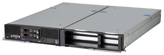
Figure 1. Flex System PCIe Expansion Node (right) attached to an x240 Compute Node (left)
Did you know?
The PCIe Expansion Node is ideal for application environments that are written to take advantage of acceleration and visualization performance using GPUs that are connected to Flex System Compute nodes. It is also useful for environments that require specific PCIe adapter connectivity to a Flex System Compute node.
Part number information
Table 1. Ordering part number and feature code
| Description | Part number | Feature code |
| Flex System PCIe Expansion Node | 81Y8983 | A1BV |
The part number includes the following items:
- Flex System PCIe Expansion Node
- Two riser assemblies
- Interposer cable assembly
- Double-wide shelf
- Two auxiliary power cables (for adapters that require additional +12V power)
- Four removable PCIe slot air flow baffles
- Documentation package
Supported servers
The Flex System PCIe Expansion Node is supported when it is attached to the Flex System compute nodes listed in Table 2. Only one Expansion Node can be attached to each compute node.
| Part number | Description |
x220 (7906)
|
x222 (7916)
|
x240 (8737, E5-2600)
|
x240 (8737, E5-2600 v2)
|
x240 (7162)
|
x240 M5 (9532)
|
x240 M5 NEBS
|
x440 (7917)
|
x440 (7167)
|
x880/x480/x280 X6 (7903)
|
x280/x480/x880 X6 (7196)
|
|---|---|---|---|---|---|---|---|---|---|---|---|---|
| 81Y8983 | PCIe Expansion Node | Y* | N | Y* | Y* | Y* | Y*† | N | N | N | N | N |
* The PCIe Expansion Node requires that both processors be installed in the compute node.
† Support for the x240 M5 with NVIDA adapters only when the compute node has 1 TB or less of memory installed.
Features
The PCIe Expansion Node has the following features:
- Support for up to four standard PCIe 2.0 adapters:
- Two PCIe 2.0 x16 slots that support full-length, full-height adapters (1x, 2x, 4x, 8x, and 16x adapters supported)
- Two PCIe 2.0 x8 slots that support low-profile adapters (1x, 2x, 4x, and 8x adapters supported)
- Support for PCIe 3.0 adapters by operating them in PCIe 2.0 mode
- Support for one full-length, full-height double-wide adapter (consuming the space of the two full-length, full-height adapter slots)
- Support for PCIe cards with higher power requirements
The Expansion Node provides two auxiliary power connections, up to 75W each for a total of 150W of additional power using standard 2x3, +12V six-pin power connectors. These connectors are placed on the base planar so that they both can provide power to a single adapter card (up to 225W), or to two adapters (up to 150W each). Power cables are used to connect from these connectors to the PCIe adapters and are included with the PCIe Expansion Node.
- Two Flex System I/O expansion connectors
The I/O expansion connectors are labeled I/O expansion 3 connector and I/O expansion 4 connector in Figure 2. These I/O connectors expand the I/O capability of the attached compute node.
The layout of the PCIe Expansion Node is shown in Figure 2. The four PCIe slots are routed through two riser connectors on the system planar.
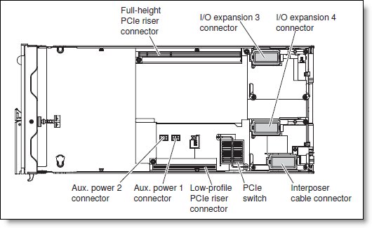
Figure 2. Layout of the PCIe Expansion Node
Figure 3 shows a top-down view of the PCIe Expansion Node connected to the x240 Compute Node.
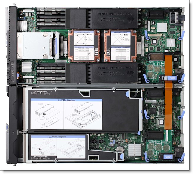
Figure 3. Open view of the PCIe Expansion Node (bottom) connected to the x240 Compute Node (top).
For additional views of the PCIe Expansion Node attached to an x240 M5, see the Flex System x240 M5 Interactive 3D Tour, available from:
https://lenovopress.com/lp0447-flex-system-x240-m5-interactive-3d-tour
Architecture
Figure 4 shows the architecture of the PCIe Expansion Node when connected to a compute node.
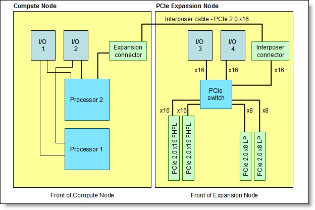
Figure 4. Architecture of the PCIe Expansion Node
The Expansion Node connects to a standard-width compute node using the interposer cable which plugs into the expansion connector and interposer connector on the compute node and Expansion Node respectively. This link forms a PCIe 2.0 x16 connection between the compute node and the PCIe switch in the Expansion Node. The PCIe switch has connections to the six PCIe slots in the Expansion Node:
- PCIe 2.0 x16 connections to the two full-length full-height PCIe slots
- PCIe 2.0 x8 connections to the two low-profile PCIe slots
- PCIe 2.0 x16 connectors to the two Flex System I/O expansion slots (labeled I/O 3 and I/O 4 in the figure).
Notes:
- In compute nodes, such as the x220 and x240, I/O expansion slot 1 and 2 in the server operate at PCIe 3.0 speeds. However, I/O expansion slots 3 and 4 in the PCIe Expansion Node (and also the four standard PCIe slots) operate at PCIe 2.0 speeds.
- The expansion connector in the compute node is routed through processor 2. Therefore, processor 2 must be installed in the compute node.
When adapters are installed in the two I/O expansion slots, they connect to the chassis midplane and provide additional connections to I/O module bays in the chassis. Table 3 shows the connections between the expansion slots and the module bays. Note that the ports available from the adapter vary, depending on whether the adapter is a 2-port or 4-port adapter. Similarly, the number of ports to the I/O module depend on the number of ports activated in the switch.
Table 3. Adapter-to-I/O bay correspondence
| I/O expansion slot | Port on the adapter | Corresponding I/O module bay in the chassis |
| Slot 1 (Compute Node) |
Port 1 | Module bay 1 |
| Port 2 | Module bay 2 | |
| Port 3* | Module bay 1** | |
| Port 4* | Module bay 2** | |
| Slot 2 (Compute Node) |
Port 1 | Module bay 3 |
| Port 2 | Module bay 4 | |
| Port 3* | Module bay 3** | |
| Port 4* | Module bay 4** | |
| Slot 3 (Expansion Node) |
Port 1 | Module bay 1 |
| Port 2 | Module bay 2 | |
| Port 3* | Module bay 1** | |
| Port 4* | Module bay 2** | |
| Slot 4 (Expansion Node) |
Port 1 | Module bay 3 |
| Port 2 | Module bay 4 | |
| Port 3* | Module bay 3** | |
| Port 4* | Module bay 4** |
* Ports 3 and 4 require that a four-port card be installed in the expansion slot.
** Might require one or more port upgrades to be installed in the I/O module.
Supported PCIe adapter cards
The Expansion Node supports the following general adapter characteristics:
- Full-height cards, 4.2 in (107 mm)
- Low-profile cards, 2.5 in (64 mm)
- Half-length cards, 6.6 in (168 mm)
- Full-length cards, 12.3 in (312 mm)
- Support for up to four low-profile PCIe cards
- Support for up to two full-height PCIe cards
- Support for up to one full-height double-wide PCIe card
- Support for PCIe standards 1.1 and 2.0 (PCIe 3.0 adapters supported operating in PCIe 2.0)
The front-facing bezel of the Expansion Node is inset from the normal face of the compute nodes. This inset is to allow for the use of cables connected to PCIe adapter cards that support external connectivity. The Expansion Node provides up to 80 mm of space in the front of the PCIe adapter cards to allow for the bend radius of these cables.
The following table lists the PCIe adapters that are supported in the Expansion Node. Some adapters must be installed in one of the full-height slots as noted. If the NVIDIA Tesla M2090 is installed in the Expansion Node, then an adapter cannot be installed in the other full-height slot. The low-profile slots and Flex System I/O expansion slots can still be used, however.
Note: If an NVIDIA adapter is installed, the maximum system memory that can be installed is 1 TB. See https://support.lenovo.com/us/en/solutions/HT114952 for details.
| Part number |
Feature code |
Description | Maximum Supported |
x220 (7906)
|
x240 (8737, E5-2600)
|
x240 (8737, E5-2600 v2)
|
x240 (7162)
|
x240 M5 (9532, E5-2600 v3)
|
x240 M5 (9532, E5-2600 v4)
|
|---|---|---|---|---|---|---|---|---|---|
| Flash Storage Adapters | |||||||||
| 00YA800* | AT7N | io3 1.25TB Enterprise Mainstream Flash Adapter | 4 | N | N | N | N | Y | Y |
| 00YA803* | AT7P | io3 1.6TB Enterprise Mainstream Flash Adapter | 4 | N | N | N | N | Y | Y |
| 00YA806* | AT7Q | io3 3.2TB Enterprise Mainstream Flash Adapter | 4 | N | N | N | N | Y | Y |
| 00YA809* | AT7R | io3 6.4TB Enterprise Mainstream Flash Adapter | 2 | N | N | N | N | Y | Y |
| 00YA812* | AT7L | Intel P3700 1.6TB NVMe Enterprise Performance Flash Adapter | 4 | N | N | N | N | Y | Y |
| 00YA815* | AT7M | Intel P3700 2.0TB NVMe Enterprise Performance Flash Adapter | 4 | N | N | N | N | Y | Y |
| 00AE995* | ARYP | 1000GB Enterprise io3 Flash Adapter | 4 | N | Y | Y | Y | Y | Y |
| 00AE998* | ARYQ | 1300GB Enterprise io3 Flash Adapter | 4 | N | Y | Y | Y | Y | Y |
| 00JY001* | ARYR | 2600GB Enterprise io3 Flash Adapter | 4 | N | Y | Y | Y | Y | Y |
| 00JY004* | ARYS | 5200GB Enterprise io3 Flash Adapter | 2 | N | Y | Y | Y | Y | Y |
| GPUs | |||||||||
| 47C2137* | A5HD | NVIDIA Tesla K40 for Flex System PCIe Expansion Node | 1†‡ | Y | Y | Y | Y | Y | Y |
| 7C57A02891 | AX8L | NVIDIA Tesla M10 GPU, PCIe (passive) | 1‡ | N | N | N | N | N | Y |
* Withdrawn from marketing
† If this adapter is installed in the Expansion Node, then another adapter cannot be installed in the other full-height slot. The low-profile slots and Flex System I/O expansion slots can still be used
‡ NVIDIA adapters supported only in servers with 1 TB or less memory installed
Consult the ServerProven® site for the current list of adapter cards that are supported in the Expansion Node:
http://www.lenovo.com/us/en/serverproven/flexsystem.shtml
For information about the Flash Storage Adapters, see the list of Internal Storage Product Guides from Lenovo:
https://lenovopress.com/servers/options/ssdadapter
Note: Although the design of Expansion Node allows for a much greater set of standard PCIe adapter cards, the preceding table lists the adapters that are specifically supported. If the PCI Express adapter that you require is not on the ServerProven web site, use the ServerProven Opportunity Request for Evaluation (SPORE) process to confirm compatibility in the desired configuration.
Supported I/O expansion cards
The following table lists the Flex System I/O expansion cards that are supported in the PCIe Expansion Node.
| Part number | Feature code | Description | Supported in PEN |
|---|---|---|---|
| Converged Network adapters | |||
| 88Y5920* | A4K3 | CN4022 2-port 10Gb Converged Adapter | Yes |
| 00JY800* | A5RP | CN4052 2-port 10Gb Virtual Fabric | Yes |
| 00AG540 | ATBT | CN4052S 2-port 10Gb Virtual Fabric Adapter | Yes** |
| 00JY804 | A5RV | CN4052 Virtual Fabric Adapter SW Upgrade (FoD) | Yes |
| 00AG590 | ATBS | CN4054S 4-port 10Gb Virtual Fabric Adapter | Yes** |
| 90Y3558* | A1R0 | CN4054 Virtual Fabric Adapter SW Upgrade (FoD) | Yes |
| 94Y5160* | A4R6 | CN4058S 8-port 10Gb Virtual Fabric | Yes |
| 94Y5164 | A4R9 | CN4058S Virtual Fabric Adapter SW Upgrade (FoD) | Yes |
| Ethernet adapters | |||
| 49Y7900* | A10Y | EN2024 4-port 1Gb Ethernet Adapter | Yes |
| 90Y3466* | A1QY | EN4132 2-port 10 Gb Ethernet Adapter | Yes** |
| 00AG530 | A5RN | EN4172 2-port 10Gb Ethernet Adapter | Yes |
| 90Y3482* | A3HK | EN6132 2-port 40Gb Ethernet Adapter | No |
| Fibre Channel adapters | |||
| 69Y1938 | A1BM | FC3172 2-port 8Gb FC Adapter | Yes |
| 95Y2375* | A2N5 | FC3052 2-port 8Gb FC Adapter | Yes |
| 88Y6370* | A1BP | FC5022 2-port 16Gb FC Adapter | Yes |
| 95Y2379* | A3HU | FC5024D 4-port 16Gb FC Adapter | No |
| 95Y2386* | A45R | FC5052 2-port 16Gb FC Adapter | Yes |
| 95Y2391 | A45S | FC5054 4-port 16Gb FC Adapter | Yes |
| 69Y1942* | A1BQ | FC5172 2-port 16Gb FC Adapter | Yes |
| InfiniBand adapters | |||
| 90Y3454 | A1QZ | IB6132 2-port FDR InfiniBand Adapter | Yes |
| 90Y3486* | A365 | IB6132D 2-port FDR InfiniBand Adapter | No |
| SAS | |||
| 90Y4390* | A2XW | ServeRAID M5115 SAS/SATA Controller | No |
* Withdrawn from marketing
** Operates at PCIe 2.0 speeds when installed in the PCIe Expansion Node. For best performance install adapter directly on Compute Node.
Consult the ServerProven site for the current list of adapter cards that are supported in the Expansion Node:
http://www.lenovo.com/us/en/serverproven/flexsystem.shtml
For information about these adapters, see the Product Guides for Flex System adapters:
- Network adapters: https://lenovopress.com/servers/blades/nic
- Storage adapters: https://lenovopress.com/servers/blades/hba
Physical specifications
Dimensions and weight (approximate):
- Height: 56 mm (2.2 in)
- Depth: 489 mm (19.25 in)
- Width: 217 mm (8.6 in)
- Maximum weight: 5.4 kg (11.9 lb)
Shipping dimensions and weight (approximate):
- Height: 240 mm (9.5 in)
- Depth: 680 mm (26.8 in)
- Width: 601 mm (23.7 in)
- Weight: 9.5 kg (21 lb)
Operating environment
When the unit is powered on, it is supported in the following environment:
- Temperature: 5° C to 40° C (41° F to 104° F)
- Humidity, noncondensing: -12° C dew point (10° F) and 8% - 85% relative humidity
- Maximum dew point: 24° C (75° F)
- Maximum altitude: 3048 m (10,000 ft)
- Maximum rate of temperature change: 5° C/hr (41° F/hr)
Regulatory compliance
The unit conforms to the following standards:
- ASHRAE Class A3
- FCC - Verified to comply with Part 15 of the FCC Rules Class A
- Canada ICES-004, issue 3 Class A
- UL/IEC 60950-1
- CSA C22.2 No. 60950-1
- NOM-019
- Argentina IEC 60950-1
- Japan VCCI, Class A
- IEC 60950-1 (CB Certificate and CB Test Report)
- China CCC (GB4943); (GB9254, Class A); (GB17625.1)
- Taiwan BSMI CNS13438, Class A; CNS14336
- Australia/New Zealand AS/NZS CISPR 22, Class A
- Korea KN22, Class A, KN24
- Russia/GOST ME01, IEC 60950-1, GOST R 51318.22, GOST R
- 51318.249, GOST R 51317.3.2, GOST R 51317.3.3
- IEC 60950-1 (CB Certificate and CB Test Report)
- CE Mark (EN55022 Class A, EN60950-1, EN55024, EN61000-3-2,
- EN61000-3-3)
- CISPR 22, Class A
- TUV-GS (EN60950-1/IEC 60950-1, EK1-ITB2000)
Related product families
Product families related to this document are the following:
Trademarks
Lenovo and the Lenovo logo are trademarks or registered trademarks of Lenovo in the United States, other countries, or both. A current list of Lenovo trademarks is available on the Web at https://www.lenovo.com/us/en/legal/copytrade/.
The following terms are trademarks of Lenovo in the United States, other countries, or both:
Lenovo®
Flex System
ServeRAID
ServerProven®
The following terms are trademarks of other companies:
Intel® is a trademark of Intel Corporation or its subsidiaries.
Other company, product, or service names may be trademarks or service marks of others.


