

Top
Abstract
The QLogic Virtual Fabric Extension Module is another example of how Lenovo has been at the forefront of offering new technology to clients. Lenovo was among the first to deliver Fibre Channel over Ethernet across System x and BladeCenter and this new module takes this a step further by offering clients I/O convergence inside the chassis. Clients using the Virtual Fabric 10 Gb Switch Module for their LAN traffic can now combine it with this module and a Converged Network Adapter such as the QLogic 2-port 10 Gb CNA to converge their LAN and SAN on a single network. The QLogic Virtual Fabric Extension Module offers six ports of 8 Gb Fibre Channel connectivity, without the need for separate Fibre Channel expansion cards in the BladeCenter servers.
Introduction
The QLogic Virtual Fabric Extension Module is another example of how Lenovo has been at the forefront of offering new technology to clients. Lenovo was among the first to deliver Fibre Channel over Ethernet across System x and BladeCenter and this new module takes this a step further by offering clients I/O convergence inside the chassis.
Clients using the Virtual Fabric 10 Gb Switch Module for their LAN traffic can now combine it with this module and a Converged Network Adapter such as the QLogic 2-port 10 Gb CNA to converge their LAN and SAN on a single network. The QLogic Virtual Fabric Extension Module offers six ports of 8 Gb Fibre Channel connectivity, without the need for separate Fibre Channel expansion cards in the BladeCenter servers.
Figure 1. QLogic Virtual Fabric Extension Module for BladeCenter
Did you know?
This solution not only offers a simplified fabric but also offers significant savings over separate 10 Gb/8 Gb infrastructure. In addition to the cost and management savings, this solution provides the flexibility to upgrade existing chassis to implement I/O convergence without replacing existing 10 Gb switches. Additionally, this module can operate either in full-fabric mode or transparent (NPIV) mode depending on your FC storage infrastructure requirements.
Part number information
Table 1 shows the part number to order this module.
Table 1. Part number and feature code for ordering
| Description | Part number | Feature code |
| QLogic Virtual Fabric Extension Module | 46M6172 | 4799 |
The part number includes the following items:
- One QLogic Virtual Fabric Extension Module for BladeCenter
- Support CD
- The IBM Important Notices document
- Warranty information
The QLogic Virtual Fabric Extension Module comes without SFP+ modules, and they must be ordered additionally. Table 2 lists the part number that is supported.
Table 2. Supported SFP+ for the QLogic Virtual Fabric Extension Module
| Description | Part number | Feature code |
| IBM 8 Gb SFP+ SW Optical Transceiver | 44X1964 | 5075 |
Features
The QLogic Virtual Fabric Extension Module for BladeCenter has the following features:
- Standard I/O module form factor
- Six external autosensing Fibre Channel ports that operate at 8 Gbps, 4 Gbps, or 2 Gbps
- External ports can be configured as full fabric (GL, G, F, FL, E) Fibre Channel ports, or transparent fabric (TF) Fibre Channel ports
- Up to 40 Gbps of internal bandwidth to the switch module
- Two internal full-duplex 100 Mbps Ethernet interfaces for management
- Power-on self-test diagnostics and status reporting
- Support for Non-Disruptive Code Load Activation (NDCLA)
- Registered State Change Notification (RSCN)
- Support for standards-based FC-SW2 interoperability
- Support for transparent mode (NPIV)
- Error detection
- Cyclic redundancy check (CRC)
- 8-byte and 10-byte conversion
- Parity
- Long frame and short frame
- D_ID mismatch
- S_ID mismatch
- Frame bundling
- No frame bundling (frames are intermixed from different source ports)
- Soft lockdown (The I/O module waits for the sequence to be completed or a gap in the frame traffic to occur before it services requests from a different port.)
- Configurable Fabric Address Notification (FAN)
- Support for up to 239 Fabric Extension Modules depending on the configuration
- 8 Gb switch fabric aggregate bandwidth: 224 Gbps at full duplex
- Maximum frame size: 2148 bytes (2112 byte payload)
- Nonblocking architecture to prevent latency
- Support for the Call Home function
- Support for Domain Name Service (DNS)
- Support for Internet Protocol (IP) Version 6
- Support for Internet Protocol security (IPsec)
- Support for separate trap community strings for each trap address
- Support for Simple Network Management Protocol (SNMP) Version 3
- Support for vital product data (VPD)
- Support for optional SFP+ modules
The following software feature comes with the switch module:
- QuickTools Web interface
The switch supports the following fabric management (all management connections go through the management module):
- Web interface through QuickTools
- Command-line interface (CLI) through the Telnet program
- Switch SNMP agent, which enables a network management workstation to receive configuration values, traffic information, and FC failure data through SNMP and the Ethernet interface
Supported BladeCenter chassis, switch modules, and expansion cards
The QLogic Virtual Fabric Extension Module is supported in the BladeCenter chassis listed in Table 3.
Table 3. BladeCenter chassis that support the QLogic Virtual Fabric Extension Module
| QLogic Virtual Fabric Extension Module | 46M6172 | N | N | Y | N | N | N | N |
The BladeCenter H chassis has the following bays:
- Four standard I/O bays (1, 2, 3, 4); bays 3 and 4 can also be used as bridge bays
- Two dedicated bridge bays (5 and 6)
- Four high-speed bays (7, 8, 9, and 10)
The QLogic Virtual Fabric Extension Module is installed in bays 3 and 5. Installing two bridges, one in each bay, provides redundancy and performance benefits although it is supported to install one QLogic Virtual Fabric Extension Module in bay 5 only. The QLogic Virtual Fabric Extension Module requires one or two Virtual Fabric 10 Gb Switch Modules, 46C7191.
Depending on the configuration used (as described in the next section), two or four of the 10 external ports of the switch module are rerouted internally to the extension module.
Table 4. I/O modules supported with the QLogic Virtual Fabric Extension Module
| 10 Gb Ethernet Pass-Thru Module | 46M6181 | N | N | N | N | N | N | N | N | N | N |
| Virtual Fabric 10 Gb Switch Module | 46C7191 | N | N | N | N | N | N | Y* | N | Y* | N |
| Cisco Nexus 4001I Switch Module | 46M6071 | N | N | N | N | N | N | N | N | N | N |
* The Virtual Fabric 10 Gb Switch Module is required for proper operation of the QLogic Virtual Fabric Extension Module
Figure 2 shows the I/O topology internal to the BladeCenter H chassis. Bridge bays 3 and 5 both have internal connections to the high speed I/O bays 7 and 9.
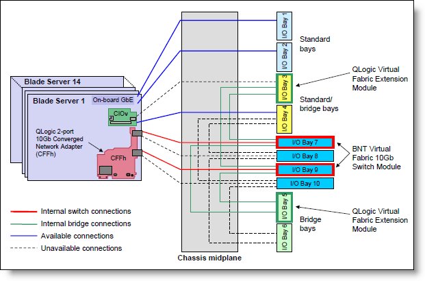
Figure 2. BladeCenter H internal connections with the QLogic Virtual Fabric Extension Module installed
The supported expansion cards that connect to the Virtual Fabric 10 Gb Switch Module are listed in Table 5.
Table 5. Expansion cards supported with the QLogic Virtual Fabric Extension Module
| Expansion card | Part number | Supported |
| QLogic Ethernet and 4 Gb Fibre Channel Card (CFFh) | 39Y9306 | No |
| 2/4 Port Ethernet Expansion Card (CFFh) | 44W4479 | No |
| QLogic Ethernet and 8 Gb Fibre Channel Card (CFFh) | 44X1940 | No |
| Broadcom 10Gb 2-port Ethernet Expansion Card | 44W4466 | No |
| Broadcom 10Gb 4-port Ethernet Expansion Card | 44W4465 | No |
| Broadcom 10 Gb Gen 2 2-port Ethernet Expansion Card | 46M6168 | No |
| Broadcom 10 Gb Gen 2 4-port Ethernet Expansionping Card | 46M6164 | No |
| Broadcom 2-port 10Gb Virtual Fabric Adapter | 81Y3133 | No |
| Emulex 10GbE Virtual Fabric Adapter | 49Y4235 | No |
| Emulex 10GbE Virtual Fabric Adapter Advanced | 49Y4275 | No |
| Emulex 10GbE Virtual Fabric Adapter II | 90Y3550 | No |
| Emulex 10GbE Virtual Fabric Adapter II Advanced | 90Y3566 | Yes |
| Intel 2-port 10Gb Ethernet Expansion Card | 42C1810 | No |
| Mellanox 2-port 10Gb Ethernet Expansion Card | 90Y3570 | No |
| NetXen 10Gb Ethernet Expansion Card | 39Y9271 | No |
| QLogic 2-port 10Gb Converged Network Adapter | 42C1830 | Yes |
Supported configurations
As described in the previous section, the three components in this configuration are:
- A supported expansion card (see Table 5)
- Virtual Fabric 10 Gb Switch Module
- QLogic Virtual Fabric Extension Module
These components are supported together in the BladeCenter chassis in three possible configurations:
Configuration 1: Maximum redundancy and bandwidth
- Two switch modules in bays 7 and 9 of the chassis
- Two extension modules in bays 3 and 5
- One supported expansion card in each server
As shown in Figure 2, the switch in bay 7 is connected to the extension module in bay 3, and the switch in bay 9 is connected to the extension module in bay 5. This configuration results in 40 Gbps links between the switch and connected extension module. Four external ports of each switch module (8 total) are disabled (ports 1-4 in bay 7 and ports 7-10 in bay 9) and those circuits are rerouted to the extension modules. This configuration is best for redundancy and bandwidth. Total available external ports: 12 Ethernet, 12 Fibre Channel.
Note: This configuration precludes the use of the bay 3 and bay 4 for I/O modules for use with a CIOv card. You should not install a CIOv card in any blades installed in this chassis.
We show this configuration in detail in the Popular configurations section below.
Configuration 2: Maximum flexibility
- Two switch modules in bays 7 and 9 of the chassis
- One extension module in bay 5
- One supported expansion card in each server
In this configuration, both the switch in bay 7 and the switch in bay 9 are connected to the extension module in bay 5. See Figure 2 for the connections. This configuration results in 20 Gbps links between each switch and the extension module. Two external ports of each switch module (4 total) are disabled (ports 1 and 2 in bay 7, and ports 9 and 10 in bay 9) and those circuits are rerouted to the extension module. Although the extension module is no longer redundant, it still offers the advantages of two paths from the adapter to the switch and extension module. Unlike configuration 1, this configuration allows the use of the CIOv slot in the blade servers (for example, for SAS connectivity) to connect to I/O modules installed in bays 3 and 4 of the chassis. Total available external ports: 16 Ethernet, 6 Fibre Channel.
We show this configuration in detail in the Popular configurations section below.
Configuration 3: Entry level
- One switch module in bay 7 (or bay 9) of the chassis
- One extension module in bay 5 (or bay 3)
- One supported expansion card in each server
In this configuration, only one port of the Converged Network Adapter is active and one path is established from the adapter to the switch and on to the extension module. This configuration results in a 40 Gbps link between the switch and extension module. Four external ports of the switch module are disabled (ports 1-4 if bay 7 is used or ports 7-10 if bay 9 is used) and those circuits are rerouted to the extension module. This configuration does not offer any redundancy, but does maximize bandwidth to the extension module. If the extension module is installed in bay 5, then configuration allows the use of the CIOv slot in the blade servers to connect to I/O modules installed in bays 3 and 4 of the chassis. Total available external ports: 6 Ethernet, 6 Fibre Channel
Table 6 compares the number of available external ports in these configurations.
Table 6. Comparing the supported configurations
| Configuration | Total Ethernet ports | Total Fibre Channel ports |
| 1 | 12 | 12 |
| 2 | 16 | 6 |
| 3 | 6 | 6 |
Popular configurations
This section shows how you can use the QLogic Virtual Fabric Extension Module in configurations.
Two QLogic Virtual Fabric Extension Modules and two Virtual Fabric Switch Modules
As shown in Figure 3 (see also Figure 2), the switch in bay 7 is connected to the extension module in bay 3, and the switch in bay 9 is connected to the extension module in bay 5. This configuration results in 40 Gbps links between the switch and connected extension module. Four external ports of each switch module are disabled (ports 1-4 in bay 7 and ports 7-10 in bay 9) and those circuits are rerouted to the extension modules.
Figure 3. Converged networking solution with two QLogic Virtual Fabric Extension Modules and two Virtual Fabric 10 Gb Switch Modules
The components used in this configuration are listed in Table 7.
Table 7. Components of converged networking solution with two QLogic Virtual Fabric Extension Modules and two Virtual Fabric 10 Gb Switch Modules
| Diagram reference | Part number | Description | Quantity |
| Varies | BladeCenter HS22 or server that supports the QLogic 2-port 10 Gb Converged Network Adapter (CFFh) | 1 to 14 | |
| 42C1830 | QLogic 2-port 10 Gb Converged Network Adapter (CFFh) | 1 per server | |
| 8852 | BladeCenter H chassis | 1 | |
| 46C7191 | Virtual Fabric 10 Gb Switch Module | 2 | |
| 44W4408 | 10GBase-SR SFP+ Transceiver | Up to 12* | |
| 46M6172 | QLogic Virtual Fabric Extension Module | 2 | |
| 44X1964 | 8 Gb SFP+ SW Optical Transceiver | Up to 12 |
* While Virtual Fabric 10 Gb Switch Module has ten external 10 Gb ports, the configuration described above allows use of only up to six external ports on each switch because four 10 Gb external ports are remapped to four internal connections to each QLogic Virtual Fabric Expansion Module, as shown on Figure 3.
Note: You can use one Virtual Fabric 10 Gb Switch Module and one QLogic Virtual Fabric Expansion Module in the configuration described above. In this case, Virtual Fabric 10 Gb Switch Module is installed into I/O bay 7 and one QLogic Virtual Fabric Expansion Module is installed into I/O bay 3 or Virtual Fabric 10 Gb Switch Module is installed into I/O bay 9 and one QLogic Virtual Fabric Expansion Module is installed into I/O bay 5 of the BladeCenter H chassis. Up to six external 10 Gb Ethernet ports and up to six external FC ports are available in this configuration.
One QLogic Virtual Fabric Extension Module and two Virtual Fabric Switch Modules
In this configuration, two switches are installed in bay 7 and bay 9 and both are connected to the extension module in bay 5. See Figure 2 and Figure 3 for the connections. This configuration results in 20 Gbps links between each switch and the extension module. Two external ports of each switch module are disabled (ports 1 and 2 in bay 7, and ports 9 and 10 in bay 9) and those circuits are rerouted to the extension module. The components used in this configuration are listed in Table 8.
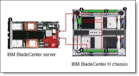
Figure 4. Converged networking solution with one QLogic Virtual Fabric Extension Module and two Virtual Fabric 10 Gb Switch Modules
Table 8. Components of converged networking solution with one QLogic Virtual Fabric Extension Module and two Virtual Fabric 10 Gb Switch Modules
| Diagram reference | Part number | Description | Quantity |
| Varies | BladeCenter HS22 or server that supports the QLogic 2-port 10 Gb Converged Network Adapter (CFFh) | 1 to 14 | |
| 42C1830 | QLogic 2-port 10 Gb Converged Network Adapter (CFFh) | 1 per server | |
| 8852 | BladeCenter H chassis | 1 | |
| 46C7191 | Virtual Fabric 10 Gb Switch Modules in bays 7 and 9 | 2 | |
| 44W4408 | IBM 10GBase-SR SFP+ Transceiver | Up to 16* | |
| 46M6172 | QLogic Virtual Fabric Extension Module in bay 5 | 1 | |
| 44X1964 | IBM 8 Gb SFP+ SW Optical Transceiver | Up to 6 |
* While Virtual Fabric 10 Gb Switch Module has ten external 10 Gb ports, the configuration described above allows use of only up to eight external ports on each switch because two 10 Gb external ports on each switch are remapped to two internal connections to one QLogic Virtual Fabric Extension Module as shown on Figure 4.
Note: QLogic Virtual Fabric Extension Module must be installed in I/O bay 5 of the BladeCenter H chassis.
Connectors and LEDs
Figure 5 shows the front panel of the QLogic Virtual Fabric Extension Module. The six external Fibre Channel ports support the SFP+ optical transceiver modules listed in Table 2.
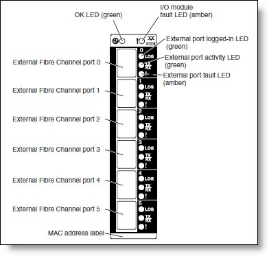
Figure 5. Front panel of the QLogic Virtual Fabric Extension Module
Table 9 lists the LEDs on the front panel and their meanings.
Table 9. LEDs on the front panel
LED name |
LED description |
OK |
This green LED is at the top left of the I/O module on the front panel and indicates that the module is working properly. |
! (I/O module fault) |
This amber LED is at the top right of the I/O module on the front panel. This LED indicates that the I/O module has a fault. If the I/O module fails the POST, this fault LED is lit. |
External port logged-in (LOG) |
There are six green external port logged-in (LOG) LEDs. When one of these LEDs is lit, it indicates that there is a connection (or link) to a device on that port. |
External port activity (TX/RX) |
There are six green external port activity LEDs. When one of these LEDs flashes, it indicates that data is being received or transmitted (that is, activity is occurring) on that port. The flash frequency is proportional to the amount of traffic on that port. |
External port fault (!) |
There are six amber external port fault (!) LEDs. When an external port fault LED is lit, it indicates that the external port has failed the internal, external, or online port diagnostics tests. |
Operating environment
The environment must meet the following temperature and altitude requirements:
- Operating:
- 10 - 52 °C (50 - 125 °F) at an altitude of 0 to 914 m (0 to 3,000 ft)
- 10 - 49 °C (50 - 20 °F) at an altitude of 0 to 3,000 m (0 to 10,000 ft)
- Non-operating:
- 40 - 65 °C (-40 - 149 °F) at an altitude of 0 to 12,000 m (0 to 39,370 ft)
The environment has the following humidity level requirements:
- Operating: 8% to 80%, noncondensing
- Non-operating: 5% to 80%, noncondensing
Related product families
Product families related to this document are the following:
Trademarks
Lenovo and the Lenovo logo are trademarks or registered trademarks of Lenovo in the United States, other countries, or both. A current list of Lenovo trademarks is available on the Web at https://www.lenovo.com/us/en/legal/copytrade/.
The following terms are trademarks of Lenovo in the United States, other countries, or both:
Lenovo®
BladeCenter Interoperability Guide
BladeCenter®
System x®
The following terms are trademarks of other companies:
Intel® is a trademark of Intel Corporation or its subsidiaries.
Other company, product, or service names may be trademarks or service marks of others.


