

Top
Abstract
The BladeCenter 1/10Gb Uplink Ethernet Switch Module is a switch option that enables administrators to offer full Layer 2 and 3 switching and routing capability with combined 1 Gb and 10 Gb uplinks in a BladeCenter chassis. Such consolidation simplifies the data center infrastructure and helps reduce the number of discrete devices, management consoles, and management systems. In addition, the next-generation switch module hardware can support IPv6 Layer 3 frame forwarding protocols by using a future firmware upgrade.
Introduction
The BladeCenter 1/10Gb Uplink Ethernet Switch Module is a switch option that enables administrators to offer full Layer 2 and 3 switching and routing capability with combined 1 Gb and 10 Gb uplinks in a BladeCenter chassis. Such consolidation simplifies the data center infrastructure and helps reduce the number of discrete devices, management consoles, and management systems. In addition, the next-generation switch module hardware can support IPv6 Layer 3 frame forwarding protocols by using a future firmware upgrade.
This Ethernet Switch Module delivers port flexibility, efficient traffic management, increased uplink bandwidth, and strong Ethernet switching price/performance. Figure 1 shows the switch module.

Figure 1. BladeCenter 1/10Gb Uplink Ethernet Switch Module
Did you know?
The switch module's six 1 Gb RJ45 links can be seamlessly deployed in existing Gigabit networks, while its three 10 Gb small form-factor pluggable plus (SFP+) ports provide an easy migration path to 10 Gb networks. The switch also support all nine uplinks being active at the same time, which can also allow for a simply migration without downtime. All nine uplink ports provide line-rate performance with zero packet drop.
VMready allows the switch to dynamically configure itself to coexist with all leading virtual machine providers such as VMware, Microsoft, Citrix XenServer, PowerVM, and Red Hat KVM.
Part number information
The part numbers to order the module and supported optical transceivers are shown in Table 1.
Table 1. Part number and feature code for ordering
| Description | Part number | Feature codes |
| Switch module | ||
| BladeCenter 1/10Gb Uplink Ethernet Switch Module | 44W4404 | 1590 / 6980 / 1590* |
| SFP+ transceivers - 10 GbE | ||
| 10GbE 850 nm Fiber SFP+ Transceiver (SR) | 44W4408 | 4942 |
| IBM SFP+ SR Transceiver | 46C3447 | 5053 |
| IBM SFP+ LR Transceiver | 90Y9412 | A1PM |
| SFP+ direct-attach cables - 10 GbE | ||
| 1m IBM Passive DAC SFP+ Cable | 90Y9427 | A1PH |
| 3m IBM Passive DAC SFP+ Cable | 90Y9430 | A1PJ |
| 5m IBM Passive DAC SFP+ Cable | 90Y9433 | A1PK |
* Feature codes are listed in the form of three codes separated by a forward slash mark (/). The first feature code is for BladeCenter E-, T-, H-, and HT-based configurations that are available through the System x platform. The second feature code is for BladeCenter S-based configurations that are available through the System x sales channel. The third feature code is for BladeCenter S- and BladeCenter H-based configurations that are available through the IBM Power Systems sales channel when applicable.
The part number for the switch, 44W4404, includes the following items:
- One BladeCenter 1/10Gb Uplink Ethernet Switch Module
- 3-meter USB-to-DB9 serial console cable
- Printed documentation
- Documentation CD-ROM
In order to communicate outside of the chassis, you must use a RJ-45 cable such as CAT5 or either one SFP+ transceiver or SFP+ direct-attach copper (DAC) cable connected. Supported options are listed in Table 1.
Benefits
The BladeCenter 1/10Gb Uplink Ethernet Switch Module offers the following benefits:
- All 1 Gb and 10 Gb uplink ports can be active at the same time.
- The switch consumes only 40 Watts, which is ideal for clients with power limitations or for those who simply want to reduce operating cost and be more environmentally friendly.
- It has a large L2 forwarding table (16K), which allows the switch to accommodate a larger flat network with minimum aging activity.
- Advanced L3 functions, such as OSPF and BGP, allow the switch to integrate seamlessly into a large routed network environment.
- L3 functions allow the switch to segregate traffic into segments to improve latency and security within each segment of the network.
Features and specifications
The BladeCenter 1/10Gb Uplink Ethernet Switch Module includes the following standard features and functions:
- Internal ports:
- 14 internal full-duplex Gigabit ports, one connected to each of the blade servers
- Two internal full-duplex 10/100 Mbps ports connected to the management module
- External ports:
- Three slots for 10 Gb Ethernet SFP+ transceivers (support for 10GBASE-SR or 10GBASE-LR) or SFP+ copper direct-attach cables (DAC); SFP+ modules are optional
- Six 10/100/1000 1000BASE-T Gigabit Ethernet ports with RJ-45 connectors
- One RS-232 serial port that provides an additional means to install software and configure the switch module
- Scalability and performance:
- Fixed-speed external 10 Gb Ethernet ports for maximum uplink bandwidth
- Autosensing 10/1000/1000 external Gigabit Ethernet ports for bandwidth optimization
- Non-blocking architecture with wire-speed forwarding of traffic
- Media access control (MAC) address learning: automatic update, support of up to 16 K MAC addresses
- Up to 128 IP interfaces per switch
- Static and LACP (IEEE 802.3ad) link aggregation, up to 36 Gb of total bandwidth per switch, up to 16 trunk groups, up to six ports per group
- Support for jumbo frames (up to 9216 bytes)
- Broadcast/multicast storm control
- IGMP snooping for limit flooding of IP multicast traffic
- IGMP filtering to control multicast traffic for hosts participating in multicast groups
- Configurable traffic distribution schemes over trunk links based on source/destination IP or MAC addresses or both
- Fast port forwarding and fast uplink convergence for rapid STP convergence
- Stacking of up to eight switches
- Availability and redundancy:
- Virtual Router Redundancy Protocol (VRRP) for Layer 3 router redundancy
- IEEE 802.1D STP for providing L2 redundancy
- IEEE 802.1s Multiple STP (MSTP) for topology optimization, up to 128 STP instances are supported by single switch
- IEEE 802.1w Rapid STP (RSTP) provides rapid STP convergence for critical delay-sensitive traffic like voice or video
- Layer 2 Trunk Failover to support active/standby configurations of network adapter teaming on blades
- Interchassis redundancy (L2 and L3)
- VLAN support:
- Up to 1024 VLANs supported per switch, with VLAN numbers ranging from 1 to 4095 (4095 is used for management module’s connection only)
- 802.1Q VLAN tagging support on all ports
- Private VLANs
- Security:
- VLAN-based, MAC-based, and IP-based ACLs
- 802.1X port-based authentication
- Multiple user IDs and passwords
- User access control
- Radius/TACACS+
- Quality of Service (QoS):
- Support for IEEE 802.1p, IP ToS/DSCP, and ACL-based (MAC/IP source and destination addresses, VLANs) traffic classification and processing
- Traffic shaping and re-marking based on defined policies
- Eight Weighted Round Robin (WRR) priority queues per port for processing qualified traffic
- Layer 3 functions:
- IP forwarding
- IP filtering with ACLs, up to 896 ACLs supported
- VRRP for router redundancy
- Support for up to 128 static routes
- Routing protocol support (RIP v1, RIP v2, OSPF v2, BGP-4), up to 2048 entries in a routing table
- Support for DHCP Relay
- IPv6 host management support
- Manageability:
- Simple Network Management Protocol (SNMP V1 and V3)
- HTTP browser GUI
- Telnet interface for CLI
- SSH
- Serial interface for CLI
- Scriptable CLI
- Firmware image update (TFTP and FTP)
- Network Time Protocol (NTP) for switch clock synchronization
- Monitoring:
- Switch LEDs for external port status and switch module status indication
- Port mirroring for analyzing network traffic passing through switch
- Change tracking and remote logging with syslog feature
- POST diagnostics
- Special functions:
- Support for Serial over LAN (SOL)
Standards supported
The switch module supports the following IEEE standards:
- IEEE 802.1D Spanning Tree Protocol (STP)
- IEEE 802.1s Multiple STP (MSTP)
- IEEE 802.1w Rapid STP (RSTP)
- IEEE 802.1p Tagged Packets
- IEEE 802.1Q Tagged VLAN (frame tagging on all ports when VLANs are enabled)
- IEEE 802.1x port-based authentication
- IEEE 802.2 Logical Link Control
- IEEE 802.3 10BASE-T Ethernet
- IEEE 802.3u 100BASE-TX Fast Ethernet
- IEEE 802.3ab 1000BASE-T Gigabit Ethernet
- IEEE 802.3z 1000BASE-X Gigabit Ethernet
- IEEE 802.3ad Link Aggregation Control Protocol
- IEEE 802.3x Full-duplex Flow Control
- IEEE 802.3ae 10GBASE-SR
Supported BladeCenter chassis and expansion cards
The BladeCenter 1/10Gb Uplink Ethernet Switch Module is supported in the BladeCenter chassis listed in Table 2.
Table 2. BladeCenter chassis that support the BladeCenter 1/10Gb Uplink Ethernet Switch Module
| I/O module | Part number | |||||||
| BladeCenter 1/10Gb Uplink Ethernet Switch Module | 44W4404 | Y | Y | Y | Y | Y | Y | Y |
The BladeCenter 1/10Gb Uplink Ethernet Switch Module supports the expansion cards listed in the following table.
Table 3. Supported expansion cards
| Description | Part number | Feature code |
Supported by the 1/10Gb Uplink Ethernet Switch Module |
| Gigabit Ethernet | |||
| Gigabit Ethernet integrated on the server system board | None | None | Supported |
| Ethernet Expansion Card (CFFv) | 39Y9310 | 2969 | Supported |
| Ethernet Expansion Card (CIOv) | 44W4475 | 1039 | Supported |
| 2/4 Port Ethernet Expansion Card (CFFh) | 44W4479 | 5476 | Supported |
| QLogic Ethernet and 8 Gb Fibre Channel Expansion Card | 00Y3270* | A3JC | Supported |
| 10 Gigabit Ethernet (operates at 1 Gb) | |||
| 10Gb Interposer Card for HS23 (uses HS23 Integrated Virtual Fabric LOM) | 94Y8550 | A244 | Supported |
* Replaces 44X1940.
Note: Other 10 GbE Ethernet expansion cards that are not listed in Table 3 are not supported.
The five BladeCenter chassis have the following bays:
- BladeCenter S, E, and T have four standard I/O bays (1, 2, 3, and 4)
- BladeCenter H has six standard I/O bays (1, 2, 3, 4), two bridge bays (5 and 6) and four high-speed bays (7, 8, 9, and 10)
- BladeCenter HT has four standard I/O bays (1, 2, 3, 4) and four high-speed bays (7, 8, 9, and 10).
The BladeCenter 1/10Gb Uplink Ethernet Switch Module fits in a standard I/O bay (bays 1-4). With the addition of the Multi-Switch Interconnect Module (MSIM) in the BladeCenter H and MSIM-HT in the BladeCenter HT, the BladeCenter 1/10Gb Uplink Ethernet Switch Module can also fit in a high-speed I/O bay (bays 7-10). Supported bays are listed in the following table.
Table 4. Supported chassis I/O bays
| Description | Part Number | ||||||||||
|---|---|---|---|---|---|---|---|---|---|---|---|
| Gigabit Ethernet integrated on the server system board | None | Y | Y | N | N | N | N | N | N | N | N |
| Ethernet Expansion Card (CFFv) | 39Y9310 | N | N | Y | Y | N | N | N | N | N | N |
| Ethernet Expansion Card (CIOv) | 44W4475 | N | N | Y | Y | N | N | N | N | N | N |
| 2/4 Port Ethernet Expansion Card (CFFh) | 44W4479 | N | Y* | N | N | N | N | Y | Y | Y | Y |
| QLogic Ethernet and 8 Gb FC Card (CFFh) | 00Y3270 | N | N | N | N | N | N | Y | N | Y | N |
| 10Gb Interposer Card for HS23 | 94Y8550 | N | Y* | N | N | N | N | Y | N | Y | N |
* Supports I/O bay 2 connections only when installed into a blade server that is installed into BladeCenter S chassis.
Popular configurations
This section shows how the BladeCenter 1/10Gb Uplink Ethernet Switch Module can be used in configurations.
Basic two-port configuration
Figure 2 shows basic use of the BladeCenter Ethernet Switch Modules to route the two-port Ethernet controller that is integrated onto the blade server. Two Ethernet Switch Modules are installed in bay 1 and bay 2 of the BladeCenter chassis. The connections between the controller and the switch modules are internal to the chassis. No cabling is needed.
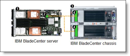
Figure 2. Using BladeCenter Ethernet Switch Modules to route the integrated Ethernet ports
The following table lists the components that are used in the two-port configuration shown in Figure 2.
Table 5. Components used in the two-ports-per-server configuration
| Diagram reference | Part number / machine type | Description | Quantity |
| Varies | BladeCenter HS23 or other supported server | 1 to 14 | |
| None | 1 Gb Ethernet controller on the system board of the server | 1 per server | |
| Varies | Any BladeCenter server (see Table 2) | 1 | |
| 44W4404 | BladeCenter 1/10Gb Uplink Ethernet Switch Module | 2 |
Four-port configuration
Figure 3 shows the use of BladeCenter Ethernet Switch Modules to route four Ethernet ports from each server: the two integrated ports plus two ports supplied by a compatible CFFv or CIOv expansion card. Four Ethernet Switch Modules are installed in bay 1, bay 2, bay 3, and bay 4 of the BladeCenter chassis. All connections between the controller and card and the switch modules are internal to the chassis. No cabling is needed.
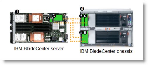
Figure 3. Using BladeCenter 1/10Gb Uplink Ethernet Switch Module to route the four Ethernet ports from the integrated controller and a CFFv or CIOv expansion card
The following table lists the components that are used in the four-port configuration shown in Figure 3.
Table 6. Components used in the four-ports-per-server configuration
| Diagram reference | Part number / machine type | Description | Quantity |
| Varies | BladeCenter HS23 or other supported server | 1 to 14 | |
| None | 1 Gb Ethernet controller on the system board of the server | 1 per server | |
| Varies | Compatible CFFv or CIOv expansion card (see Table 3) | 1 per server | |
| Varies | Any BladeCenter chassis (see Table 2)* | 1 | |
| 44W4404 | BladeCenter 1/10Gb Uplink Ethernet Switch Modules routing signals from the CFFv or CIOv card |
2 | |
| 44W4404 | BladeCenter 1/10Gb Uplink Ethernet Switch Modules routing signals from the integrated controller |
2 |
* The expansion card can be installed in servers in the BladeCenter S (8886). However, by doing so, you lose the ability to connect to the BladeCenter S Disk Storage Modules (DSMs). The Ethernet expansion card go in the place of the SAS expansion card that is needed to connect to the DSMs. This might be appropriate for clients that wants to use external iSCSI storage or need more than four Ethernet ports per blade. If you are simply looking for redundant Ethernet switches or four Ethernet ports per blade consider using the 2/4 Port Ethernet Expansion Card (CFFh), part number 44W4479.
Maximum configuration: Eight Ethernet ports per server
Since BladeCenter servers support a CFFh expansion card plus either a CFFv or CIOv card (depending on the model of the server), you can install up to eight BladeCenter 1/10Gb Uplink Ethernet Switch Modules in a BladeCenter H chassis or BladeCenter HT. Figure 4 shows this eight-port solution. All connections between the cards and the switch modules are internal to the chassis. No cabling is needed.

Figure 4. Using BladeCenter 1/10Gb Uplink Ethernet Switch Module to route eight Ethernet ports per server
The following table lists the components that are used in the eight-Ethernet-ports-per-server configuration shown in Figure 4.
Table 7. Components used in the eight-Ethernet-ports-per-server configuration
| Diagram reference | Part number / machine type | Description | Quantity |
| Varies | BladeCenter HS23 or other supported server | 1 to 14 | |
| None | 1 Gb Ethernet controller on the system board of the server | 1 per server | |
| Varies | Compatible CFFv or CIOv expansion card (see Table 3) | 1 per server | |
| 44W4479 | 2/4 Port Ethernet Expansion Card (CFFh) | 1 per server | |
| 8852 | BladeCenter H chassis | 1 | |
| 44W4404 | BladeCenter 1/10Gb Uplink Ethernet Switch Modules routing signals from the integrated controller |
2 | |
| 44W4404 | BladeCenter 1/10Gb Uplink Ethernet Switch Modules routing signals from the CFFv or CIOv card |
2 | |
| 44W4404 | BladeCenter 1/10Gb Uplink Ethernet Switch Modules routing signals from the CFFh card |
4 | |
| 39Y9314 | Multi-switch Interconnect Module | 2 |
Connectors and LEDs
Figure 5 shows the front panel of the BladeCenter 1/10Gb Uplink Ethernet Switch Module.
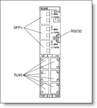
Figure 5. Front panel of the BladeCenter 1/10Gb Uplink Ethernet Switch Module
The front panel contains the following components:
- LEDs that display the status of the switch module and the network. These LEDs are OK, which indicates that the switch module has passed the power-on self-test (POST) with no critical faults and is operational, and switch module error, which indicates that the switch module has failed the POST or detected an operational fault.
- One USB RS-232 console port that provides an additional means to install software and configure the switch module. This USB-style connector enables connection of a special serial cable that is supplied with the switch module.
- Six external 1000BASE-T Ethernet ports for 10/100/1000 Mbps connections to external Ethernet devices.
- Three external SFP+ port connectors to attach SFP+ modules for 1000 Mbps connections to external Ethernet devices.
- An Ethernet link OK LED and an Ethernet Tx/Rx LED for each external port on the switch module.
Network cabling requirements
The network cables that can be used with the switch are shown in the following table.
Table 8. IBM 1/10Gb Uplink switch network cabling requirements
| Transceiver | Standard | Cable | Connector |
| 10 Gb Ethernet | |||
| IBM SFP+ SR Transceiver (46C3447) | 10GBASE-SR | 850 nm multimode fiber cable (50 µ or 62.5 µ) up to 300 m | LC |
| IBM SFP+ LR Transceiver (90Y9412) | 10GBASE-LR | 1310 nm single-mode fiber cable up to 10 km | LC |
| 10GBase-SR SFP+ (MMFiber) transceiver (44W4408) | 10GBASE-SR | 850 nm multimode fiber cable (50 µ or 62.5 µ) up to 300 m | LC |
| Direct attach cable | 10GSFP+Cu | SFP+ DAC cables up to 5 m (see Table 1) | SFP+ |
| 1 Gb Ethernet | |||
| Fixed RJ-45 1 GbE port | 1000BASE-T | UTP Category 5, 5E, and 6 up to 100 meters | RJ-45 |
| Management port | |||
| External RS-232 management port | RS-232 | DB-9-to-USB 3 m console cable (comes with the switch) | USB |
Related product families
Product families related to this document are the following:
Trademarks
Lenovo and the Lenovo logo are trademarks or registered trademarks of Lenovo in the United States, other countries, or both. A current list of Lenovo trademarks is available on the Web at https://www.lenovo.com/us/en/legal/copytrade/.
The following terms are trademarks of Lenovo in the United States, other countries, or both:
Lenovo®
BladeCenter Interoperability Guide
BladeCenter®
System x®
VMready®
The following terms are trademarks of other companies:
Microsoft® is a trademark of Microsoft Corporation in the United States, other countries, or both.
Other company, product, or service names may be trademarks or service marks of others.


