

Top
Abstract
The IBM BladeCenter Layer 2/3 Copper and Fiber Gigabit Ethernet Switch Modules are switch options that enable administrators to consolidate full Layer 2-3 LAN switching and routing capabilities into a BladeCenter chassis. Consolidation flattens the topology of the data center infrastructure and reduces the number of discrete devices, management consoles, and different management systems.
Introduction
As business applications become more and more demanding, data centers have become more complex, cumbersome, and expensive to manage. IBM BladeCenter offers solutions to help lower costs while enhancing performance by accommodating many integration technologies.
The IBM BladeCenter Layer 2/3 Switch offers all the switching features in a BladeCenter chassis at a competitive price. This switch is offered in two versions: Copper and Fiber. These versions provide reliability and flexibility and meet all the stringent requirements of both enterprise and telecom environments. Figure 1 shows the two switch modules.
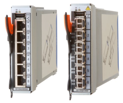
Figure 1. IBM BladeCenter Layer 2/3 Copper (left) and Fiber (right) Gigabit Ethernet Switch Modules
Did you know?
Clients do not need the most expensive switches to manage their virtualization requirements. These low cost switches offer the maximum uplink bandwidth and a low blocking ratio for maximum performance, while consuming extremely lower power at only 27W. The fiber model is ideal for those who need to carry data greater distances, want better security since it is difficult to tap and does not radiate data, or look for better reliability because it is immune to electromagnetic interference.
Part number information
Table 1 shows the part numbers to order these modules.
Table 1. Part number and feature code for ordering
| Description | Part number | Feature codes* |
| IBM BladeCenter Layer 2/3 Copper Gigabit Ethernet Switch Module | 32R1860 | 1495 / 3212 / 3212 |
| IBM BladeCenter Layer 2/3 Fiber Gigabit Ethernet Switch Module | 32R1861 | 1496 / 3213 / 3213 |
* The first feature code is for BladeCenter E-, T-, H-, and HT-based configurations that are available through x-config. The second feature code is for BladeCenter S-based configurations that are available through x-config. The third feature code is for BladeCenter S- and BladeCenter H-based configurations that are available through e-config when applicable.
The part numbers include the following items:
- One IBM BladeCenter Layer 2/3 Copper Gigabit Ethernet Switch Module or IBM BladeCenter Layer 2/3 Fiber Gigabit Ethernet Switch Module with six small form-factor pluggable (SFP) SX transceivers
- 3-meter Universal Serial Bus (USB)-to-DB9 serial console cable
- Printed documentation
- Documentation CD-ROM
Benefits
The IBM BladeCenter Layer 2/3 Copper and Fiber Gigabit Ethernet Switch Modules offer the following benefits:
- Integration and consolidation: These switches offer integration within the BladeCenter chassis, enabling clients to consolidate full Layer 2-3 LAN switching and routing capabilities into a single chassis. This consolidation helps flatten the data center infrastructure and reduces the number of discrete devices, management consoles, and equipment that administrators must deal with, helping to lower costs and simplify deployment.
- Layer 3 functionality: The switches are two of only a few switch modules in the blade market that include Layer 3 functionality standard, which provides security and performance benefits as inter-VLAN traffic stays within the chassis. These switches also provide the full range of industry-standard Layer 3 protocols from static routes for small and medium business (SMB) customers to technologies, such as Open Shortest Path First (OSPF) and Border Gateway Protocol (BGP).
- Fiber offering: The fiber switch module is ideal for those clients who require fiber for high data rate systems that demand high bandwidth over long distances and require complete immunity to electrical interference.
- Interoperability: These switches interoperate seamlessly with the upstream switches of other vendors.
- Management: These switches are designed to support industry based CLI (Cisco-like) for those who are familiar with IOS, and a full-function Web-based GUI for the latest in simplicity.
- Fault tolerance: These switches automatically learn alternate routes and perform faster convergence in the unlikely case of a link, switch, or power failure. The switch uses proven technologies such as L2 trunk failover, advanced VLAN-based failover, Virtual Router Redundancy Protocol (VRRP), IGMP V3 snooping, and OSPF.
Features and specifications
The IBM BladeCenter Layer 2/3 Copper and Fiber Gigabit Ethernet Switch Modules for standard mode of operation includes the following features and functions:
- Internal ports
- 14 internal full-duplex Gigabit ports, one connected to each of the blade servers in the BladeCenter unit
- Two internal full-duplex 10/100 Mbps ports connected to the management module
- External ports
- Copper switch: Six 1000BASE-T copper RJ-45 connections for making 10/100/1000 Mbps connections
- Fiber switch: Six 1000BASE-SX SFP transceiver-based LC fiber connections for making 1000 Mbps connections
- An RS-232 serial port that provides an additional means to install software and configure the switch module
- Scalability and performance
- Autosensing 10/1000/1000 Mbps external Ethernet ports for bandwidth optimization
- Non-blocking architecture with wire-speed forwarding of traffic
- Media access control (MAC) address learning: automatic update, supports up to 16 K MAC addresses
- Up to 128 IP interfaces per switch
- Static, EtherChannel, and LACP (IEEE 802.3ad) link aggregation, up to 6 Gb of total bandwidth per switch, up to three trunk groups, and up to six ports per group
- Support for jumbo frames (up to 9216 bytes)
- Broadcast/multicast storm control
- IGMP snooping for limit flooding of IP multicast traffic (IGMP V1, V2, and V3)
- IGMP filtering to control multicast traffic for hosts participating in multicast groups (IGMP V1, V2, and V3)
- Configurable traffic distribution schemes over trunk links based on source/destination IP addresses, MAC addresses, or both
- Fast port forwarding and fast uplink convergence for rapid STP convergence
- Availability and redundancy
- VRRP for Layer 3 router redundancy
- IEEE 802.1D STP for providing Layer 2 redundancy with PVRST+
- IEEE 802.1s Multiple STP (MSTP) for topology optimization, up to 128 STP instances are supported by single switch
- IEEE 802.1w Rapid STP (RSTP) provides rapid STP convergence for critical delay-sensitive, traffic-like voice or video
- Layer 2 Trunk Failover to support active/standby configurations of network adapter teaming on blades
- Interchassis redundancy (Layer 2 and Layer 3)
- VLAN support
- Up to 1024 VLANs supported per switch; VLAN numbers ranging from 1 to 4095 (4095 is used for the management module’s connection only)
- 802.1Q VLAN tagging support on all ports
- Private VLANs
- Security
- VLAN-based, MAC-based, and IP-based access control lists (ACLs)
- 802.1X port-based authentication
- Multiple user IDs and passwords
- User access control
- Radius/TACACS+
- Quality of Service (QoS)
- Up to eight queues per port
- Support for IEEE 802.1p, IP ToS/DSCP, and ACL-based (MAC/IP source and destination addresses, VLANs) traffic classification and processing
- Traffic shaping and re-marking based on defined policies
- Eight Weighted Round Robin (WRR) priority queues per port for processing qualified traffic
- Layer 3 functions
- IP forwarding
- IP filtering with ACLs (up to 4096 ACLs supported)
- VRRP for router redundancy
- Support for up to 128 static routes
- Routing protocol support (Router Information Protocol (RIP) v1, RIP v2, OSPF v1, v2, and v3, BGP-4), up to 1024 entries in routing table
- Support for DHCP Relay
- Manageability
- Simple Network Management Protocol (SNMP; V1, V2, and V3)
- HTTP/HTTPS browser GUI
- Industry standard CLI and BLADEOS CLI
- Telnet interface for CLI
- SSH
- Serial interface for CLI
- Scriptable CLI
- Firmware image update (TFTP and FTP)
- Network Time Protocol (NTP) for switch clock synchronization
- IBM System Networking Switch Center (SNSC) support
- Monitoring
- Switch LEDs for external port status and switch module status indication
- Port mirroring for analyzing network traffic passing through switch
- Change tracking and remote logging with syslog feature
- POST diagnostics
- Serial over LAN (SOL)
The switch module supports the following IEEE standards:
- IEEE 802.1D STP with PVRST+
- IEEE 802.1s MSTP
- IEEE 802.1w RSTP
- IEEE 802.1p Tagged Packets
- IEEE 802.1Q Tagged VLAN (frame tagging on all ports when VLANs are enabled)
- IEEE 802.1x port-based authentication
- IEEE 802.2 Logical Link Control
- IEEE 802.3ad Link Aggregation Control Protocol
- IEEE 802.3x Full-duplex Flow Control
- For the copper switch module:
- IEEE 802.3 10BASE-T Ethernet
- IEEE 802.3u 100BASE-TX Fast Ethernet
- IEEE 802.3ab 1000BASE-T Gigabit Ethernet
- IEEE 802.3z 1000BASE-X Gigabit Ethernet
- For the fiber switch module:
- IEEE 802.3z 1000BASE-X Gigabit Ethernet
- 1000BASE-SX Gigabit Ethernet
Supported BladeCenter chassis and expansion cards
The IBM Layer 2/3 GbE Switch Modules are supported in the BladeCenter chassis listed in the following table.
Table 2. BladeCenter chassis that support the Layer 2/3 Gigabit Ethernet Switch Modules
| I/O module | Part number |
|
|
|
|
|
|
|
| IBM Layer 2/3 Copper Gigabit Ethernet Switch Module | 32R1860 | Y | Y | Y | Y | Y | Y | Y |
| IBM Layer 2/3 Fiber Gigabit Ethernet Switch Module | 32R1861 | Y | Y | Y | Y | Y | Y | N |
The IBM Layer 2/3 GbE Switch Modules support the expansion cards listed in the following table.
Table 3. Supported expansion cards
| Description | Part number | Feature code | Supported by the Layer 2/3 GbE Switch |
| Gigabit Ethernet | |||
| Gigabit Ethernet integrated on the server system board | None | None | Supported |
| Ethernet Expansion Card (CFFv) | 39Y9310 | 2969 | Supported |
| Ethernet Expansion Card (CIOv) | 44W4475 | 1039 | Supported |
| 2/4 Port Ethernet Expansion Card (CFFh) | 44W4479 | 5476 | Supported |
| QLogic Ethernet and 8 Gb Fibre Channel Expansion Card | 00Y3270* | A3JC | Supported |
* Replaces 44X1940.
Note: 10 Gb Ethernet expansion cards are not supported by the Layer 2/3 GbE Switch Module.
The five BladeCenter chassis have the following bays:
- BladeCenter S, E, and T have four standard I/O bays (1, 2, 3, and 4)
- BladeCenter H has six standard I/O bays (1, 2, 3, 4), two bridge bays (5 and 6) and four high-speed bays (7, 8, 9, and 10)
- BladeCenter HT has four standard I/O bays (1, 2, 3, 4) and four high-speed bays (7, 8, 9, and 10).
The IBM BladeCenter Layer 2/3 Copper and Fiber Gigabit Ethernet Switch Modules fit in a standard I/O bay (bays 1-4). The IBM BladeCenter Layer 2/3 Copper Ethernet Switch Module, with the addition of the Multi-Switch Interconnect Module (MSIM) in the BladeCenter H and HT chassis, can also fit in a high-speed I/O bay (bays 7-10). The IBM BladeCenter Layer 2/3 Fiber Gigabit Ethernet Switch Module is supported in the BladeCenter H chassis with MSIM (bays 7-10) but is not supported with MSIM-HT in the high-speed bays of the BladeCenter HT chassis. Supported bays are listed in the following table.
Table 4. IBM BladeCenter Layer 2/3 Copper and Fiber Gigabit Ethernet Switch Modules and BladeCenter chassis I/O bays support
| Gigabit Ethernet integrated on the server system board | None | Y | Y | N | N | N | N | N | N | N | N |
| Ethernet Expansion Card (CFFv) | 39Y9310 | N | N | Y | Y | N | N | N | N | N | N |
| Ethernet Expansion Card (CIOv) | 44W4475 | N | N | Y | Y | N | N | N | N | N | N |
| QLogic Ethernet and 4 Gb FC Card (CFFh) | 39Y9306 | N | N | N | N | N | N | Y | N | Y | N |
| 2/4 Port Ethernet Expansion Card (CFFh) | 44W4479 | N | Y* | N | N | N | N | Y | Y | Y | Y |
| QLogic Ethernet and 8 Gb FC Card (CFFh) | 00Y3270 | N | N | N | N | N | N | Y | N | Y | N |
* The 2/4 Port Ethernet Expansion Card supports I/O bay 2 connections only when installed into a blade server that is installed in the BladeCenter S chassis.
Popular configurations
The IBM BladeCenter Layer 2/3 Copper and Fiber Gigabit Ethernet Switch Modules can be used in various configurations.
Basic two-port configuration
Figure 2 shows a basic use of the switch to route the two-port Ethernet controller that is integrated onto the blade server. Two switches are installed in bay 1 and bay 2 of the BladeCenter chassis. The connections between the controller and the switch modules are internal to the chassis. No wiring is needed.
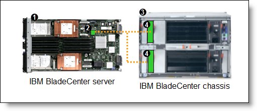
Figure 2. Using IBM BladeCenter Ethernet Switch Modules to route the integrated Ethernet ports
The following table lists the components that are used in this configuration.
Table 5. Components used in two-ports-per-server configuration
| Diagram reference | Part number / machine type | Description | Quantity |
| Varies | IBM BladeCenter HS23 or other supported server | 1 to 14 | |
| None | Ethernet controller on the system board of the server | 1 per server | |
| Varies | Any BladeCenter server (see Table 2) | 1 | |
| 32R1860 or 32R1861 | IBM BladeCenter Layer 2/3 Copper or Fiber Gigabit Ethernet Switch Module | 2 |
Four-port configuration
Figure 3 shows the use of switch to route four Ethernet ports from each server: the two integrated ports plus two ports supplied by a compatible CFFv or CIOv expansion card. Four Ethernet Switch Modules are installed in bay 1, bay 2, bay 3, and bay 4 of the BladeCenter chassis. All connections between the controller, card, and the switch modules are internal to the chassis. No wiring is needed.
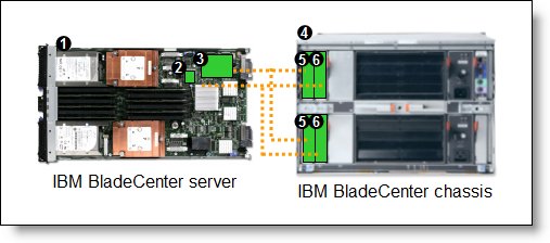
Figure 3. Using IBM BladeCenter Ethernet Switch Modules to route the four Ethernet ports from the integrated controller and a CFFv or CIOv expansion card
The following table lists the components that are used in this configuration.
Table 6. Components used in the four ports-per-server configuration
| Diagram reference | Part number / machine type | Description | Quantity |
| Varies | IBM BladeCenter HS23 or other supported server | 1 to 14 | |
| None | Ethernet controller on the system board of the server | 1 per server | |
| Varies | Compatible CFFv or CIOv expansion card (see Table 3) | 1 per server | |
| Varies | Any BladeCenter chassis (See Table 2)* | 1 | |
| 32R1860 or 32R1861 | IBM BladeCenter Ethernet Switch Modules routing signals from the CFFv or CIOv card |
2 | |
| 32R1860 or 32R1861 | IBM BladeCenter Ethernet Switch Modules routing signals from the integrated controller |
2 |
* The expansion card can be installed in servers in the BladeCenter S (8886). However, by doing so, you lose the ability to connect to the BladeCenter S Disk Storage Modules (DSMs). The Ethernet expansion card goes in the place of the SAS expansion card that is needed to connect to the DSMs. Instead, use the 2/4 Port Ethernet Expansion Card (CFFh), part number 44W4479.
Maximum configuration: Eight Ethernet ports per server
Since BladeCenter servers support both a CFFh expansion card, plus either a CFFv or CIOv card (depending on the model of the server), you can install up to eight IBM BladeCenter Layer 2/3 Copper or Fiber Gigabit Ethernet Switch Modules in a BladeCenter H chassis and up to eight IBM BladeCenter Layer 2/3 Copper ESM in a BladeCenter HT. Figure 4 shows this 8-port solution. All connections between the cards and the switch modules are internal to the chassis. No wiring is needed.

Figure 4. Using IBM BladeCenter Ethernet Switch Modules to route eight Ethernet ports per server
The following table lists the components that are used in this configuration.
Table 7. Components used in the eight-ports-per-server configuration
| Diagram reference | Part number / machine type | Description | Quantity |
| Varies | IBM BladeCenter HS23 or other supported server | 1 to 14 | |
| None | Ethernet controller on the system board of the server | 1 per server | |
| Varies | Compatible CFFv or CIOv expansion card (see Table 3) | 1 per server | |
| 44W4479 | 2/4 Port Ethernet Expansion Card (CFFh) | 1 per server | |
| 8852 | BladeCenter H chassis | 1 | |
| 32R1860 or 32R1861 | IBM BladeCenter Ethernet Switch Modules routing signals from the integrated controller |
2 | |
| 32R1860 or 32R1861 | IBM BladeCenter Ethernet Switch Modules routing signals from the CFFv or CIOv card |
2 | |
| 32R1860 or 32R1861 | IBM BladeCenter Ethernet Switch Modules routing signals from the CFFh card |
4 | |
| 39Y9314 | Multi-switch Interconnect Module | 2 |
Connectors and LEDs
Figure 5 shows the front panel of the IBM BladeCenter Layer 2/3 Copper and Fiber Gigabit Ethernet Switch Modules.
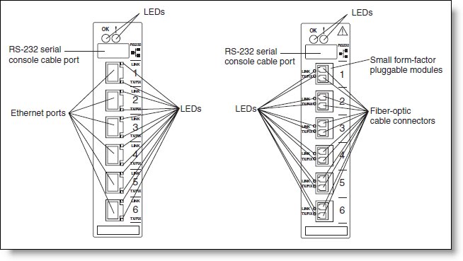
Figure 5. Front panel of the IBM BladeCenter Layer 2/3 Copper (left) and Fiber (right) Gigabit Ethernet Switch Modules
The front panel contain the following components:
- LEDs display the status of the switch module and the network: OK (indicating that the switch module has passed the power-on self-test (POST) with no critical faults and is operational) and switch module error (indicating that the switch module has failed the POST or detected an operational fault).
- One USB RS-232 console port provides an additional means to install software and configure the switch module. This USB-style connector enables connection of a special serial cable that is supplied with the switch module.
- The copper model of the switch module has six external 1000BASE-T Ethernet ports for 10/100/1000 Mbps connections to external Ethernet devices.
- The fiber model of the switch module has six external 1000BASE SX SFP transceiver ports for 1000 Mbps connections to external Ethernet devices.
- Each external port on the switch module contains an Ethernet link OK LED and an Ethernet Tx/Rx LED.
Network cabling requirements
The following network cables are required for the fiber switch module:
- 1000BASE-SX: 850 Nm wavelength, multimode fiber, 50 µ or 62.5 µ (550 meters maximum), with LC duplex connector
Note: Fiber connections use SFP transceivers that provide 1000BASE-SX (850 nm wavelength) communications over multimode fiber cables (50 µ or 62.5 µ) for distances of up to 550 meters.
The following network cables are required for the copper switch module:
- 10BASE-T:
- UTP Category 3, 4, 5 (100 meters (328 feet) maximum)
- 100-ohm STP (100 meters maximum)
- 100BASE-TX:
- UTP Category 5 (100 meters maximum)
- EIA/TIA-568 100-ohm STP (100 meters maximum)
- 1000BASE-T:
- UTP Category 6
- UTP Category 5e (100 meters maximum)
- UTP Category 5 (100 meters maximum)
- EIA/TIA-568B 100-ohm STP (100 meters maximum)
Related product families
Product families related to this document are the following:
Trademarks
Lenovo and the Lenovo logo are trademarks or registered trademarks of Lenovo in the United States, other countries, or both. A current list of Lenovo trademarks is available on the Web at https://www.lenovo.com/us/en/legal/copytrade/.
The following terms are trademarks of Lenovo in the United States, other countries, or both:
Lenovo®
BLADEOS
BladeCenter®
Other company, product, or service names may be trademarks or service marks of others.


