

Top
Abstract
Lenovo NeXtScale System is an open, flexible, and simple data center solution for users of technical computing, grid deployments, analytics workloads, and large-scale cloud and virtualization infrastructures. The NeXtScale nx360 M5 compute node is a ½U two-socket server and is now based on Intel Xeon E5-2600 v4 processors.
This product guide provides essential pre-sales information to understand the NeXtScale System M5 offerings, their key features and specifications, components and options, and configuration guidelines.
This guide is intended for technical specialists, sales specialists, sales engineers, IT architects, and other IT professionals who want to learn more about NeXtScale System and consider its use in IT solutions.
Withdrawn from marketing: The models covered in this product guide are now withdrawn from marketing. The replacement system is the ThinkSystem SD530 which is described in https://lenovopress.com/lp0635.
Note: There are two Product Guides for the NeXtScale nx360 M5, as follows:
- nx360 M5 (E5-2600 v4) – this product guide
- nx360 M5 (E5-2600 v3) – see http://lenovopress.com/tips1195
Introduction
NeXtScale System is an open, flexible, and simple data center solution for users of technical computing, grid deployments, analytics workloads, and large-scale cloud and virtualization infrastructures. The NeXtScale n1200 enclosure and NeXtScale nx360 M5 server are designed to optimize density and performance within typical data center infrastructure limits. The 6U NeXtScale n1200 enclosure fits in a standard 19-inch rack and up to 12 nx360 M5 servers can be installed into the enclosure. With more computing power per watt and the new Intel Xeon v4 processors, you can reduce costs while maintaining speed and availability.
Suggested use: HPC, technical computing, grid deployments, analytics workloads, and large-scale cloud, managed service providers, and virtualization infrastructures
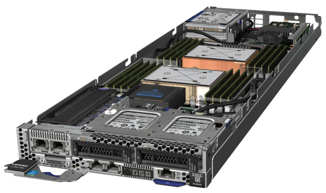
Figure 1. The NeXtScale nx360 M5 server
Did you know?
The NeXtScale nx360 M5 with Intel Xeon v4 processors now supports faster DDR4 memory at up to 2400 MHz. Processor core counts have also increased and the server now supports up to 22 cores per processor, up from 18 cores in the v3 processors.
The NeXtScale System is built with industry-standard components to create flexible configurations of servers, chassis, and networking switches that integrate easily in a standard 19-inch rack. It is a general-purpose platform that provides flexibility to clients for creating unique and differentiated solutions using off-the-shelf components. Front-access cabling enables you to quickly and easily make changes in networking, power connections, and storage. The nx360 M5 and n1200 enclosure are also available in direct-water cooled configurations for the ultimate in data center cooling efficiencies.
Key features
The NeXtScale offering includes a dense chassis, half wide compute nodes, plus storage and GPU nodes, all fitting within a standard rack footprint. NeXtScale is well suited for High Performance Computing and in particular workloads requiring dense performance, such as Cloud, Grid, and Analytics.
Designed with industry-standard, off-the-shelf components, NeXtScale System is a general-purpose platform that is designed to give customers a flexible IT infrastructure. The offering includes compute-intensive systems, and GPU offerings and storage offerings. Customized solutions can be configured to provide an application-appropriate platform with a choice of servers, networking switches, adapters, and racks.
This modular system is designed to scale and grow with data center needs to protect and maximize IT investments. Because it is optimized for standard racks, users can easily mix high-density NeXtScale server offerings and non-NeXtScale components within the same rack. NeXtScale System also provides tremendous time to value by enabling users to set up and start it in a shorter period.
The NeXtScale nx360 M5 server provides a dense, flexible solution with a low total cost of ownership (TCO). The half-wide, dual-socket NeXtScale nx360 M5 server is designed for data centers that require high performance but are constrained by floor space. By taking up less physical space in the data center, the NeXtScale server enhances density, and it supports the Intel Xeon processor E5-2600 v4 series up to 145 W and 22-core processors, thus providing more performance per server. The nx360 M5 compute node contains only essential components in the base architecture to provide a cost-optimized platform.
The nx360 M5 also supports additional expansion options in the form of trays that attach to the top of the server. The PCIe Native Expansion Tray can be added to the nx360 M5 to form a powerful compute engine, supporting two GPU or coprocessor adapters. Also offered is the Storage Native Expansion Tray, which can be added to the nx360 M5 to form a storage-dense server supporting up to 48 TB of local SAS-attached storage.
The NeXtScale n1200 Enclosure is an efficient, 6U, 12-node chassis with no built-in networking or switching capabilities, and therefore requires no chassis-level management. Sensibly designed to provide shared, high-efficiency power and cooling for housed servers, the n1200 enclosure is designed to scale with your business needs.
The NeXtScale nx360 M5 is also available as a warm-water-cooled server for the ultimate in energy efficiency, cooling, noise, and TCO.
Scalability and performance
The NeXtScale System and the NeXtScale nx360 M5 server offer numerous features to boost performance, improve scalability, and reduce costs:
- Up to 12 compute nodes, each with two of the latest Xeon v4 processors, 16 DIMMs, and three PCIe slots, in 6U of rack space. It is a highly dense, scalable, and price-optimized offering.
- The Intel Xeon processor E5-2600 v4 product family improves productivity by offering superior system performance with 22-core processors, core speeds up to 3.5 GHz, L3 cache sizes up to 55 MB, DDR4 memory speeds up to 2400 MHz, and QPI interconnect links of up to 9.6 GTps.
- Two processors, up to 44 cores, and 88 threads maximize the concurrent execution of multi-threaded applications.
- Intelligent and adaptive system performance with Intel Turbo Boost Technology 2.0 allows CPU cores to run at maximum speeds during peak workloads by temporarily going beyond processor thermal design power (TDP).
- Intel Hyper-Threading Technology boosts performance for multi-threaded applications by enabling simultaneous multi-threading within each processor core, up to two threads per core.
- Intel Virtualization Technology integrates hardware-level virtualization hooks that allow operating system vendors to better use the hardware for virtualization workloads.
- Intel Advanced Vector Extensions 2 (AVX2) improve floating-point performance for compute-intensive technical and scientific applications.
- Sixteen DIMMs of registered 2400 MHz DDR4 ECC memory provide speed, high availability, and a memory capacity of up to 512 GB.
- Supports drives up to 8 TB capacity in the 3.5-inch form factor.
- Support for internal simple-swap drives, either one 3.5-inch drive or two 2.5-inch drives. Plus, in place of a PCIe slot, add two 2.5-inch hot-swap drives.
- Support for additional local storage with the use of the 12G Storage Native Expansion Tray. When using 8 TB HDDs, you can create an ultra-dense storage server with up to 64 TB of total disk capacity within 1U of comparable rack density. The nx360 M5 with the Storage Native Expansion Tray offers a perfect solution for today’s data-intensive workloads.
- Boosts performance with PCIe Native Expansion Tray by offering support for two high-powered GPUs or Intel Xeon Phi coprocessors within a single node.
- The use of solid-state drives (SSDs) instead of or with traditional hard disk drives (HDDs) can improve I/O performance. An SSD can support up to 100 times more I/O operations per second (IOPS) than a typical HDD.
- Three PCIe slots internal to the nx360 M5: Full-height PCIe slot, mezzanine LOM Generation 2 (ML2) slot, and dedicated internal RAID adapter slot.
- Supports new mezzanine LOM Generation 2 (ML2) cards for 40 Gb Ethernet and FDR InfiniBand that offer network performance in the smallest footprint.
- PCI Express 3.0 I/O expansion capabilities improve the theoretical maximum bandwidth by 60% compared with the previous generation of PCI Express 2.0.
- With Intel Integrated I/O Technology, the PCI Express 3.0 controller is integrated into the Intel Xeon processor E5 family, which reduces I/O latency and increases overall system performance.
Manageability and security
Powerful systems management features simplify local and remote management of the nx360 M5:
- Support for Lenovo XClarity Administrator, providing auto-discovery, inventory tracking, monitoring, policy-based firmware updates, address pool management, configuration patterns and operating system installation.
- The server includes an Integrated Management Module II (IMM 2.1) to monitor server availability and perform remote management.
- There is a standard Ethernet port that can be shared between the operating system and IMM for remote management with optional Features on Demand upgrade. There is an optional additional Ethernet port for dedicated IMM connectivity.
- An integrated industry-standard Unified Extensible Firmware Interface (UEFI) enables improved setup, configuration, and updates, and simplifies error handling.
- Integrated Trusted Platform Module (TPM) 1.2 and 2.0 support (TPM 2.0 requires UEFI 2.21 or later) enables advanced cryptographic functionality, such as digital signatures and remote attestation.
- Intel Trusted Execution Technology provides enhanced security through hardware-based resistance to malicious software attacks, allowing the application to run in its own isolated space that is protected from all other software running on a system.
- The Intel Execute Disable Bit function can prevent certain classes of malicious buffer overflow attacks when combined with a supporting operating system.
Energy efficiency
The NeXtScale System offers the following energy efficiency features to save energy, reduce operational costs, increase energy availability, and contribute to a green environment:
- The server is Energy Star 2.1 compliant
- Support for S3 standby power states in the processor (requires specific hardware components, software and operating system; contact Lenovo product management for details).
- Shared 80 PLUS Platinum-certified power supplies ensure energy efficiency.
- Large 80 mm fans maximize air flow efficiencies.
- The Intel Xeon processor E5-2600 v4 product family offers better performance per watt over the previous generation.
- Intel Intelligent Power Capability powers on and off individual processor elements as needed to reduce power draw.
- Low-voltage Intel Xeon processors draw less energy to satisfy the demands of power and thermally constrained data centers and telecommunication environments.
- Low-voltage 1.2 V DDR4 memory DIMMs consume up to 20% less energy compared to 1.35 V DDR3 DIMMs.
- SSDs consume as much as 80% less power than traditional 2.5-inch HDDs.
- The server uses hexagonal ventilation holes in the front and rear of the casing, which can be grouped more densely than round holes, providing more efficient airflow through the system.
- There are power monitoring and power capping capabilities through the Power and Fan Management Module in the chassis
Availability and serviceability
The NeXtScale System and the nx360 M5 server provide many features to simplify serviceability and increase system uptime:
- The NeXtScale n1200 chassis supports N+N and N+1 power policies for its six power supplies, which means greater system uptime.
- All components can be removed from the front of the rack by sliding out the trays or the chassis for easy, quick servicing.
- Toolless cover removal provides easy access to upgrades and serviceable parts, such as HDDs and memory.
- Optional RAID arrays enable the server to keep operating if there is a failure of any one drive.
- SSDs offer better reliability than traditional mechanical HDDs for greater uptime.
- Predictive Failure Analysis (PFA) detects when system components (processors, memory, and hard disk drives) operate outside of standard thresholds and generates proactive alerts in advance of possible failure, therefore increasing uptime.
- The built-in Integrated Management Module II continuously monitors system parameters, triggers alerts, and performs recovering actions in case of failures to minimize downtime.
- The IMM offers optional remote management capability to enable remote keyboard, video, and mouse (KVM) control of the server.
- There is a three-year customer replaceable unit and onsite limited warranty, with next business day 9x5. Optional service upgrades are available.
Locations of key components and connectors
The following figure shows the front of the nx360 M5 server.
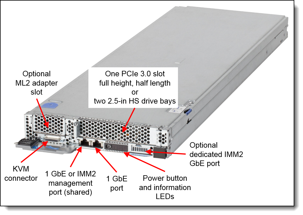
Figure 2. Front view of the NeXtScale nx360 M5
The following figure shows the locations of key components inside the server.
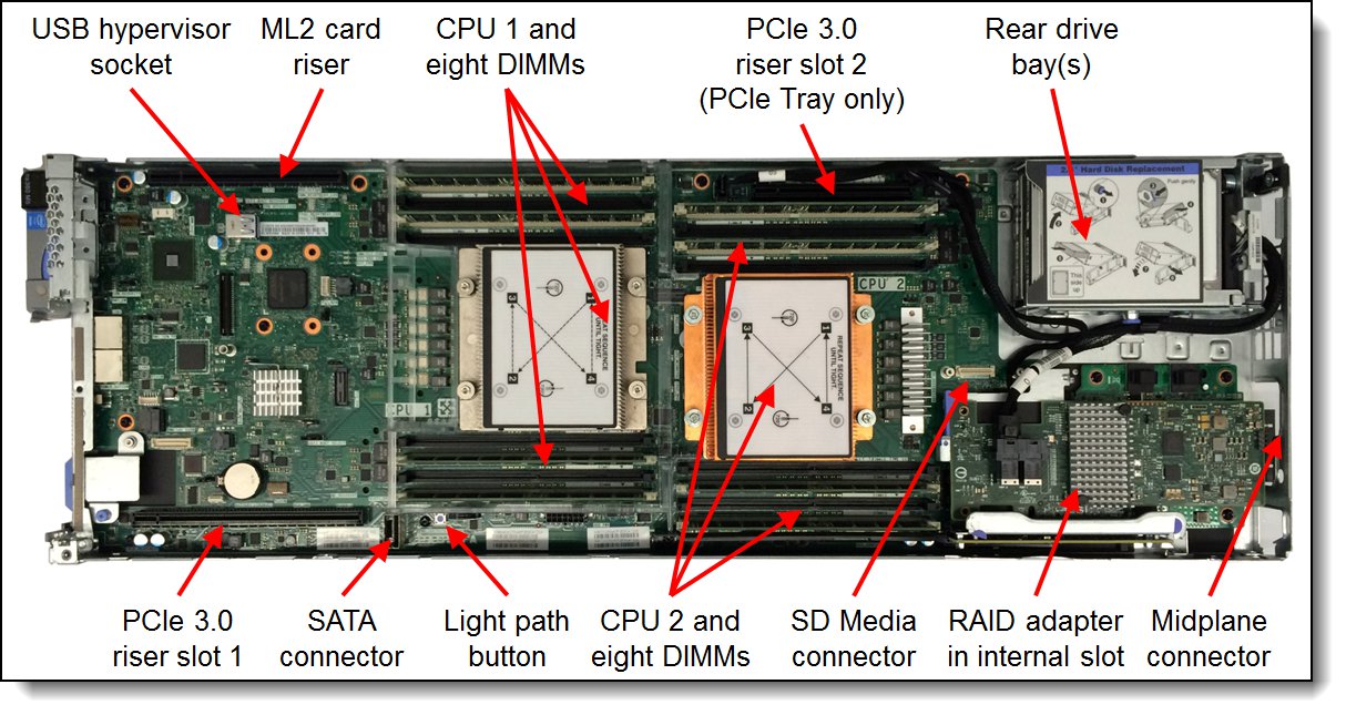
Figure 3. Inside view of the NeXtScale nx360 M5
The compute nodes are installed in the NeXtScale n1200 enclosure, as shown in the following figure.
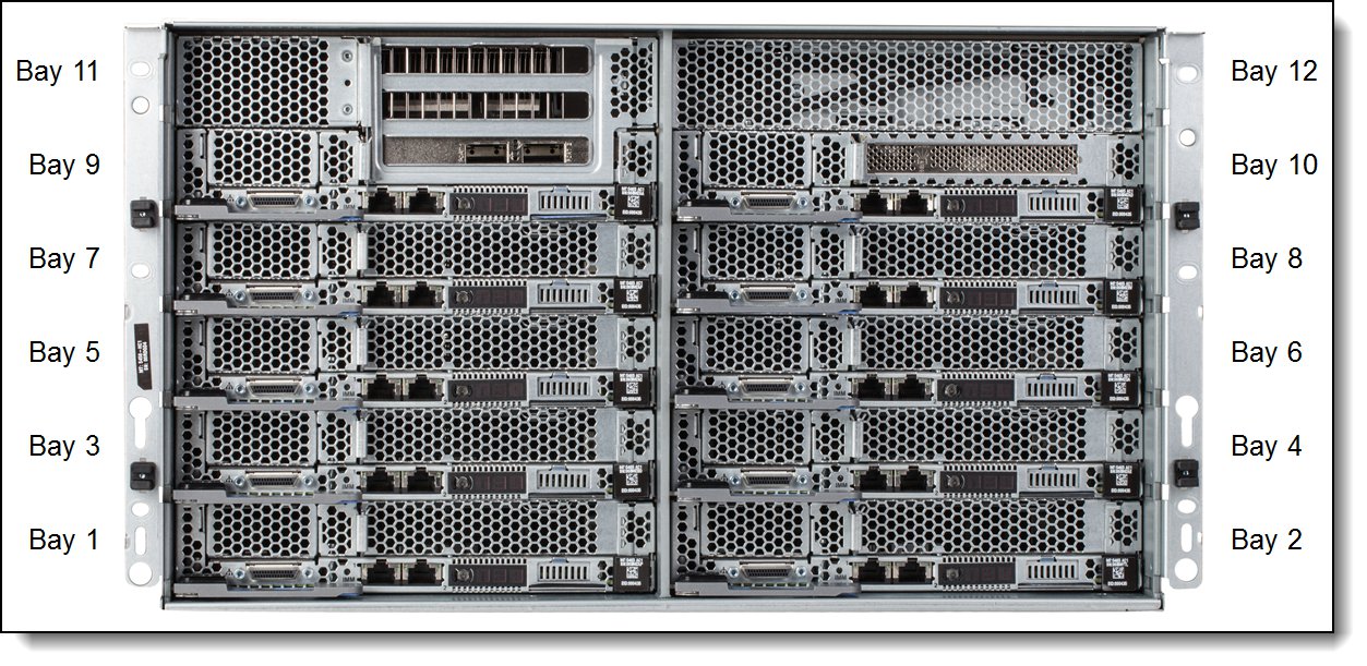
Figure 4. Front view of the NeXtScale n1200 enclosure
The rear of the enclosure contains the power supplies, fans, and the Fan and Power Controller, as shown in the following figure.
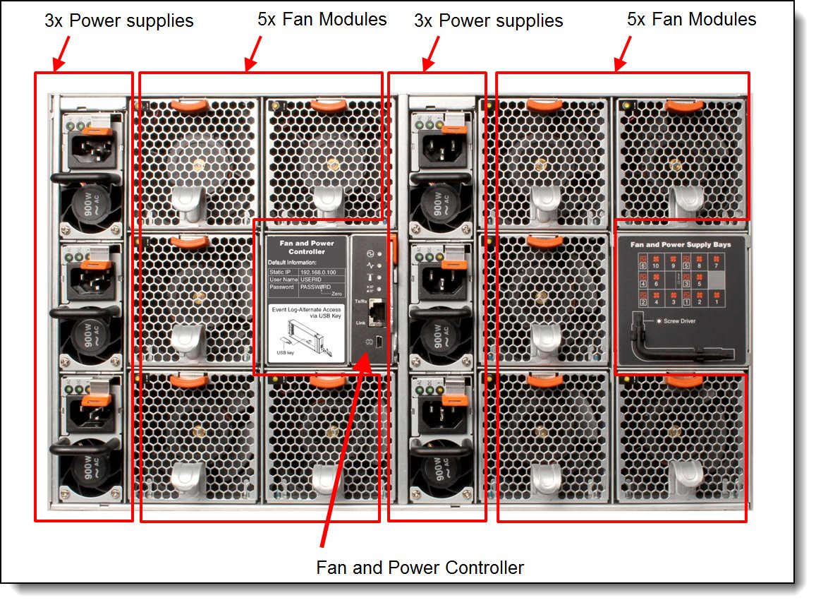
Figure 5. Rear view of the NeXtScale n1200 enclosure
Standard specifications - nx360 M5
The following table lists the standard specifications of the NeXtScale nx360 M5 compute node.
| Components | Specification |
|---|---|
| Machine type | 5465 |
| Firmware | Lenovo-signed firmware |
| Form factor | Standard server: Half-wide, 1U compute node. With optional Native Expansion Tray (either PCIe Tray or Storage Tray): Half-wide 2U compute node. |
| Supported chassis | NeXtScale n1200 enclosure, 6U high; up to 12 compute nodes per chassis. |
| Processor | Two Intel Xeon Processor E5-2600 v4 series processors; Available processors with between 4 cores and 22 cores, up to 55 MB L3 cache and up to 3.5 GHz core speed. QuickPath Interconnect (QPI) links speed up to 9.6 GTps. Hyper-Threading Technology and Turbo Boost Technology. Intel C612 chipset. |
| Memory | Up to 16 DIMM sockets (8 DIMMs per processor) supporting DDR4 DIMMs up to 2400 MHz memory speeds. Four memory channels per processor (two DIMMs per channel). |
| Memory maximums | RDIMMs: Up to 512 GB memory with 16x 32 GB RDIMMs and two processors. |
| Memory protection | Chipkill (x4 memory options only) and ECC. |
| Disk drive bays | Internal to the nx360 M5 (not front accessible): One 3.5-inch simple-swap SATA or two 2.5-inch simple swap SAS/SATA HDDs or SSDs. Front-accessible bays: Two 2.5-inch hot-swap drive bays (optional, replaces the full-height PCIe slot, only supported if internal drive bays are also 2.5-inch bays); With the addition of the NeXtScale 12G Storage Native Expansion Tray (only supported with internal drive bay, not front accessible drive bays): Adds 7 more 3.5-inch simple-swap drive bays. With the addition of the NeXtScale PCIe 2U Native Expansion Tray (only supported with internal drive bay, not front accessible drive bays): Adds 4 more 2.5-inch hot-swap drive bays. |
| Maximum internal storage | Without any expansion tray attached:
|
| RAID support | Four 6 Gb SATA ports through onboard Intel C612 chipset. No RAID standard. Optional 12 Gb SAS/SATA RAID adapters: ServeRAID M5210 or M1215, both standard with RAID 0 and 1. Optional M5210 upgrades: RAID 5, 50 (zero-cache, or 1 GB non-backed cache, or 1 GB or 2 GB or 4 GB flash-backed cache), RAID 6, 60, FoD performance upgrades; Optional upgrade to M1215 for RAID 5 support (zero-cache). No support for ServeRAID C100 or C105 software RAID. |
| Optical drive bays | No internal bays; use an external USB drive. |
| Tape drive bays | No internal bays. Use an external USB drive. |
| Network interfaces | Integrated two-port Gigabit Ethernet (Broadcom BCM5717) with RJ45 connectors. One port dedicated for use by the operating system, and one configurable either as shared by the operating system and Integrated Management Module (IMM) or as dedicated to the operating system. Optional third GbE port for dedicated IMM access. Optionally, PCIe and Mezzanine LOM Gen 2 (ML2) adapters may be added to provide additional network interfaces. ML2 Ethernet adapters support shared access to the IMM. |
| PCI Expansion slots | nx360 M5 without PCIe Native Expansion Tray:
|
| Ports | Front of the server: KVM connector; with the addition of a console breakout cable (1 cable standard with the chassis) supplies one RS232 serial port, one VGA port, and two USB 1.1 ports for local console connectivity. Two 1 Gbps Ethernet ports with RJ45 connectors. Optional third GbE port for dedicated IMM2 access. Internal: One internal USB port for VMware ESXi hypervisor key. Optional support for SD Media Adapter for VMware vSphere hypervisor. |
| Cooling | Supplied by the NeXtScale n1200 enclosure. |
| Power supply | Supplied by the NeXtScale n1200 enclosure. |
| Systems management | UEFI, Integrated Management Module II (IMM2.1) with Renesas SH7758 controller, Predictive Failure Analysis, Light Path Diagnostics, Automatic Server Restart, and ServerGuide. IMM2 upgrades are available to IMM2 Standard and IMM2 Advanced for web GUI and remote presence features. Lenovo XClarity Administrator support. |
| Video | Matrox G200eR2 video core with 16 MB DDR3 video memory that is integrated into the IMM2. Maximum resolution is 1600x1200 with 16M colors (32 bpp) at 75 Hz, or 1680x1050 with 16M colors at 60 Hz. |
| Security | Power-on password, administrator's password, and Trusted Platform Module (TPM) 1.2 or 2.0 (TPM 2.0 requires UEFI 2.21 or later). |
| Operating systems supported | Microsoft Windows Server, Red Hat Enterprise Linux, SUSE Linux Enterprise Server, VMware ESXi. See the Operating system support section for specifics. |
| Limited warranty | Three-year customer-replaceable unit and onsite limited warranty with 9x5/NBD. |
| Service and support | Optional service upgrades are available through Lenovo Services: 4-hour or 2-hour response time, 8-hour fix time, 1-year or 2-year warranty extension, remote technical support for hardware and some Lenovo and OEM software. |
| Dimensions | Width: 216 mm (8.5 in.), height: 41 mm (1.6 in.), depth: 659 mm (25.9 in.) |
| Weight | Maximum weight: 6.17 kg (13.6 lb) |
Standard specifications - n1200 enclosure
The following table lists the standard specifications of the and NeXtScale n1200 enclosure.
| Components | Specification |
|---|---|
| Machine type | 5456 |
| Firmware | With first generation Fan and Power Controller: IBM-signed firmware With second generation Fan and Power Controller: Lenovo-signed firmware |
| Form factor | 6U rack-mounted chassis. |
| Maximum number of servers supported | Up to 12 compute nodes per chassis. |
| Servers per 42U rack | Up to 72 servers in six 6U chassis (36U total, leaving space for top-of-rack switches, UPS units, and so on) |
| Midplane | Passive midplane provides connections to the 12 servers in the front to the power supplies and fans at the rear. Provides signals to control fan speed, power consumption, and node throttling as needed. |
| Fan and Power Controller | The FPC module is the management device for the chassis. Provides integrated systems management functions and controls the power and cooling features of the enclosure. Hot-swappable. Browser and CLI-based user interfaces for remote access via the dedicated 10/100 Mbps Ethernet port. Internal USB memory key for logging and configuration data. |
| Ports | RJ45 port on the rear of the chassis for 10/100 Ethernet connectivity to the FPC for power and cooling management. Each server has RJ45 Ethernet connectors as well as a KVM connector for USB, video and serial connections. |
| I/O architecture | None integrated. Use top-of-rack networking and storage switches. |
| Power supplies | Up to six hot-swap power supplies either 900 W or 1300 W or 1500 W. The 900 W power supplies can operate at 200 V – 240 V or 100 V – 127 V. The 1300 W and 1500 W power supplies operate at 200 V – 240 V only. Power supplies installed at the rear of the chassis. Single power domain supplies power to all servers. Optional redundancy (N+1 or N+N) and oversubscription. Integrated 2500 RPM fan. 80 PLUS Platinum or 80 PLUS Titanium certified, depending on the power supply selected. Built-in overload and surge protection. |
| Cooling | 10 hot-swap dual-rotor 80 mm system fans with tool-less design. |
| System LEDs | FPC LEDs: Power, Activity, Locator, System error log, Ethernet port LEDs. Power supply LEDs: AC power, DC power, Fault LEDs. Servers have more LEDs. |
| Security features | Login password for remote connection. Secure Sockets Layer (SSL) security for remote management access. Supports LDAP for authorization. Trusted and signed firmware. |
| Systems management | Browser-based chassis management through an Ethernet port on the FPC at the rear of the enclosure. Servers provide more management features. |
| Temperature | Operating air temperature:
|
| Electrical power | 1300 W & 1500 W power supplies: 200 V - 240 V ac input (nominal), 50 or 60 Hz 900 W power supplies: 100 V - 127V or 200 V - 240 V ac input (nominal), 50 or 60 Hz |
| Power consumption | 7,800 W maximum |
| Power cords | One AC power cord for each power supply, 1.5 m 10 A, IEC320 C14 to C13 |
| Limited warranty | Three-year customer-replaceable unit and onsite limited warranty with 9x5/NBD. |
| Dimensions | Width: 447 mm (17.6 in.), height: 263 mm (10.4 in.), depth: 915 mm (36 in.). |
| Weight | Fully configured (stand-alone): 112 kg (247 lb), empty chassis 28 kg (62 lb). |
Standard nx360 M5 models
The following table lists the standard models of the NeXtScale nx360 M5
Withdrawn from marketing: The models covered in this product guide are now withdrawn from marketing. The replacement system is the ThinkSystem SD530 which is described in https://lenovopress.com/lp0635.
Memory speeds: All models ship with TruDDR4 memory that is rated at 2400 MHz (as described in the Memory options section), however some models include processors that operate at a lower memory bus speed. As a result, memory installed in those models will operate at a speed that matched the processor, as indicated with parentheses in the Memory column.
Table 3. Standard models
| Model | Intel Xeon Processor† (2 maximum) |
Memory and speed |
RAID controller |
Drive bays | Disks | Network | Optical |
| 5465-23x | 2x E5-2620 v4 8C 2.1GHz 20MB 2133MHz 85W | 2x 8GB (2133 MHz) | 6 Gbps SATA (No RAID) | 1x 3.5-inch SS bay | Open | 2x GbE | None |
| 5465-43x | 2x E5-2650 v4 12C 2.2GHz 30MB 2400MHz 105W | 2x 8GB (2133 MHz) | 6 Gbps SATA (No RAID) | 1x 3.5-inch SS bay | Open | 2x GbE | None |
| 5465-63x | 2x E5-2680 v4 14C 2.4GHz 35MB 2400MHz 120W | 2x 16GB 2400 MHz | 6 Gbps SATA (No RAID) | 2x 2.5-inch SS bays | Open | 2x GbE | None |
† Processor detail: Processor quantity and model, cores, core speed, L3 cache, memory speed, and power consumption.
The nx360 M5 servers are shipped with the following items:
- Statement of Limited Warranty
- Important Notices
- Documentation flyer that contains the Installation and Service Guide
For information about the standard features of the server, see the "Standard specifications" section.
Standard n1200 Enclosure models
The NeXtScale nx360 M5 is supported in the NeXtScale n1200 Enclosure. The standard n1200 Enclosure models are listed in the following table.
Withdrawn from marketing: The models covered in this product guide are now withdrawn from marketing. The replacement system is the ThinkSystem SD530 which is described in https://lenovopress.com/lp0635.
Table 4. Standard enclosure models
| Model | Fan & Power Controller |
Fans (standard / max) |
Power (standard / max) |
| 5456-B2x | FPC2 (Lenovo-signed firmware) | 10x 80mm / 10 | 6x 900 W / 6 |
| 5456-B3x | FPC2 (Lenovo-signed firmware) | 10x 80mm / 10 | 2x 1300 W / 6 |
| 5456-B4x | FPC2 (Lenovo-signed firmware) | 10x 80mm / 10 | 6x 1300 W / 6 |
The chassis ships with these items:
- Rail kit (88Y6763)
- Four detachable chassis lift handles
- One Console breakout cable (also known as a KVM Dongle)
- A Torx-8 (T8) screwdriver for use with components such as drive cages, mounted on the rear of the chassis
- One AC power cord for each power supply that is installed, 1.5m 10A, IEC320 C14 to C13 (part number 39Y7937)
The n1200 provides a shared high-efficiency power supply and fans. Like BladeCenter® and Flex System®, the NeXtScale System compute nodes connect to a midplane, but this connection is for power and control only; the midplane does not provide any I/O connectivity.
NeXtScale n1200 Enclosure support
The NeXtScale nx360 M5 is supported in all models of the NeXtScale n1200 Enclosure listed in the Standard enclosure models table. The number of servers that are supported in each chassis depends on the TDP value of the processors that are used in the servers, the number and capacity of power supplies installed (1300 W or 900 W), and the AC input voltage (100 - 127 V or 200 - 240 V). The following tables use the following conventions:
- A green cell means that the chassis can be filled with servers up to the maximum number that are supported in the chassis (for example, 12 servers without GPU Trays installed, six servers with GPU Trays installed).
- A yellow cell means that the maximum number of servers that the chassis can hold is fewer than the total available bays. Other bays in the chassis must remain empty.
Notes on the tables:
- OVS (Oversubscription) of the power system allows for more efficient use of the available system power. By using oversubscription, users can make the most of the extra power from the redundant power supplies when the power supplies are in healthy condition.
- Oversubscription and Power supply redundancy options are set through one of the available user interfaces to the Fan and Power Controller in the chassis.
- Use the Power Configurator to determine an accurate power model for your configuration, however for 110-120 V AC configurations using the 900 W power supplies, consult Table 24 below for supported numbers of compute nodes.
https://ibm.com/support/entry/portal/docdisplay?lndocid=LNVO-PWRCONF - Some cells indicate two numbers (for example “5 + 1”). This indicates support for a mixture of servers with and without the GPU Tray:
- First number: Number of servers with a GPU Tray attached and two GPUs installed
- Second number: Number of servers without a GPU Tray attached.
For example, “5 + 1” means that the supported combination is five servers with the GPU Tray attached (consuming 10 bays in the chassis), plus one server without a GPU Tray attached (one bay). In such a configuration, 11 bays are consumed and the one remaining server bay in the chassis must remain empty. - The tables are as follows:
- 1500W power supplies and no GPUs
- Table 5 - 1500 W power supplies, 200-240V AC input, no GPUs
- 1500W power supplies with 1U PCIe Native Expansion Tray
- Table 6 - 1500 W power supplies, 200-240V AC input, with two 130 W GPUs
- Table 7 - 1500 W power supplies, 200-240V AC input, with two 225 W GPUs
- Table 8 - 1500 W power supplies, 200-240V AC input, with two 235 W GPUs
- Table 9 - 1500 W power supplies, 200-240V AC input, with two 300 W GPUs
- 1500W power supplies with 2U PCIe Native Expansion Tray
- Table 10 - 1500 W power supplies, 200-240V AC input, with four 130 W GPUs
- Table 11 - 1500 W power supplies, 200-240V AC input, with four 225 W GPUs
- Table 12 - 1500 W power supplies, 200-240V AC input, with four 235 W GPUs
- Table 13 - 1500 W power supplies, 200-240V AC input, with four 300 W GPUs
- 1300W power supplies and no GPUs
- Table 14 - 1300 W power supplies, 200-240V AC input, no GPUs
- 1300W power supplies with 1U PCIe Native Expansion Tray
- Table 15 - 1300 W power supplies, 200-240V AC input, with two 130 W GPUs
- Table 16 - 1300 W power supplies, 200-240V AC input, with two 225 W GPUs
- Table 17 - 1300 W power supplies, 200-240V AC input, with two 235 W GPUs
- Table 18 - 1300 W power supplies, 200-240V AC input, with two 300 W GPUs
- 1300W power supplies with 2U PCIe Native Expansion Tray
- Table 19 - 1300 W power supplies, 200-240V AC input, with four 130 W GPUs
- Table 20 - 1300 W power supplies, 200-240V AC input, with four 225 W GPUs
- Table 21 - 1300 W power supplies, 200-240V AC input, with four 235 W GPUs
- Table 22 - 1300 W power supplies, 200-240V AC input, with four 300 W GPUs
- 900W power supplies
- Table 23 - 900 W power supplies, 200-240V AC input, no GPUs
- Table 24 - 900 W power supplies, 100-127V AC input, no GPUs
- Table 25 - 900 W power supplies, -48 V DC input, no GPUs
- 1500W power supplies and no GPUs
- The use of GPUs requires the PCIe Native Expansion Tray and two processors.
- See the GPU and coprocessor adapters section for information about the power consumption of each supported GPU or coprocessor.
Chassis with six 1500 W power supplies
| CPU TDP | Number of CPUs | Non-redundant or N+1 with OVS | N+1 | N+N | N+N with OVS |
| 55 W | 1 | 12 | 12 | 12 | 12 |
| 2 | 12 | 12 | 12 | 12 | |
| 65 W | 1 | 12 | 12 | 12 | 12 |
| 2 | 12 | 12 | 11 | 12 | |
| 85 W | 1 | 12 | 12 | 12 | 12 |
| 2 | 12 | 12 | 9 | 10 | |
| 90 W | 1 | 12 | 12 | 12 | 12 |
| 2 | 12 | 12 | 8 | 10 | |
| 105 W | 1 | 12 | 12 | 11 | 12 |
| 2 | 12 | 12 | 7 | 9 | |
| 120 W | 1 | 12 | 12 | 10 | 12 |
| 2 | 12 | 11 | 6 | 8 | |
| 135 W | 1 | 12 | 12 | 9 | 11 |
| 2 | 12 | 10 | 6 | 7 | |
| 145 W | 1 | 12 | 12 | 8 | 10 |
| 2 | 12 | 10 | 5 | 7 |
| CPU TDP | Number of CPUs | Non-redundant or N+1 with OVS | N+1 | N+N | N+N with OVS |
| 55 W | 2 | 6 | 6 | 6 | 6 |
| 65 W | 2 | 6 | 6 | 5 + 1 | 6 |
| 85 W | 2 | 6 | 6 | 5 | 6 |
| 90 W | 2 | 6 | 6 | 5 | 6 |
| 105 W | 2 | 6 | 6 | 5 | 6 |
| 120 W | 2 | 6 | 6 | 4 + 1 | 5 + 1 |
| 135 W | 2 | 6 | 6 | 4 | 5 |
| 145 W | 2 | 6 | 6 | 4 | 5 |
| CPU TDP | Number of CPUs | Non-redundant or N+1 with OVS | N+1 | N+N | N+N with OVS |
| 55 W | 2 | 6 | 6 | 4 + 1 | 5 + 1 |
| 65 W | 2 | 6 | 6 | 4 | 5 |
| 85 W | 2 | 6 | 6 | 4 | 5 |
| 90 W | 2 | 6 | 6 | 4 | 5 |
| 105 W | 2 | 6 | 6 | 3 + 1 | 4 + 1 |
| 120 W | 2 | 6 | 6 | 3 + 1 | 4 + 1 |
| 135 W | 2 | 6 | 6 | 3 + 1 | 4 |
| 145 W | 2 | 6 | 6 | 3 + 1 | 4 |
| CPU TDP | Number of CPUs | Non-redundant or N+1 with OVS | N+1 | N+N | N+N with OVS |
| 55 W | 2 | 6 | 6 | 4 + 1 | 5 |
| 65 W | 2 | 6 | 6 | 4 | 5 |
| 85 W | 2 | 6 | 6 | 4 | 5 |
| 90 W | 2 | 6 | 6 | 4 | 4 + 1 |
| 105 W | 2 | 6 | 6 | 3 + 1 | 4 + 1 |
| 120 W | 2 | 6 | 6 | 3 + 1 | 4 + 1 |
| 135 W | 2 | 6 | 6 | 3 + 1 | 4 |
| 145 W | 2 | 6 | 6 | 3 | 4 |
| CPU TDP | Number of CPUs | Non-redundant or N+1 with OVS | N+1 | N+N | N+N with OVS |
| 55 W | 2 | 6 | 6 | 3 + 2 | 4 + 1 |
| 65 W | 2 | 6 | 6 | 3 + 1 | 4 + 1 |
| 85 W | 2 | 6 | 6 | 3 + 1 | 4 |
| 90 W | 2 | 6 | 6 | 3 + 1 | 4 |
| 105 W | 2 | 6 | 5 + 1 | 3 | 4 |
| 120 W | 2 | 6 | 5 + 1 | 3 | 4 |
| 135 W | 2 | 6 | 5 | 3 | 3 + 1 |
| 145 W | 2 | 6 | 5 | 3 | 3 + 1 |
| CPU TDP | Number of CPUs | Non-redundant or N+1 with OVS | N+1 | N+N | N+N with OVS |
| 55 W | 2 | 4 | 4 | 4 | 4 |
| 65 W | 2 | 4 | 4 | 4 | 4 |
| 85 W | 2 | 4 | 4 | 4 | 4 |
| 90 W | 2 | 4 | 4 | 4 | 4 |
| 105 W | 2 | 4 | 4 | 4 | 4 |
| 120 W | 2 | 4 | 4 | 4 | 4 |
| 135 W | 2 | 4 | 4 | 4 | 4 |
| 145 W | 2 | 4 | 4 | 3 + 1 | 4 |
| CPU TDP | Number of CPUs | Non-redundant or N+1 with OVS | N+1 | N+N | N+N with OVS |
| 55 W | 2 | 4 | 4 | 3 + 1 | 4 |
| 65 W | 2 | 4 | 4 | 3 | 3 + 3 |
| 85 W | 2 | 4 | 4 | 3 | 3 + 2 |
| 90 W | 2 | 4 | 4 | 3 | 3 + 2 |
| 105 W | 2 | 4 | 4 | 3 | 3 + 2 |
| 120 W | 2 | 4 | 4 | 2 + 2 | 3 + 1 |
| 135 W | 2 | 4 | 4 | 2 + 2 | 3 + 1 |
| 145 W | 2 | 4 | 4 | 2 + 2 | 3 + 1 |
| CPU TDP | Number of CPUs | Non-redundant or N+1 with OVS | N+1 | N+N | N+N with OVS |
| 55 W | 2 | 4 | 4 | 3 | 3 + 3 |
| 65 W | 2 | 4 | 4 | 3 | 3 + 2 |
| 85 W | 2 | 4 | 4 | 3 | 3 + 2 |
| 90 W | 2 | 4 | 4 | 3 | 3 + 2 |
| 105 W | 2 | 4 | 4 | 2 + 2 | 3 + 1 |
| 120 W | 2 | 4 | 4 | 2 + 2 | 3 + 1 |
| 135 W | 2 | 4 | 4 | 2 + 2 | 3 + 1 |
| 145 W | 2 | 4 | 4 | 2 + 1 | 3 |
| CPU TDP | Number of CPUs | Non-redundant or N+1 with OVS | N+1 | N+N | N+N with OVS |
| 55 W | 2 | 4 | 4 | 2 + 2 | 3 + 1 |
| 65 W | 2 | 4 | 4 | 2 + 2 | 3 |
| 85 W | 2 | 4 | 4 | 2 + 2 | 3 |
| 90 W | 2 | 4 | 4 | 2 + 1 | 3 |
| 105 W | 2 | 4 | 4 | 2 + 1 | 3 |
| 120 W | 2 | 4 | 4 | 2 + 1 | 2 + 3 |
| 135 W | 2 | 4 | 4 | 2 + 1 | 2 + 2 |
| 145 W | 2 | 4 | 4 | 2 + 1 | 2 + 2 |
Chassis with six 1300 W power supplies
| CPU TDP | Number of CPUs | Non-redundant or N+1 with OVS | N+1 | N+N | N+N with OVS |
| 55 W | 1 | 12 | 12 | 12 | 12 |
| 2 | 12 | 12 | 10 | 12 | |
| 65 W | 1 | 12 | 12 | 12 | 12 |
| 2 | 12 | 12 | 9 | 11 | |
| 85 W | 1 | 12 | 12 | 12 | 12 |
| 2 | 12 | 12 | 8 | 10 | |
| 90 W | 1 | 12 | 12 | 12 | 12 |
| 2 | 12 | 12 | 7 | 9 | |
| 105 W | 1 | 12 | 12 | 12 | 12 |
| 2 | 12 | 12 | 7 | 8 | |
| 120 W | 1 | 12 | 12 | 11 | 12 |
| 2 | 12 | 11 | 6 | 8 | |
| 135 W | 1 | 12 | 12 | 11 | 12 |
| 2 | 12 | 10 | 6 | 7 | |
| 145 W | 1 | 12 | 12 | 10 | 12 |
| 2 | 12 | 10 | 5 | 7 |
| CPU TDP | Number of CPUs | Non-redundant or N+1 with OVS | N+1 | N+N | N+N with OVS |
| 55 W | 2 | 6 | 6 | 6 | 6 |
| 65 W | 2 | 6 | 6 | 5 + 1 | 6 |
| 85 W | 2 | 6 | 6 | 5 | 6 |
| 90 W | 2 | 6 | 6 | 5 | 6 |
| 105 W | 2 | 6 | 6 | 5 | 6 |
| 120 W | 2 | 6 | 6 | 4 + 1 | 5 + 1 |
| 135 W | 2 | 6 | 6 | 4 | 5 |
| 145 W | 2 | 6 | 6 | 4 | 5 |
| CPU TDP | Number of CPUs | Non-redundant or N+1 with OVS | N+1 | N+N | N+N with OVS |
| 55 W | 2 | 6 | 6 | 4 + 1 | 5 + 1 |
| 65 W | 2 | 6 | 6 | 4 | 5 |
| 85 W | 2 | 6 | 6 | 4 | 5 |
| 90 W | 2 | 6 | 6 | 4 | 5 |
| 105 W | 2 | 6 | 6 | 3 + 1 | 4 + 1 |
| 120 W | 2 | 6 | 6 | 3 + 1 | 4 + 1 |
| 135 W | 2 | 6 | 6 | 3 + 1 | 4 |
| 145 W | 2 | 6 | 6 | 3 + 1 | 4 |
| CPU TDP | Number of CPUs | Non-redundant or N+1 with OVS | N+1 | N+N | N+N with OVS |
| 55 W | 2 | 6 | 6 | 4 + 1 | 5 |
| 65 W | 2 | 6 | 6 | 4 | 5 |
| 85 W | 2 | 6 | 6 | 4 | 5 |
| 90 W | 2 | 6 | 6 | 4 | 4 + 1 |
| 105 W | 2 | 6 | 6 | 3 + 1 | 4 + 1 |
| 120 W | 2 | 6 | 6 | 3 + 1 | 4 + 1 |
| 135 W | 2 | 6 | 6 | 3 + 1 | 4 |
| 145 W | 2 | 6 | 6 | 3 | 4 |
| CPU TDP | Number of CPUs | Non-redundant or N+1 with OVS | N+1 | N+N | N+N with OVS |
| 55 W | 2 | 6 | 6 | 3 + 2 | 4 + 1 |
| 65 W | 2 | 6 | 6 | 3 + 1 | 4 + 1 |
| 85 W | 2 | 6 | 6 | 3 + 1 | 4 |
| 90 W | 2 | 6 | 6 | 3 + 1 | 4 |
| 105 W | 2 | 6 | 5 + 1 | 3 | 4 |
| 120 W | 2 | 6 | 5 + 1 | 3 | 4 |
| 135 W | 2 | 6 | 5 | 3 | 3 + 1 |
| 145 W | 2 | 6 | 5 | 3 | 3 + 1 |
| CPU TDP | Number of CPUs | Non-redundant or N+1 with OVS | N+1 | N+N | N+N with OVS |
| 55 W | 2 | 4 | 4 | 4 | 4 |
| 65 W | 2 | 4 | 4 | 4 | 4 |
| 85 W | 2 | 4 | 4 | 3 + 1 | 4 |
| 90 W | 2 | 4 | 4 | 3 + 1 | 4 |
| 105 W | 2 | 4 | 4 | 3 + 1 | 4 |
| 120 W | 2 | 4 | 4 | 3 | 4 |
| 135 W | 2 | 4 | 4 | 3 | 4 |
| 145 W | 2 | 4 | 4 | 3 | 4 |
| CPU TDP | Number of CPUs | Non-redundant or N+1 with OVS | N+1 | N+N | N+N with OVS |
| 55 W | 2 | 4 | 4 | 2 + 3 | 3 + 1 |
| 65 W | 2 | 4 | 4 | 2 + 2 | 3 + 1 |
| 85 W | 2 | 4 | 4 | 2 + 2 | 3 |
| 90 W | 2 | 4 | 4 | 2 + 2 | 3 |
| 105 W | 2 | 4 | 4 | 2 + 1 | 3 |
| 120 W | 2 | 4 | 4 | 2 + 1 | 3 |
| 135 W | 2 | 4 | 4 | 2 + 1 | 3 |
| 145 W | 2 | 4 | 4 | 2 + 1 | 2 + 2 |
| CPU TDP | Number of CPUs | Non-redundant or N+1 with OVS | N+1 | N+N | N+N with OVS |
| 55 W | 2 | 4 | 4 | 2 + 2 | 3 + 1 |
| 65 W | 2 | 4 | 4 | 2 + 2 | 3 + 1 |
| 85 W | 2 | 4 | 4 | 2 + 1 | 3 |
| 90 W | 2 | 4 | 4 | 2 + 1 | 3 |
| 105 W | 2 | 4 | 4 | 2 + 1 | 3 |
| 120 W | 2 | 4 | 4 | 2 + 1 | 3 |
| 135 W | 2 | 4 | 4 | 2 + 1 | 2 + 2 |
| 145 W | 2 | 4 | 4 | 2 | 2 + 2 |
| CPU TDP | Number of CPUs | Non-redundant or N+1 with OVS | N+1 | N+N | N+N with OVS |
| 55 W | 2 | 4 | 3 + 3 | 2 + 1 | 2 + 3 |
| 65 W | 2 | 4 | 3 + 3 | 2 | 2 + 3 |
| 85 W | 2 | 4 | 3 + 2 | 2 | 2 + 2 |
| 90 W | 2 | 4 | 3 + 2 | 2 | 2 + 2 |
| 105 W | 2 | 4 | 3 + 2 | 2 | 2 + 2 |
| 120 W | 2 | 4 | 3 + 1 | 2 | 2 + 1 |
| 135 W | 2 | 4 | 3 + 1 | 2 | 2 + 1 |
| 145 W | 2 | 4 | 3 + 1 | 2 | 2 + 1 |
Chassis with six 900 W power supplies
| CPU TDP | Number of CPUs | Non-redundant or N+1 with OVS | N+1 | N+N | N+N with OVS |
| 55 W | 1 | 12 | 12 | 11 | 12 |
| 2 | 12 | 11 | 6 | 8 | |
| 65 W | 1 | 12 | 12 | 10 | 12 |
| 2 | 12 | 10 | 6 | 7 | |
| 85 W | 1 | 12 | 12 | 9 | 11 |
| 2 | 11 | 9 | 5 | 6 | |
| 90 W | 1 | 12 | 12 | 9 | 11 |
| 2 | 11 | 9 | 5 | 6 | |
| 105 W | 1 | 12 | 12 | 8 | 10 |
| 2 | 10 | 8 | 4 | 5 | |
| 120 W | 1 | 12 | 12 | 7 | 9 |
| 2 | 9 | 7 | 4 | 5 | |
| 135 W | 1 | 12 | 12 | 7 | 9 |
| 2 | 8 | 7 | 4 | 5 | |
| 145 W | 1 | 12 | 12 | 7 | 8 |
| 2 | 8 | 6 | 3 | 4 |
| CPU TDP | Number of CPUs | Non-redundant or N+1 with OVS | N+1 | N+N | N+N with OVS |
| 55 W | 1 | 12 | 12 | 6 | 8 |
| 2 | 9 | 7 | 4 | 5 | |
| 65 W | 1 | 12 | 11 | 6 | 8 |
| 2 | 8 | 6 | 3 | 4 | |
| 85 W | 1 | 12 | 10 | 5 | 7 |
| 2 | 7 | 6 | 3 | 4 | |
| 90 W | 1 | 12 | 10 | 5 | 7 |
| 2 | 7 | 5 | 3 | 4 | |
| 105 W | 1 | 11 | 9 | 5 | 6 |
| 2 | 6 | 5 | 2 | 3 | |
| 120 W | 1 | 10 | 8 | 4 | 6 |
| 2 | 6 | 4 | 2 | 3 | |
| 135 W | 1 | 10 | 8 | 4 | 5 |
| 2 | 5 | 4 | 2 | 3 | |
| 145 W | 1 | 9 | 7 | 4 | 5 |
| 2 | 5 | 4 | 2 | 3 |
| CPU TDP | Number of CPUs | Non-redundant or N+1 with OVS | N+1 | N+N | N+N with OVS |
| 55 W | 1 | 12 | 12 | 11 | 12 |
| 2 | 12 | 11 | 6 | 8 | |
| 65 W | 1 | 12 | 12 | 10 | 12 |
| 2 | 12 | 10 | 6 | 7 | |
| 85 W | 1 | 12 | 12 | 9 | 11 |
| 2 | 11 | 9 | 5 | 6 | |
| 90 W | 1 | 12 | 12 | 9 | 11 |
| 2 | 11 | 9 | 5 | 6 | |
| 105 W | 1 | 12 | 12 | 8 | 10 |
| 2 | 10 | 8 | 4 | 5 | |
| 120 W | 1 | 12 | 12 | 7 | 9 |
| 2 | 9 | 7 | 4 | 5 | |
| 135 W | 1 | 12 | 12 | 7 | 9 |
| 2 | 8 | 7 | 4 | 5 | |
| 145 W | 1 | 12 | 12 | 7 | 8 |
| 2 | 8 | 6 | 3 | 4 |
Processor options
The nx360 M5 supports the processor options that are listed in the following table.
Note: This product guide covers the NeXtScale nx360 M4 with E5 v4 processors. For information about the server with v3 processor support, see the nx360 M5 (E5-2600 v3) Product Guide at https://lenovopress.com/tips1195.
| Part number |
Feature code* | Intel Xeon processors** | Where used |
|---|---|---|---|
| 00YE725 | ATJ3 / ATJP | Intel Xeon Processor E5-2603 v4 6C 1.7GHz 15MB Cache 1866MHz 85W | - |
| 00YE724 | ATJ2 / ATJN | Intel Xeon Processor E5-2609 v4 8C 1.7GHz 20MB Cache 1866MHz 85W | - |
| 00YE723 | ATJ1 / ATJM | Intel Xeon Processor E5-2620 v4 8C 2.1GHz 20MB Cache 2133MHz 85W | 23x |
| 00YE729 | ATJ7 / ATJT | Intel Xeon Processor E5-2623 v4 4C 2.6GHz 10MB Cache 2133MHz 85W | - |
| 00YE722 | ATJ0 / ATJL | Intel Xeon Processor E5-2630 v4 10C 2.2GHz 25MB Cache 2133MHz 85W | - |
| 00YE731 | ATJ9 / ATJV | Intel Xeon Processor E5-2630L v4 10C 1.8GHz 25MB Cache 2133MHz 55W | - |
| 00YE728 | ATJ6 / ATJS | Intel Xeon Processor E5-2637 v4 4C 3.5GHz 15MB Cache 2400MHz 135W | - |
| 00YE721 | ATHZ / ATJK | Intel Xeon Processor E5-2640 v4 10C 2.4GHz 25MB Cache 2133MHz 90W | - |
| 00YE727 | ATJ5 / ATJR | Intel Xeon Processor E5-2643 v4 6C 3.4GHz 20MB Cache 2400MHz 135W | - |
| 00YE720 | ATHY / ATJJ | Intel Xeon Processor E5-2650 v4 12C 2.2GHz 30MB Cache 2400MHz 105W | 43x |
| 00YE730 | ATJ8 / ATJU | Intel Xeon Processor E5-2650L v4 14C 1.7GHz 35MB Cache 2400MHz 65W | - |
| 00YE719 | ATHX / ATJH | Intel Xeon Processor E5-2660 v4 14C 2.0GHz 35MB Cache 2400MHz 105W | - |
| 00YE726 | ATJ4 / ATJQ | Intel Xeon Processor E5-2667 v4 8C 3.2GHz 25MB Cache 2400MHz 135W | - |
| 00YE718 | ATHW / ATJG | Intel Xeon Processor E5-2680 v4 14C 2.4GHz 35MB Cache 2400MHz 120W | 63x |
| 00YE716 | ATHU / ATJE | Intel Xeon Processor E5-2683 v4 16C 2.1GHz 40MB Cache 2400MHz 120W | - |
| 00YE717 | ATHV / ATJF | Intel Xeon Processor E5-2690 v4 14C 2.6GHz 35MB Cache 2400MHz 135W | - |
| 00YE715 | ATHT / ATJD | Intel Xeon Processor E5-2695 v4 18C 2.1GHz 45MB Cache 2400MHz 120W | - |
| 00YE714 | ATHS / ATJC | Intel Xeon Processor E5-2697 v4 18C 2.3GHz 45MB Cache 2400MHz 145W | - |
| 00YK422 | AUEG / AUEH | Intel Xeon Processor E5-2697A v4 16C 2.6GHz 40MB Cache 2400MHz 145W | - |
| 00YE713 | ATHR / ATJB | Intel Xeon Processor E5-2698 v4 20C 2.2GHz 50MB Cache 2400MHz 135W | - |
| 00YE712 | ATHQ / ATJA | Intel Xeon Processor E5-2699 v4 22C 2.2GHz 55MB Cache 2400MHz 145W | - |
| 00YD131 | AVH5 / AVHD | Intel Xeon Processor E5-2699A v4 22C 2.4GHz 55MB Cache 2400MHz 145W | - |
| 00YD132 | AVH4 / AVHC | Intel Xeon Processor E5-2699R v4 22C 2.2GHz 55MB Cache 2400MHz 145W | - |
* The first feature code corresponds to the first processor; the second feature code corresponds to the second processor.
** Processor detail: Model, core count, core speed, L3 cache, memory speed, and TDP power.
Memory options
TruDDR4 Memory uses the highest quality components that are sourced from Tier 1 DRAM suppliers and only memory that meets the strict requirements of Lenovo is selected. It is compatibility tested and tuned on every System x server to maximize performance and reliability. TruDDR4 Memory has a unique signature that is programmed into the DIMM that enables System x servers to verify whether the memory installed is qualified/supported by Lenovo.
Because TruDDR4 Memory is authenticated, certain extended memory performance features can be enabled to extend performance over industry standards. From a service and support standpoint, memory automatically assumes the Lenovo system warranty, and Lenovo provides service and support worldwide.
The NeXtScale nx360 M5 supports up to eight TruDDR4 Memory DIMMs when one processor is installed and up to 16x DIMMs when two processors are installed. Each processor has four memory channels, and there are two DIMMs per memory channel (2 DPC). UDIMMs are not supported.
The following table lists the memory options that are available for the nx360 M5 server.
| Part number |
Feature code |
Description | Maximum supported |
Models where used |
|---|---|---|---|---|
| RDIMMs | ||||
| 46W0821 | ATC8 | 8GB TruDDR4 Memory (1Rx4, 1.2V) PC4-19200 CL17 2400MHz LP RDIMM | 16 | - |
| 46W0825 | ATC9 | 8GB TruDDR4 Memory (2Rx8, 1.2V) PC4-19200 CL17 2400MHz LP RDIMM | 16 | 23x, 43x |
| 46W0829 | ATCA | 16GB TruDDR4 Memory (2Rx4, 1.2V) PC4-19200 CL17 2400MHz LP RDIMM | 16 | 63x |
| 01KN301 | AVP0 | 16GB TruDDR4 Memory (2Rx8, 1.2V) PC4-19200 CL17 2400MHz LP RDIMM | 16 | - |
| 46W0833 | ATCB | 32GB TruDDR4 Memory (2Rx4, 1.2V) PC4-19200 CL17 2400MHz LP RDIMM | 16 | - |
In the nx360 M5, the maximum memory speed of a configuration is the lower of the following two values:
- The memory speed of the processor
- The memory speed of the DIMM
The following table shows the maximum memory speeds that are achievable. The table also shows the maximum memory capacity at any speed that is supported by the DIMM and the maximum memory capacity at the rated DIMM speed.
In the table, cells that are highlighted in gray indicate when the specific combination of DIMM voltage and number of DIMMs per channel still allows the DIMMs to operate at the rated speed.
| Specification |
RDIMMs
|
|
| Rank | Single rank | Dual rank |
| Part numbers | 46W0821 (8 GB) | 46W0825 (8 GB) 46W0829 (16 GB) 46W0833 (32 GB) |
| Rated speed | 2400 MHz | 2400 MHz |
| Rated voltage | 1.2 V | 1.2 V |
| Operating voltage | 1.2 V | 1.2 V |
| Maximum quantity* | 16 | 16 |
| Largest DIMM | 8 GB | 32 GB |
| Max memory capacity | 128 GB | 512 GB |
| Max memory at rated speed | 128 GB | 512 GB |
| Maximum operating speed (MHz) | ||
| One DIMM per channel | 2400 MHz | 2400 MHz |
| Two DIMMs per channel | 2400 MHz† | 2400 MHz† |
* The maximum quantity that is supported is shown for two processors that are installed. When one processor is installed, the maximum quantity that is supported is half of that shown.
† This speed is above the Intel standard and is achieved only when Lenovo TruDDR4 memory is used
The following memory protection technologies are supported:
- ECC
- Memory mirroring
- Memory sparing
If memory mirroring is used, DIMMs must be installed in pairs (minimum of one pair per CPU), and both DIMMs in a pair must be identical in type and size.
If memory rank sparing is used, a minimum of one quad-rank DIMM or two single-rank or dual-rank DIMMs must be installed per populated channel (the DIMMs do not need to be identical). In rank sparing mode, one rank of a DIMM in each populated channel is reserved as spare memory. The size of a rank varies depending on the DIMMs that are installed.
NeXtScale 12G Storage Native Expansion Tray
The NeXtScale 12G Storage Native Expansion Tray is a half-wide 1U expansion tray that attaches to the nx360 M5 to provide up to seven extra 3.5-inch simple-swap drives. The tray allows the configuration of storage-rich nx360 M5 compute nodes.
Note: The 12G Storage Native Expansion Tray and the PCIe Native Expansion Tray cannot be connected to the same compute node.
The following figure shows the storage tray attached to an nx360 M5 compute node.
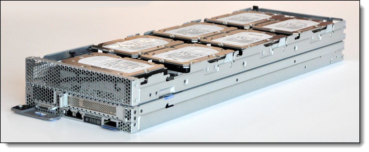
Figure 6. NeXtScale 12G Storage Native Expansion Tray attached to an nx360 M5 compute node
Ordering information is listed in the following table.
Table 29. Ordering information
| Part number | Feature code | Description |
| 00KG601 | ASGR | NeXtScale 12G Storage Native Expansion Tray |
When the NeXtScale 12G Storage Native Expansion Tray is used, one of the following disk controller adapters must be installed in the front PCIe slot (slot 1) in the nx360 M5:
- ServeRAID M5210 SAS/SATA Controller for System x, 46C9110
- ServeRAID M1215 SAS/SATA Controller for System x, 46C9114
- N2215 SAS/SATA HBA for System x, 47C8675
No additional PCIe adapter is allowed for selection. The ML2 slot is still available.
Internal storage
The NeXtScale nx360 M5 server supports the following drives:
Internal drives:
- One 3.5-inch simple-swap HDD, or
- Four 2.5-inch HDDs or SSDs (two simple-swap and two hot-swap)
Note: The server supports four 1.8-inch simple-swap SSDs, however all 1.8-inch drives are now withdrawn from marketing.
In addition, with optional expansion trays:
- Seven additional 3.5-inch simple-swap HDDs with the use of the NeXtScale 12G Storage Native Expansion Tray, or
- Four additional 2.5-inch hot-swap HDDs or SSDs with the use of the PCIe 2U Native Expansion Tray
Internal simple-swap drives
The NeXtScale nx360 M5 server supports the following internal drives to be installed at the rear of the server:
- Up to one 3.5-inch simple-swap HDD, or
- Up to two 2.5-inch simple-swap HDDs or SSDs
Use of 3.5-inch 12Gb SAS and NL SAS drives: A 3.5-inch SAS and NL SAS drive is supported installed internally to the server only when the NeXtScale 12G Storage Native Expansion Tray is used. Without the NeXtScale 12G Storage Native Expansion Tray, the only 3.5-inch drives supported in the server are SATA or NL SATA drives.
Use of 2.5-inch SAS and NL SAS drives: 2.5-inch SAS drives are not supported in the internal (non-hot-swap) drive bays of the server if the 12G Storage Native Expansion Tray is attached.
The following figure shows the two available variations (1.8-inch drives are now withdrawn). These drives are installed internally in the server; to replace them the server must be powered down and removed from the n1200 enclosure.
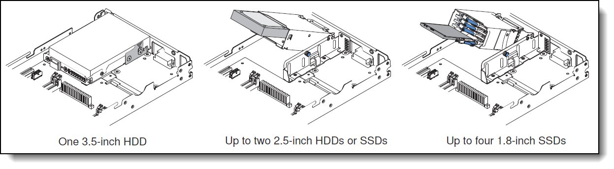
Figure 7. Drive bay options
These internal drives are installed in a drive cage. Ordering information for these drive cages are listed in the following table.
| Part number | Feature code | Description | Models where used |
| 00KA894 | A5V2 | nx360 M5 2.5" Rear Drive Cage | 63x |
| 00FL465 | A5K1 | nx360 M5 3.5" Rear Drive Cage | 23x, 43x |
| 00KG603 | ASGS | nx360 3.5" HDD8 Cage - HW RAID* | - |
* This single 3.5-inch drive cage is installed in the nx360 M5 when you have the 12G Storage Native Expansion Tray attached and want to configure all eight 3.5-inch drives as one RAID array using separate RAID adapter.
Hot-swap drives
In addition, if the internal drives are 2.5-inch drive bays (or if no internal drive bay is selected), then the server also supports two additional 2.5-inch drive bays. These are front accessible and are hot-swap drive bays. These hot-swap drive bays take the place of the full-height PCIe slot, as shown in the following figure.
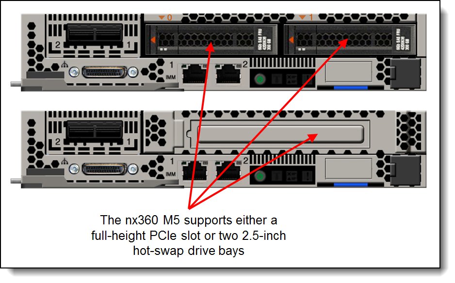
Figure 8. NeXtScale nx360 M5 configurations - hot-swap 2.5-inch drive bays or full-height PCIe slot
The following table shows the ordering information for the two 2.5-inch hot-swap drive bays.
Table 31. Drive cage for the hot-swap drive bay in the nx360 M5
| Part number | Feature code | Description | Models where used |
| 00FL175 | A5NA | nx360 M5 2.5" Front Hot Swap Drive Cage | - |
Note: Neither the 12G Storage Native Expansion Tray nor the PCIe 2U Native Expansion Tray can be used with the nx360 M5 2.5” Front Hot Swap Drive Cage
NeXtScale 12G Storage Native Expansion Tray
In addition to the drive bays internal to the server, the nx360 M5 supports seven additional 3.5-inch drive bays if the NeXtScale 12G Storage Native Expansion Tray is attached. The 12G Storage Native Expansion Tray can be used with any of the above four bay configurations to provide the following internal drive combinations:
- Up to eight 3.5-inch simple-swap SATA, NL SATA or NL SAS drives
- Up to seven 3.5-inch simple-swap SATA, NL SATA or NL SAS drives and two 2.5-inch simple-swap SATA drives
- Up to seven 3.5-inch simple-swap SATA, NL SATA or NL SAS drives and four 1.8-inch simple-swap SATA SSDs
Drives that are used in the 12G Storage Native Expansion Tray do not need a cage.
There are two 3.5-inch drive cages (part numbers 00FL465 and 00KG603 in the last two rows of Table 30). If the 12G Storage Native Expansion Tray is attached to the nx360 M5, then the usage of the RAID cage (feature ASGS, option 00KG603) allows you to configure a RAID array that spans all eight drives, that is, the seven in the storage tray and the one drive internal to the nx360 M5. Such a configuration is connected either to a RAID adapter or SAS HBA; the usage of the internal SATA ports is not supported with this RAID cage.
If the 3.5-inch HDD cage (feature A5K1) is used, then a RAID array can be formed only with the seven drives in the storage tray. In such a configuration, the drives in the storage tray are connected either to RAID adapter or SAS HBA, and the single drive in the nx360 M5 is connected to an onboard SATA port.
These use of the storage tray requires a RAID controller or SAS HBA installed in the PCIe slot at the front of the server. The use a controller installed in the dedicated RAID slot at the rear of the server is not supported.
NeXtScale PCIe 2U Native Expansion Tray
As an alternative to the Storage Native Expansion Tray, the PCIe 2U Native Expansion Tray offers up to 4 additional 2.5-inch hot-swap drive bays beyond the bays internal to the server. The following drive combinations are supported:
- One 3.5-inch simple-swap SATA, NL SATA or NL SAS drive (internal) and up to four 2.5-inch hot-swap SAS/SATA drives (expansion tray)
- Two 2.5-inch simple-swap SATA drives (internal) and up to four 2.5-inch hot-swap SAS/SATA drives (expansion tray)
- Four 1.8-inch simple-swap SATA SSDs (internal) and up to four 2.5-inch hot-swap SAS/SATA drives (expansion tray)
The use of the four 2.5-inch hot-swap drive bays in the expansion tray require an optional backplane as listed in the following table.
Table 32. Backplane for the hot-swap drive bays in the PCIe 2U Native Expansion Tray
| Part number | Feature code | Description | Models where used |
| 44X4104 | A4A6 | 4x 2.5" HDD Riser (Backplane and SAS cable) | - |
These drive bays in the require a RAID controller or SAS HBA installed in the dedicated RAID slot at rear of the server.
For more information see the NeXtScale PCIe 2U Native Expansion Tray section.
Controllers for internal storage
The onboard SATA controller (integrated into the Intel C612 chipset) supports any of the following drive configurations:
- One 3.5-inch simple-swap SATA or NL SATA drive
- Up to two 2.5-inch simple-swap NL SATA drives
- Up to four 1.8-inch SATA Enterprise Value SSDs
The following drive combinations may be used instead with a RAID controller or SAS/SATA HBA that is installed in the internal RAID adapter riser slot:
- Up to two 2.5-inch simple-swap NL SATA drives
- Up to four 1.8-inch SATA Enterprise Value SSDs
Any of the following drive configurations require a RAID controller or SAS/SATA HBA that is installed in the internal RAID adapter riser slot:
- A 3.5-inch SAS or NL SAS simple-swap drive installed in the server
- Up to two 2.5-inch simple-swap SAS drives
- Up to two 2.5-inch hot-swap drives (installed in the front drive bays)
- Up to two 2.5-inch simple-swap SAS drives plus up to four 2.5-inch hot-swap drives installed in the PCIe 2U Native Expansion Tray.
The supported RAID controller or SAS/SATA host bus adapter is installed in a dedicated RAID adapter slot, through a riser card, at the rear of the server that is adjacent to the internal drive bays. Installation of the adapter is shown in the following figure.

Figure 9. RAID controller and RAID riser card installation
When the NeXtScale 12G Storage Native Expansion Tray is used, the RAID controller or SAS/SATA host bus adapter must be installed in the front PCIe slot (slot 1) in the nx360 M5. The installed drives are connected as follows:
- The 3.5-inch drives in the storage tray are connected to the RAID controller or HBA
- If installed, any 1.8-inch and 2.5-inch simple-swap rear drives in the nx360 M5 are connected to the onboard SATA controller
- If a 3.5-inch SATA or NL SATA drive is used in the server, it may be either connected to the on board SATA controller or to the RAID controller or HBA.
- If a 3.5-inch SAS or NL SAS drive is used in the server, it is connected to the RAID controller or HBA
The following table lists the RAID controllers and HBAs that are used for internal disk storage of the nx360 M5 server and the Riser card that is needed to install the adapter.
| Part number |
Feature code |
Description | Maximum supported |
| Riser card for RAID adapter | |||
| 00FL179 | A5JZ | nx360 M5 RAID Riser | 1 |
| RAID Controllers and SAS Host Bus Adapters | |||
| 46C9110 | A3YZ | ServeRAID M5210 SAS/SATA Controller for System x | 1* |
| 46C9114 | A45W | ServeRAID M1215 SAS/SATA Controller for System x | 1* |
| 47C8675 | A3YY | N2215 SAS/SATA HBA for System x | 1* |
| Hardware upgrades - ServeRAID M5210 | |||
| 47C8656 | A3Z0 | ServeRAID M5200 Series 1GB Cache/RAID 5 Upgrade-FoD | 1 |
| 47C8660 | A3Z1 | ServeRAID M5200 Series 1GB Flash/RAID 5 Upgrade-FoD | 1 |
| 47C8664 | A3Z2 | ServeRAID M5200 Series 2GB Flash/RAID 5 Upgrade-FoD | 1 |
| 47C8668 | A3Z3 | ServeRAID M5200 Series 4GB Flash/RAID 5 Upgrade-FoD | 1 |
| Features on Demand Upgrades - ServeRAID M5210 | |||
| 47C8706 | A3Z5 | ServeRAID M5200 Series RAID 6 Upgrade-FoD | 1 |
| 47C8708 | A3Z6 | ServeRAID M5200 Series Zero Cache/RAID 5 Upgrade-FoD | 1 |
| 47C8710 | A3Z7 | ServeRAID M5200 Series Performance Accelerator-FoD | 1 |
| 47C8712 | A3Z8 | ServeRAID M5200 Series SSD Caching Enabler-FoD | 1 |
| Features on Demand Upgrades - ServeRAID M1215 | |||
| 00AE930 | A5H5 | ServeRAID M1200 Zero Cache/RAID 5 Upgrade FOD | 1 |
* Mutually exclusive. Only one of these adapters is supported in the nx360 M5 and it requires RAID Riser 00FL179 when installed in the internal RAID slot.
Controller specifications
The ServeRAID M5210 SAS/SATA Controller has the following specifications:
- Eight internal 12 Gbps SAS/SATA ports
- 12 Gbps throughput per port
- Based on the LSI SAS3108 12 Gbps ROC controller
- Two mini-SAS HD internal connectors (SFF8643)
- Supports connections to SAS/SATA drives and SAS Expanders
- Supports RAID levels 0, 1, and 10
- Supports RAID levels 5 and 50 with optional M5200 Series RAID 5 upgrades
- Supports RAID 6 and 60 with the optional M5200 Series RAID 6 Upgrade
- Supports 1 GB cache (no battery backup) or 1 GB or 2 GB flash-backed cache
- Supports performance upgrades through Features on Demand
The ServeRAID M1215 SAS/SATA Controller has the following specifications:
- Eight internal 12 Gbps SAS/SATA ports
- Up to 12 Gbps throughput per port
- Two internal mini-SAS HD connectors (SFF8643)
- Based on the LSI SAS3008 12 Gbps RAID on Chip (ROC) controller
- Support for RAID levels 0, 1, and 10 standard; support for RAID 5 and 50 with optional FoD upgrade
- Zero Controller Cache, no battery/flash backup
- Optional support for self-encrypting drives (SEDs) with MegaRAID SafeStore (with RAID 5 upgrade)
- Fixed stripe size of 64 KB
For more information, see the list of Lenovo Press Product Guides in the RAID adapters category:
https://lenovopress.com/servers/options/raid
The N2215 SAS/SATA HBA has the following specifications:
- Eight internal 12 Gbps SAS/SATA ports (support for 12, 6, or 3 Gbps SAS speeds and 6 or 3 Gbps SATA speeds)
- Up to 12 Gbps throughput per port
- Two internal x4 HD Mini-SAS connectors (SFF-8643)
- Based on the LSI SAS3008 12 Gbps controller
- Non-RAID (JBOD mode) support for SAS and SATA HDDs and SSDs (RAID not supported)
- PCI low profile, half-length - MD2 form factor
- PCI Express 3.0 x8 host interface
- Optimized for SSD performance
- High-performance IOPS LSI Fusion-MPT architecture
- Advanced power management support
- Support for SSP, SMP, STP, and SATA protocols
- End-to-End CRC with Advanced Error Reporting
- T-10 Protection Model for early detection of and recovery from data corruption
- Spread Spectrum Clocking for EMI reductions
For more information about this SAS/SATA HBA, see the list of Lenovo Press Product Guides in the host bus adapters category:
https://lenovopress.com/servers/options/hba
The following table lists the SAS/SATA cables supported for connection from the onboard SATA controller, RAID controller or SAS/SATA HBA to the various drive cages.
Note: The 4x 2.5" backplane option (44X4104) for the NeXtScale PCIe 2U Native Expansion Tray includes the SAS cable needed to connect the backplane to the RAID controller.
| Part number |
Feature code |
Description |
| 00FL170 | A5K3 | nx360 M5 1x2, 2.5” 12G HDD short cable, HW RAID (stack-up) |
| 00FL173* | A5K7 | nx360 M5 1.8” SSD 12G short cable vertical (HW RAID) |
| 00KA360 | A5QH | nx360 M5 1x2, 2.5” 12G HDD short cable, HW RAID (stack-up) Port 1 |
| 00FL466 | A5K4 | nx360 M5 2.5” HDD 2x cable right angle cable (no RAID) |
| 00FL467* | A5K5 | nx360 M5 Rear SSD cable 1.8” server node 4 SSD to planar (no RAID) |
* Withdrawn from marketing
The following table indicates the required combination of drive cage, SAS/SATA adapter and SAS/SATA cable based on the drive type selected.
| Drive type | Max drive qty |
Cage feature code |
Cable feature code
No RAID |
Cable feature code
Hardware RAID |
||
| On board SATA |
N2215 HBA |
ServeRAID M1215 |
ServeRAID M5210 |
|||
| Simple-Swap rear drives only | ||||||
| 1.8-inch SS SATA SSD | 4 | A5V3 | A5K5 | A5K7 | A5K7 | A5K7 |
| 2.5-inch SS SATA HDD | 2 | A5V2 | A5K4 | A5K3 | A5K3 | A5K3 |
| 2.5-inch SS SATA SSD | 2 | A5V2 | A5K4 | A5K3 | A5K3 | A5K3 |
| 2.5-inch SS SAS HDD | 2 | A5V2 | No support | A5K3 | A5K3 | A5K3 |
| 2.5-inch SS SAS SED HDD | 2 | A5V2 | No support | No support | A5K3 | A5K3 |
| 3.5-inch SS SATA HDD | 1 | A5K1 | With cage(a) | No support | No support | No support |
| 3.5-inch SS NL SATA HDD | 1 | A5K1 | With cage(a) | No support | No support | No support |
| 3.5-inch SS NL SAS HDD | 0 | No support | No support | No support | No support | No support |
| 3.5-inch SS NL SAS SED HDD | 0 | No support | No support | No support | No support | No support |
| Host-Swap drives only | ||||||
| 2.5-inch HS SAS HDD | 2 | A5NA | No support | With cage(a) | With cage(a) | With cage(a) |
| 2.5-inch HS NL SATA HDD | 2 | A5NA | No support | With cage(a) | With cage(a) | With cage(a) |
| 2.5-inch HS SATA SSD | 2 | A5NA | No support | With cage(a) | With cage(a) | With cage(a) |
| 2.5-inch HS SAS SSD | 2 | A5NA | No support | With cage(a) | With cage(a) | With cage(a) |
| 2.5-inch HS SAS SED HDD | 2 | A5NA | No support | No support | With cage(a) | With cage(a) |
| 2.5-inch HS SAS SED SSD | 2 | A5NA | No support | No support | With cage(a) | With cage(a) |
| Mixed Simple-Swap and Hot-Swap drives (b) | ||||||
| 2.5-inch Drives | 2 + 2 | A5V2 + A5NA | No support | A5QH(c) | A5QH(c) | A5QH(c) |
| 2.5-inch Drives SED (d) | 2 + 2 | A5V2 + A5NA | No support | No support | A5QH(c) | A5QH(c) |
| With 12G Storage Native Expansion Tray attached (adds 7x 3.5-inch bays) (two controllers) (e) | ||||||
| 1.8-inch SS SSD | 4 + 7 | A5V3 | A5K5(f) | With tray(g) | With tray(g) | With tray(g) |
| 2.5-inch SS (NL) SATA HDD | 2 + 7 | A5V2 | A5K4(f) | With tray(g) | With tray(g) | With tray(g) |
| 2.5-inch SS (NL) SATA SSD | 2 + 7 | A5V2 | A5K4(f) | With tray(g) | With tray(g) | With tray(g) |
| 3.5-inch SS (NL) SATA HDD | 1 + 7 | A5K1 | With cage(a) | With tray(g) | With tray(g) | With tray(g) |
| 3.5-inch SS NL SAS HDD | 0 + 7 | None | None | With tray(g) | With tray(g) | With tray(g) |
| 3.5-inch SS NL SAS SED | 0 + 7 | None | None | No support | With tray(g) | With tray(g) |
| With 12G Storage Native Expansion Tray attached (adds 7x 3.5-inch bays) (one controller for all drives) | ||||||
| 3.5-inch Drive | 8 | ASGS + ASGR | No support | With cage(a) & tray(g) |
With cage(a) & tray(g) |
With cage(a) & tray(g) |
| 3.5-inch Drive SED | 8 | ASGS + ASGR | No support | No support | With cage(a) & tray(g) |
With cage(a) & tray(g) |
(a) Cable is provided with the cage.
(b) Any combination of 2.5-inch drive is allowed if no hardware RAID is required. For all four disks to be part of the same RAID array they need to have similar interface, capacity and speed. Alternatively 2 pairs of similar drives can be used to be part of 2 separate RAID arrays.
(c) The second cable is provided with the hot-swap cage.
(d) At least one of the drives is a Self-Encrypting Drive.
(e) The two controllers must be: (1) onboard SATA for internal rear SS drives, and (2) N2215 or ServeRAID M1215 or ServeRAID M5210 for drives in the storage tray.
(f) Cable used to connect the rear SS drives to the onboard SATA controller.
(g) Cable is provided with the tray to connect to the controller.
Internal drive options
The following tables list hard disk drive options for the internal disk storage of the nx360 M5 server. Here are the relevant configuration rules:
- As described in the Internal storage section, the server supports multiple drive form factors:
- Internal simple-swap drives in 1.8-inch, 2.5-inch, or 3.5-inch form factors (all 1.8-inch drives now withdrawn from marketing)
- Hot-swap drives in 2.5-inch form factor
- The server supports multiple drive types:
These drive types can be intermixed in a server and on the same RAID controller, but they cannot be intermixed in the same RAID array. In other words, all drives in a single RAID array must be either all SAS (and NL SAS) or all SATA (and NL SATA), and must have the same size and speed.- SATA, NL SATA, SAS and NL SAS HDDs
- SAS and SATA SSDs
- SAS and NL SAS SED HDDs
- SAS SED SSDs
- Mixing front hot-swap and internal (simple-swap) drives: Only 2.5-inch internal drives are supported in combination with 2.5-inch hot-swap drives. The 1.8-inch and 3.5-inch internal drives are not supported when 2.5-inch hot-swap drives are installed.
- SAS and NL SAS drives require a RAID adapter or HBA. The onboard SATA controller does not support SAS or NL SAS drives.
- The use of a 3.5-inch 12 Gb SAS or NL SAS drive in the internal bay of the server is only supported if the 12G Storage Native Expansion Tray is attached.
- 2.5-inch SAS and NL SAS drives are not supported in the internal bays of the server if the 12G Storage Native Expansion Tray is attached.
Configurator tip: In order to mix hot-swap (front) and simple-swap (internal) HDDs with x-config configurator tool, you need to click the “Split” button of the “SFF Slim SAS SATA section”.
Self-encrypting drives (SEDs)
The following tables list a number of self-encrypting drives (SEDs). In order to use these drives, they need to be combined with a compatible RAID controller.
The SEDs are selectable with ServeRAID M5210 or ServeRAID M1215 controllers. In addition either of the following RAID Upgrade or FOD is required:
- ServeRAID M5210 SAS/SATA Controller for System x (PN 46C9110 / FC A3YZ) upgrades:
- ServeRAID M5210 1GB Cache RAID 5 Upgrade (PN 47C8656 / FC A3Z0)
- ServeRAID M5210 1GB Flash RAID 5 Upgrade (PN 47C8660 / FC A3Z1)
- ServeRAID M5210 2GB Flash RAID 5 Upgrade (PN 47C8664 / FC A3Z2)
- ServeRAID M5210 4GB Flash RAID 5 Upgrade (PN 47C8668 / FC A3Z3) or
- ServeRAID M5200 Series Zero Cache/RAID 5 Upgrade (PN 47C8708 / FC A3Z6)
- ServeRAID M1215 SAS/SATA Controller for System x (PN 46C9114 / FC A45W) upgrades:
- ServeRAID M1200 Zero Cache/RAID 5 Upgrade FOD (PN 00AE930 / FC A5H5)
In addition FC 5977 (no Lenovo-configured RAID required) must be selected. The RAID configuration will not be performed in the manufacturing plant with self-encrypting drives.
Drive options
The internal drives supported are listed in the following tables:
- Table 36: 2.5-inch internal 12 Gb HDDs for NeXtScale
- Table 37: 2.5-inch internal 6 Gb HDDs for NeXtScale
- Table 38. 2.5-inch internal 12 Gb SSDs for NeXtScale
- Table 39: 2.5-inch internal 6 Gb SSDs for NeXtScale
- Table 40: 3.5-inch internal 12 Gb HDDs for NeXtScale
- Table 41: 3.5-inch internal 6 Gb HDDs for NeXtScale
The hot-swap drives supported are listed in the following tables:
- Table 42: 2.5-inch hot-swap 12 Gb SAS/SATA HDDs
- Table 43: 2.5-inch hot-swap 6 Gb SAS/SATA HDDs
- Table 44: 2.5-inch hot-swap 12 Gb SAS/SATA SSDs
- Table 45: 2.5-inch hot-swap 6 Gb SAS/SATA SSDs
| Part number | Feature code | Description | Maximum supported |
|---|---|---|---|
| 2.5-inch NeXtScale HDDs - 12 Gb SAS 10K HDDs | |||
| 00WG725 | AT8H | 300GB 10K 12Gbps SAS 2.5" HDD for NeXtScale System | 2* |
| 00WG730 | AT8J | 600GB 10K 12Gbps SAS 2.5" HDD for NeXtScale System | 2* |
| 00WG735 | AT8K | 900GB 10K 12Gbps SAS 2.5" HDD for NeXtScale System | 2* |
| 00WG740 | AT8L | 1.2TB 10K 12Gbps SAS 2.5" HDD for NeXtScale System | 2* |
| 01GV075 | B0YU | 2.4TB 10K 12Gbps SAS 2.5" 512e HDD for NeXtScale System | 2* |
* 2.5-inch SAS and NL SAS drives are not supported in the internal bays if the 12G Storage Native Expansion Tray is attached.
| Part number | Feature code | Description | Maximum supported |
|---|---|---|---|
| 2.5-inch NeXtScale HDDs - 6 Gb SAS 15K HDDs | |||
| 00WG670 | AT86 | 300GB 15K 12Gbps SAS 2.5" HDD for NeXtScale System | 2* |
| 2.5-inch NeXtScale HDDs - 6 Gb NL SATA HDDs | |||
| 00NA566 | AT83 | 2TB 7.2K 6Gbps NL SATA 2.5" 512e HDD for NeXtScale System | 2 |
| 2.5-inch NeXtScale HDDs - 6 Gb SATA HDDs | |||
| 00AD040 | A48C | 1TB 7.2K 6Gbps SATA 2.5" HDD for NeXtScale System | 2 |
* 2.5-inch SAS and NL SAS drives are not supported in the internal bays if the 12G Storage Native Expansion Tray is attached.
| Part number | Feature code | Description | Maximum supported |
|---|---|---|---|
| 2.5-inch NeXtScale SSDs - 12 Gb SAS - Enterprise Performance (10+ DWPD) | |||
| 01GV741 | AVL6 | 400GB Enterprise Performance 12G SAS 2.5" SSD for NeXtScale | 2* |
| 01GV746 | AVL7 | 800GB Enterprise Performance 12G SAS 2.5" SSD for NeXtScale | 2* |
| 01GV751 | AVL8 | 1.6TB Enterprise Performance 12G SAS 2.5" SSD for NeXtScale | 2* |
* 2.5-inch SAS drives are not supported in the internal bays if the 12G Storage Native Expansion Tray is attached.
| Part number | Feature code | Description | Maximum supported |
|---|---|---|---|
| 2.5-inch NeXtScale SSDs - 6 Gb SATA - Enterprise Mainstream (3-5 DWPD) | |||
| 4XB7A08501 | B10J | Intel S4600 240GB Enterprise Mainstream SATA 2.5" SSD for NeXtScale | 2 |
| 7SD7A05707 | B10K | Intel S4600 480GB Enterprise Mainstream SATA 2.5" SSD for NeXtScale | 2 |
| 7SD7A05706 | B10L | Intel S4600 960GB Enterprise Mainstream SATA 2.5" SSD for NeXtScale | 2 |
| 7SD7A05705 | B10M | Intel S4600 1.92TB Enterprise Mainstream SATA 2.5" SSD for NeXtScale | 2 |
| 01GV888 | AXHE | 5100 240GB Enterprise Mainstream SATA 2.5" SSD for NeXtScale | 2 |
| 01GV893 | AXHF | 5100 480GB Enterprise Mainstream SATA 2.5" SSD for NeXtScale | 2 |
| 01GV898 | AXHG | 5100 960GB Enterprise Mainstream SATA 2.5" SSD for NeXtScale | 2 |
| 01GV903 | AXHH | 5100 1.92TB Enterprise Mainstream SATA 2.5" SSD for NeXtScale | 2 |
| 01GV095 | AXHJ | 5100 3.84TB Enterprise Mainstream SATA 2.5" SSD for NeXtScale | 2 |
| 00YK267 | AU3P | Intel S3610 800GB Enterprise Mainstream SATA 2.5" SSD for NeXtScale | 2 |
| 00YK272 | AU3Q | Intel S3610 1.2TB Enterprise Mainstream SATA 2.5" SSD for NeXtScale | 2 |
| 2.5-inch NeXtScale SSDs - 6 Gb SATA - Enterprise Entry (<3 DWPD) | |||
| 7SD7A05726 | B0ZJ | Intel S4500 240GB Enterprise Entry SATA 2.5" SSD for NeXtScale | 2 |
| 7SD7A05725 | B0ZK | Intel S4500 480GB Enterprise Entry SATA 2.5" SSD for NeXtScale | 2 |
| 7SD7A05724 | B0ZL | Intel S4500 960GB Enterprise Entry SATA 2.5" SSD for NeXtScale | 2 |
| 4XB7A08497 | B0ZM | Intel S4500 1.92TB Enterprise Entry SATA 2.5" SSD for NeXtScale | 2 |
| 4XB7A08498 | B0ZN | Intel S4500 3.84TB Enterprise Entry SATA 2.5" SSD for NeXtScale | 2 |
| 01KR536 | AXHK | 5100 480GB Enterprise Entry SATA 2.5" SSD for NeXtScale | 2 |
| 01KR541 | AXHL | 5100 960GB Enterprise Entry SATA 2.5" SSD for NeXtScale | 2 |
| 01KR546 | AXHM | 5100 1.92TB Enterprise Entry SATA 2.5" SSD for NeXtScale | 2 |
| 01KR551 | AXHN | 5100 3.84TB Enterprise Entry SATA 2.5" SSD for NeXtScale | 2 |
| 01KR476 | AXGH | Intel S3520 800GB Enterprise Entry SATA 2.5" SSD for NeXtScale | 2 |
| 01GR861 | AVHV | PM863a 240GB Enterprise Entry SATA 2.5" SSD for NeXtScale | 2 |
| 01GR866 | AVHW | PM863a 480GB Enterprise Entry SATA 2.5" SSD for NeXtScale | 2 |
| 00YC440 | AT92 | 960GB Enterprise Entry SATA 2.5" SSD for NeXtScale | 2 |
| Part number | Feature code | Description | Maximum supported |
|---|---|---|---|
| 3.5-inch NeXtScale HDDs - 12 Gb NL SAS HDDs | |||
| 00YK331 | AU8H | 4TB 7.2K 12Gbps NL SAS 3.5" HDD for NextScale System | 0 / 8† |
† 3.5-inch SAS drives not supported if the 12G Storage Native Expansion Tray is not attached. 8 drives supported if the 12G Storage Native Expansion Tray is attached: 7 drives in the tray + 1 drive in the server.
| Part number | Feature code | Description | Maximum supported† |
|---|---|---|---|
| 3.5-inch NeXtScale HDDs - 6 Gb NL SATA and SATA | |||
| 00AD010 | A487 | 1TB 7.2K 6Gbps SATA 3.5" HDD for NeXtScale System | 1 / 8 |
| 00FN123 | A5VV | 2TB 7.2K 6Gbps NL SATA 3.5" 512e HDD for NextScale System | 1 / 8 |
| 00AD025 | A4GC | 4TB 7.2K 6Gbps SATA 3.5" HDD for NeXtScale System | 1 / 8 |
| 01GV065 | B11B | 12TB 7.2K 6Gbps NL SATA 3.5" 512e HDD for NeXtScale System | 1 / 8 |
† 1 drive supported if the 12G Storage Native Expansion Tray is not attached. 8 drives supported if the 12G Storage Native Expansion Tray is attached: 7 drives in the tray + 1 drive in the server.
| Part number | Feature code | Description | Maximum supported† |
|---|---|---|---|
| 2.5-inch hot-swap HDDs - 12 Gb SAS 10K | |||
| 00WG685 | AT89 | 300GB 10K 12Gbps SAS 2.5" G3HS HDD | 2 / 4 |
| 00WG690 | AT8A | 600GB 10K 12Gbps SAS 2.5" G3HS HDD | 2 / 4 |
| 00WG695 | AT8B | 900GB 10K 12Gbps SAS 2.5" G3HS HDD | 2 / 4 |
| 00WG700 | AT8C | 1.2TB 10K 12Gbps SAS 2.5" G3HS HDD | 2 / 4 |
| 00NA271 | ASBM | 1.8TB 10K 12Gbps SAS 2.5" G3HS 512e HDD | 2 / 4 |
| 2.5-inch hot-swap HDDs - 12 Gb SAS 15K | |||
| 00WG660 | AT84 | 300GB 15K 12Gbps SAS 2.5" G3HS HDD | 2 / 4 |
| 00WG665 | AT85 | 600GB 15K 12Gbps SAS 2.5" G3HS HDD | 2 / 4 |
| 01GV035 | AVKU | 900GB 15K 12Gbps SAS 2.5" G3HS 512e HDD | 2 / 4 |
| 2.5-inch hot-swap HDDs - 12 Gb NL SAS | |||
| 00NA491 | AT7Z | 1TB 7.2K 12Gbps NL SAS 2.5" G3HS HDD | 2 / 4 |
| 00NA496 | AT80 | 2TB 7.2K 12Gbps NL SAS 2.5" G3HS 512e HDD | 2 / 4 |
| 2.5-inch hot-swap SEDs - 12 Gb SAS 10K | |||
| 00WG705 | AT8D | 300GB 10K 12Gbps SAS 2.5" G3HS SED | 2 / 4 |
| 00WG710 | AT8E | 600GB 10K 12Gbps SAS 2.5" G3HS SED | 2 / 4 |
| 00WG715 | AT8F | 900GB 10K 12Gbps SAS 2.5" G3HS SED | 2 / 4 |
| 00WG720 | AT8G | 1.2TB 10K 12Gbps SAS 2.5" G3HS SED | 2 / 4 |
† Maximum quantity is 2 if installed in the front-accessible bays inside the server, or 4 if installed in the NeXtScale PCIe 2U Native Expansion Tray
| Part number | Feature code | Description | Maximum supported† |
|---|---|---|---|
| 2.5-inch hot-swap HDDs - 6 Gb NL SATA | |||
| 00AJ141 | A4TX | 1TB 7.2K 6Gbps NL SATA 2.5" G3HS HDD | 2 / 4 |
| 00NA526 | AT81 | 2TB 7.2K 6Gbps NL SATA 2.5" G3HS 512e HDD | 2 / 4 |
† Maximum quantity is 2 if installed in the front-accessible bays inside the server, or 4 if installed in the NeXtScale PCIe 2U Native Expansion Tray
| Part number | Feature code | Description | Maximum supported† |
|---|---|---|---|
| 2.5-inch hot-swap SSDs - 12 Gb SAS - Enterprise Capacity | |||
| 01GR786 | AVKV | PM1633a 3.84TB Enterprise Capacity 12Gb SAS G3HS 2.5" SSD | 2 / 4 |
| 2.5-inch hot-swap SSDs - 12 Gb SAS - Enterprise Performance (10+ DWPD) | |||
| 01GV711 | AVL0 | 400GB Enterprise Performance 12G SAS G3HS 2.5" SSD | 2 / 4 |
| 01GV716 | AVL1 | 800GB Enterprise Performance 12G SAS G3HS 2.5" SSD | 2 / 4 |
| 01GV721 | AVL2 | 1.6TB Enterprise Performance 12G SAS G3HS 2.5" SSD | 2 / 4 |
| 00FN379 | AS7C | 200GB 12G SAS 2.5" MLC G3HS Enterprise SSD | 2 / 4 |
| 00FN389 | AS7E | 400GB 12G SAS 2.5" MLC G3HS Enterprise SSD | 2 / 4 |
| 00FN409 | AS7J | 1.6TB 12G SAS 2.5" MLC G3HS Enterprise SSD | 2 / 4 |
| 2.5-inch hot-swap SSDs - 12 Gb SAS - Enterprise Mainstream (3-5 DWPD) | |||
| 01GV761 | AWEY | PM1635a 400GB Enterprise Mainstream 12Gb SAS G3HS 2.5" SSD | 2 / 4 |
| 01GV766 | AWEZ | PM1635a 800GB Enterprise Mainstream 12Gb SAS G3HS 2.5" SSD | 2 / 4 |
| 01GV771 | AWF0 | PM1635a 1.6TB Enterprise Mainstream 12Gb SAS G3HS 2.5" SSD | 2 / 4 |
| 00YC465 | AT9N | 800GB Enterprise Mainstream 12Gb SAS G3HS 2.5" SSD | 2 / 4 |
† Maximum quantity is 2 if installed in the front-accessible bays inside the server, or 4 if installed in the NeXtScale PCIe 2U Native Expansion Tray
| Part number | Feature code | Description | Maximum supported† |
|---|---|---|---|
| 2.5-inch hot-swap SSDs - 6 Gb SATA - Enterprise Performance (10+ DWPD) | |||
| 00YC330 | AT9E | Intel S3710 800GB Enterprise Performance SATA G3HS 2.5" SSD | 2 / 4 |
| 2.5-inch hot-swap SSDs - 6 Gb SATA - Enterprise Mainstream (3-5 DWPD) | |||
| 4XB7A08499 | B10A | Intel S4600 240GB Enterprise Mainstream SATA G3HS 2.5" SSD | 2 / 4 |
| 7SD7A05713 | B10B | Intel S4600 480GB Enterprise Mainstream SATA G3HS 2.5" SSD | 2 / 4 |
| 7SD7A05712 | B10C | Intel S4600 960GB Enterprise Mainstream SATA G3HS 2.5" SSD | 2 / 4 |
| 7SD7A05711 | B10D | Intel S4600 1.92TB Enterprise Mainstream SATA G3HS 2.5" SSD | 2 / 4 |
| 01GV843 | AXFV | 5100 240GB Enterprise Mainstream SATA G3HS 2.5" SSD | 2 / 4 |
| 01GV848 | AXFW | 5100 480GB Enterprise Mainstream SATA G3HS 2.5" SSD | 2 / 4 |
| 01GV853 | AXFX | 5100 960GB Enterprise Mainstream SATA G3HS 2.5" SSD | 2 / 4 |
| 01GV858 | AXFY | 5100 1.92TB Enterprise Mainstream SATA G3HS 2.5" SSD | 2 / 4 |
| 01GV863 | AXFZ | 5100 3.84TB Enterprise Mainstream SATA G3HS 2.5" SSD | 2 / 4 |
| 2.5-inch hot-swap SSDs - 6 Gb SATA - Enterprise Entry (<3 DWPD) | |||
| 7SD7A05732 | B0Z8 | Intel S4500 240GB Enterprise Entry SATA G3HS 2.5" SSD | 2 / 4 |
| 7SD7A05731 | B0Z9 | Intel S4500 480GB Enterprise Entry SATA G3HS 2.5" SSD | 2 / 4 |
| 7SD7A05730 | B0ZA | Intel S4500 960GB Enterprise Entry SATA G3HS 2.5" SSD | 2 / 4 |
| 4XB7A08493 | B0ZB | Intel S4500 1.92TB Enterprise Entry SATA G3HS 2.5" SSD | 2 / 4 |
| 4XB7A08494 | B0ZC | Intel S4500 3.84TB Enterprise Entry SATA G3HS 2.5" SSD | 2 / 4 |
| 01KR496 | AXGL | 5100 480GB Enterprise Entry SATA G3HS 2.5" SSD | 2 / 4 |
| 01KR501 | AXGM | 5100 960GB Enterprise Entry SATA G3HS 2.5" SSD | 2 / 4 |
| 01KR506 | AXGN | 5100 1.92TB Enterprise Entry SATA G3HS 2.5" SSD | 2 / 4 |
| 01KR511 | AXGP | 5100 3.84TB Enterprise Entry SATA G3HS 2.5" SSD | 2 / 4 |
| 01KR466 | AXGB | Intel S3520 800GB Enterprise Entry SATA G3HS 2.5" SSD | 2 / 4 |
| 01GR802 | AXGD | Intel S3520 1.2TB Enterprise Entry SATA G3HS 2.5" SSD | 2 / 4 |
| 01GR817 | AXGF | Intel S3520 1.6TB Enterprise Entry SATA G3HS 2.5" SSD | 2 / 4 |
| 01GR836 | AVHP | PM863a 240GB Enterprise Entry SATA G3HS 2.5" SSD | 2 / 4 |
| 01GR841 | AVHQ | PM863a 480GB Enterprise Entry SATA G3HS 2.5" SSD | 2 / 4 |
| 01GR846 | AVHR | PM863a 960GB Enterprise Entry SATA G3HS 2.5" SSD | 2 / 4 |
| 00YC385 | AT8R | 120GB Enterprise Entry SATA G3HS 2.5" SSD | 2 / 4 |
| 00YC400 | AT8U | 960GB Enterprise Entry SATA G3HS 2.5" SSD | 2 / 4 |
† Maximum quantity is 2 if installed in the front-accessible bays inside the server, or 4 if installed in the NeXtScale PCIe 2U Native Expansion Tray
Internal tape drives
The server does not support internal tape drive options.
Optical drives
The server supports the external USB optical drive listed in the following table.
| Part number | Feature code | Description |
|---|---|---|
| 7XA7A05926 | AVV8 | ThinkSystem External USB DVD RW Optical Disk Drive |
The drive is based on the Lenovo Slim DVD Burner DB65 drive and supports the following formats: DVD-RAM, DVD-RW, DVD+RW, DVD+R, DVD-R, DVD-ROM, DVD-R DL, CD-RW, CD-R, CD-ROM.
I/O expansion options
The nx360 M5 offers the following I/O expansion options:
- One PCIe 3.0 x16 ML2 adapter slot (optional, front accessible)
- One PCIe 3.0 x16 full-height half-length slot (optional, front accessible)
- One PCIe 2.0 x8 slot for internal RAID controller (optional, not front accessible)
Notes:
- Each slot requires a riser card, as listed in the following table.
- The use of the PCIe full-height slot and the use of the two 2.5-inch hot-swap drive bays are mutually exclusive.
- When the PCIe Native Expansion Tray is installed, the full-height half-length slot becomes a PCIe 3.0 x8 interface (x8 connector).
- When the 12G Storage Native Expansion Tray is installed, the front accessible PCIe slot is used to host the RAID controller or the SAS/SATA HBA.
The front accessible slots are shown in the following figure. The internal slot for the RAID controller is shown in Figure 3.
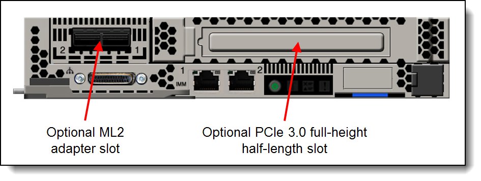
Figure 10. Optional front accessible PCIe slots
With the addition of the NeXtScale PCIe Native Expansion Tray, the server has two additional PCIe 3.0 x16 full-height full-length double-width slots, as described in the NeXtScale PCIe Native Expansion Tray section.
The ordering information for optional risers for the three slots is listed in the following table.
Table 47. Riser card options
| Part number | Feature code | Description | Maximum supported |
| 00FL180 | A5JV | nx360 M5 ML2 Riser | 1 |
| 00FL464 | A5JY | nx360 M5 Compute Node Front Riser | 1 |
| 00FL179 | A5JZ | nx360 M5 RAID Riser | 1 |
Network adapters
The nx360 M5 offers two Gigabit Ethernet ports with the following features:
- Broadcom BCM5717 Gigabit Ethernet controller
- TCP/IP Offload Engine (TOE) support
- Wake on LAN support
- Receive side Scaling (RSS) and Transmit side Scaling (TSS) support
- MSI and MSI-X capability (up to five MSI-X vectors)
- VLAN tag support (IEEE 802.1Q)
- Layer 2 priority encoding (IEEE 802.1p)
- Link aggregation (IEEE 802.3ad)
- Full-duplex flow control (IEEE 802.3x)
- IP, TCP, and UDP checksum offload (hardware based) on Tx/Rx over IPv4/IPv6
- Hardware TCP segmentation offload over IPv4/IPv6
- Jumbo frame support
- NIC Teaming (Load Balancing and Failover)
- One port that is shared with IMM2 by using the Network Controller-Sideband Interface (NC-SI)
The nx360 M5 server supports a Mezzanine LOM Generation 2 (ML2) adapter with a dedicated slot at the front of the server, as shown in the previous figure. The usage of an ML2 adapter also requires the installation of the ML2 Riser card. The Riser card and supported adapters are listed in the following table.
| Part number | Feature code | Description |
| Riser card for ML2 adapters | ||
| 00FL180 | A5JV | nx360 M5 ML2 Riser |
| ML2 Ethernet adapters | ||
| 00D2026 | A40S | Broadcom NetXtreme II ML2 Dual Port 10GbaseT for System x |
| 00D2028 | A40T | Broadcom NetXtreme II ML2 Dual Port 10GbE SFP+ for System x* |
| 01CV770 | AU7Z | Emulex VFA5.2 ML2 2x10 GbE SFP+ Adapter and FCoE/iSCSI SW* |
| 00AG560 | AT7U | Emulex VFA5.2 ML2 Dual Port 10GbE SFP+ Adapter* |
| 00JY940 | ATRH | Intel X710-DA2 ML2 2x10GbE SFP+ Adapter* |
| 00FP650 | A5RK | Mellanox ConnectX-3 Pro ML2 2x40GbE/FDR VPI Adapter for System x* |
| 00MN990 | ATZR | Mellanox ConnectX-4 Lx ML2 1x25GbE SFP28 Adapter |
| ML2 InfiniBand adapters | ||
| 00FP650 | A5RK | Mellanox ConnectX-3 Pro ML2 2x40GbE/FDR VPI Adapter for System x* |
* These adapters require either transceivers or direct-attach copper (DAC) cables. See the tables below.
The following table lists additional supported network adapters in the standard full-height half-length PCIe slot. The usage of an adapter in this slot also requires the installation of the PCIe Riser card.
| Part number | Feature code | Description |
| Riser card for PCIe adapters | ||
| 00FL464 | A5JY | nx360 M5 Compute Node Front Riser |
| 40 Gb Ethernet | ||
| 00D9550 | A3PN | Mellanox ConnectX-3 40GbE / FDR IB VPI Adapter for System x* |
| 00MM950 | ATRN | Mellanox ConnectX-4 Lx 1x40GbE QSFP28 Adapter* |
| 25 Gb Ethernet | ||
| 01GR250 | AUAJ | Mellanox ConnectX-4 Lx 2x25GbE SFP28 Adapter* |
| 10 Gb Ethernet | ||
| 44T1370 | A5GZ | Broadcom NetXtreme 2x10GbE BaseT Adapter for System x |
| 00AG570 | AT7S | Emulex VFA5.2 2x10 GbE SFP+ PCIe Adapter* |
| 00AG580 | AT7T | Emulex VFA5.2 2x10 GbE SFP+ Adapter and FCoE/iSCSI SW* |
| 49Y7960 | A2EC | Intel X520 Dual Port 10GbE SFP+ Adapter* |
| 49Y7970 | A2ED | Intel X540-T2 Dual Port 10GBaseT Adapter |
| 00MM850 | ATRY | Intel X550-T1 Single Port 10GBase-T Adapter |
| 00MM860 | ATPX | Intel X550-T2 Dual Port 10GBase-T Adapter |
| 01DA900 | AU2Y | Intel X710-DA2 2x10GbE SFP+ Adapter* |
| 00D9690 | A3PM | Mellanox ConnectX-3 10 GbE Adapter* |
| Gigabit Ethernet | ||
| 94Y5180 | A4Z6 | Broadcom NetXtreme Dual Port 10GbE SFP+ Adapter* |
| 90Y9370 | A2V4 | Broadcom NetXtreme I Dual Port GbE Adapter* |
| 90Y9352 | A2V3 | Broadcom NetXtreme I Quad Port GbE Adapter* |
| 00AG500 | A56K | Intel I350-F1 1xGbE Fiber Adapter* |
| 00AG510 | A56L | Intel I350-T2 2xGbE BaseT Adapter |
| 00AG520 | A56M | Intel I350-T4 4xGbE BaseT Adapter |
| InfiniBand | ||
| 00D9550 | A3PN | Mellanox ConnectX-3 40GbE / FDR IB VPI Adapter* |
| 00MM960 | ATRP | Mellanox ConnectX-4 2x100GbE/EDR IB QSFP28 VPI Adapter* |
| 00KH924 | ASWQ | Mellanox ConnectX-4 EDR IB VPI Single-port x16 PCIe 3.0 HCA* |
| Omni-Path Architecture (OPA) | ||
| 00WE023 | AU0A | Intel OPA 100 Series Single-port PCIe 3.0 x8 HFA |
| 00WE027 | AU0B | Intel OPA 100 Series Single-port PCIe 3.0 x16 HFA |
* These adapters require either transceivers or direct-attach copper (DAC) cables. See the tables below.
For more information, see the list of Product Guides in the Network adapters category:
https://lenovopress.com/servers/options/ethernet
The following table lists the supported 10 Gb Ethernet SFP+ optical transceivers and DAC cables. For multi-port adapters, all adapter ports must have the same type of transceiver or DAC cable selected.
| Part number | Feature code | Description |
|---|---|---|
| 10 GbE SFP+ LR transceivers (for SFP+ adapters) | ||
| 00FE331 | B0RJ | Lenovo 10GBASE-LR SFP+ Transceiver |
| 90Y9412 | A1PM | Lenovo 10Gb/s LR SFP+ XCVR |
| 10 GbE SFP+ SR transceivers (for SFP+ adapters) | ||
| 46C3447 | 5053 | Lenovo 10GBASE-SR SFP+ Transceiver |
| 49Y4216 | 0069 | Brocade 10Gb SFP+ SR Optical Transceiver |
| 49Y4218 | 0064 | QLogic 10Gb SFP+ SR Optical Transceiver |
| 10 GbE SFP+ DAC cables (for SFP+ adapters) | ||
| 00D6288 | A3RG | Lenovo 0.5m Passive SFP+ DAC Cable |
| 90Y9427 | A1PH | Lenovo 1m Passive SFP+ DAC Cable |
| 00AY764 | A51N | Lenovo 1.5m Passive SFP+ DAC Cable |
| 00AY765 | A51P | Lenovo 2m Passive SFP+ DAC Cable |
| 90Y9430 | A1PJ | Lenovo 3m Passive SFP+ DAC Cable |
| 90Y9433 | A1PK | Lenovo 5m Passive SFP+ DAC Cable |
| 00D6151 | A3RH | Lenovo 7m Passive SFP+ DAC Cable |
The following table lists the optical transceivers and DAC cables that can be used with the supported 40Gb Ethernet adapters listed. For multi-port adapters, all adapter ports must have the same type of transceiver or DAC cable selected.
| Part number | Feature code | Description |
|---|---|---|
| 40 GbE QSFP+ transceivers (for 40 GbE QSFP+ adapters) | ||
| 49Y7884 | A1DR | Lenovo 40GBASE-SR4 QSFP+ Transceiver |
| 40 GbE QSFP+ DAC cables (for 40 GbE QSFP+ adapters) | ||
| 49Y7890 | A1DP | Lenovo 1m Passive QSFP+ DAC Cable |
| 49Y7891 | A1DQ | Lenovo 3m Passive QSFP+ DAC Cable |
Fibre Channel host bus adapters
The following table lists the storage HBAs that are supported by the nx360 M5 server. These are installed in the full-height PCIe slot and require the riser also to be installed.
Table 52. Storage adapters
| Part number | Feature code | Description |
| Riser card for PCIe adapters | ||
| 00FL464 | A5JY | nx360 M5 Compute Node Front Riser |
| Fibre Channel - 16 Gb | ||
| 01CV830 | ATZU | Emulex 16Gb Gen6 FC Single-port HBA |
| 01CV840 | ATZV | Emulex 16Gb Gen6 FC Dual-port HBA |
| 01CV750 | ATZB | QLogic 16Gb Enhanced Gen5 FC Single-port HBA |
| 01CV760 | ATZC | QLogic 16Gb Enhanced Gen5 FC Dual-port HBA |
| 81Y1655 | A2W5 | Emulex 16Gb FC Single-port HBA for System x |
| 81Y1662 | A2W6 | Emulex 16Gb FC Dual-port HBA for System x |
| 00Y3337 | A3KW | QLogic 16Gb FC Single-port HBA for System x |
| 00Y3341 | A3KX | QLogic 16Gb FC Dual-port HBA for System x |
| Fibre Channel - 8 Gb | ||
| 42D0485 | 3580 | Emulex 8Gb FC Single-port HBA for System x |
| 42D0494 | 3581 | Emulex 8Gb FC Dual-port HBA for System x |
| 42D0501 | 3578 | QLogic 8Gb FC Single-port HBA for System x |
| 42D0510 | 3579 | QLogic 8Gb FC Dual-port HBA for System x |
For more information, see the list of Product Guides in the Host Bus Adapters category:
https://lenovopress.com/servers/options/hba
PCIe SSD adapters
The server supports the Flash Adapter adapters listed in the following table.
| Part number | Feature code | Description | Maximum supported |
|---|---|---|---|
| 00JY004 | ARYS* | 5200GB Enterprise io3 Flash Adapter | 1* |
* The io3 Flash Adapters cannot be factory installed; they are supported as field-installable options only. The server cannot be shipped with these adapters installed.
NeXtScale PCIe Native Expansion Tray
The NeXtScale PCIe Native Expansion Tray is a half-wide 1U expansion tray that attaches to the nx360 M5 to provide two full-height full-length double-width PCIe 3.0 x16 slots. The tray is designed to support two GPU adapters or coprocessors.
The use of the PCIe Native Expansion Tray requires that two processors be installed.
Note: All expansion trays are mutually exclusive. You can only attach one expansion tray to an nx360 M5 server.
The following figure shows the PCIe Native Expansion Tray attached to an nx360 M5 (shown with the top cover removed). The figure shows two NVIDIA GPUs installed.
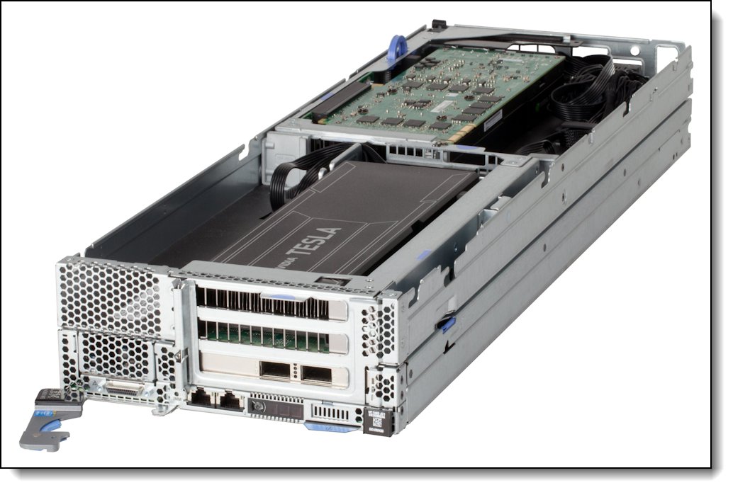
Figure 11. NeXtScale PCIe Native Expansion Tray attached to an nx360 M5 compute node
Ordering information is listed in the following table.
Table 54. Ordering information
| Part number | Feature code | Description |
| 00Y8393 | A4MB | NeXtScale PCIe Native Expansion Tray |
When the PCIe Native Expansion Tray is used, it is connected to the compute node through two riser cards, each providing a PCIe 3.0 x16 connector to the GPUs or coprocessors that are installed in the tray.
- A 2-slot PCIe 3.0 x24 riser card is installed in the front riser slot (riser slot 1; see Figure 3). This riser card replaces the standard 1-slot riser that is used to connect standard PCIe cards that are internal to the compute node. The 2-slot riser card offers these connections:
- PCIe 3.0 x8 slot for the slot internal to the compute node
- PCIe 3.0 x16 slots for the front adapter in the PCIe Native Expansion Tray
- A 1-slot PCIe 3.0 x16 riser card is installed in the rear riser slot (riser slot 2; see Figure 3). This riser is used to connect the rear adapter in the PCIe Native Expansion Tray.
Only GPUs and coprocessors are supported in the PCIe Native Expansion Tray and only those that are listed in the following section. The PCIe Native Expansion Tray also includes the auxiliary power connectors and cables for each adapter slot that is necessary for each supported GPU and coprocessor.
NeXtScale PCIe 2U Native Expansion Tray
The NeXtScale PCIe 2U Native Expansion Tray is a half-wide 2U expansion tray that attaches to the nx360 M5 to provide four full-height full-length double-width PCIe 3.0 x16 slots, 2 at the front and two at the rear of the tray. The tray is designed to support four GPUs or coprocessors, each up to 300 W. In addition, the expansion tray supports up to four 2.5-inch hot-swap SAS/SATA drives with the addition of a hot-swap backplane.
The following figure shows the PCIe 2U Native Expansion Tray.
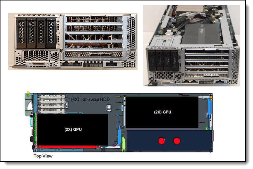
Figure 12. PCIe 2U Native Expansion Tray connected to an nx360 M5 server
Ordering information is listed in the following table.
Table 55. Ordering information
| Part number | Feature code | Description |
| 00MU758 | ASYK | NeXtScale PCIe 2U Native Expansion Tray |
| 44X4104 | A4A6 | 4x 2.5" HDD Riser (Backplane and SAS cable) |
When the PCIe 2U Native Expansion Tray is used, it is connected to the compute node through two riser cards:
- The front riser card connects to processor 1 via the PCIe 3.0 x24 slot at the front of the server and provides three slots:
- One PCIe 3.0 x8 for the full-height half-length slot internal to the nx360 M5 server
- Two PCIe 3.0 x16 full-height full-length double-width slots for GPUs or coprocessors
- The rear riser card connects to processor 2 via the PCIe 3.0 x16 slot at the front of the server and provides two slots:
- Two PCIe 3.0 x16 full-height full-length double-width slots for GPUs or coprocessors
Each riser contains a PEX 8764 PCIe 3.0 switch that enables both x16 slots in the riser to operate at full x16 width. The two riser cards are also connected to each other via two PCIe cables connected to the PCIe switch chips on each riser. The bridge cables allow all four x16 slots to usable even with only 1 processor installed. The connections and slots are shown in the following figure.
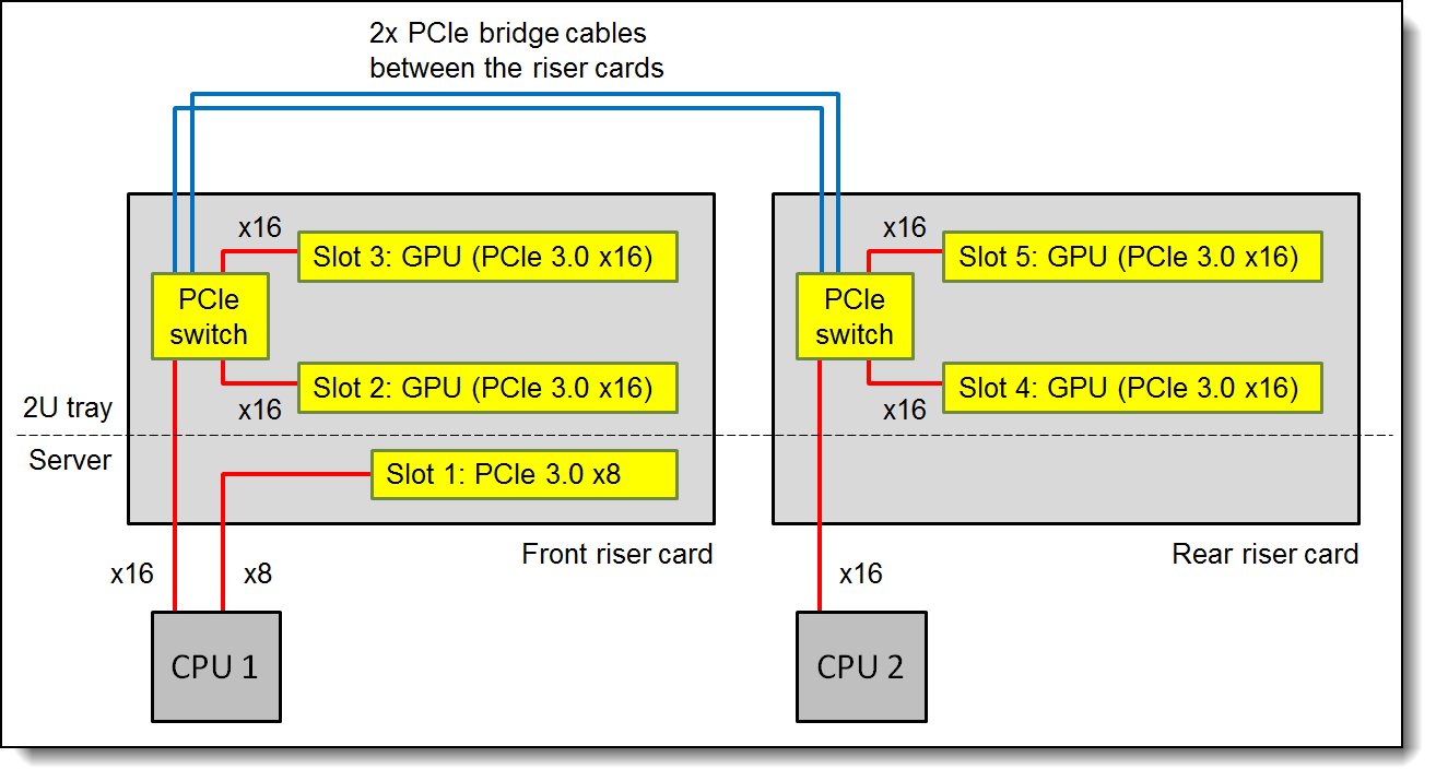
Figure 13. Block diagram of the PCIe 2U Native Expansion Tray
Only GPUs and coprocessors are supported in the PCIe 2U Native Expansion Tray and only those that are listed in the following section. The PCIe 2U Native Expansion Tray also includes the auxiliary power connectors and cables for each adapter slot that is necessary for each supported GPU and coprocessor.
GPU and coprocessor adapters
The nx360 M5 supports GPU adapters and coprocessors when the NeXtScale PCIe Native Expansion Tray or PCIe 2U Native Expansion Tray is attached. The following table lists the supported adapters.
The operating systems that are supported by each GPU and coprocessor adapter is listed in the Supported operating systems section.
When the PCIe Native Expansion Tray is used, the configuration rules are as follows:
- Two processors must be installed in the compute node.
- One or two GPUs or coprocessors can be installed.
- If two GPU adapters or coprocessors are installed, they must be identical.
- 1300 W power supplies are required in the chassis.
- 200 - 240 V AC utility power is required. 100 - 127 V AC is not supported.
When the PCIe 2U Native Expansion Tray is used, the configuration rules are as follows:
- When 1 processor and 3 or 4 GPUs are installed, the PCIe bridge cable must also be installed
- When 2 processors and 3 or 4 GPUs are installed, the PCIe bridge cable must be removed
- All GPU adapters or coprocessors installed in the tray must be identical.
- 1300 W power supplies are required in the chassis.
- 200 - 240 V AC utility power is required. 100 - 127 V AC is not supported.
Note: Larger numbers of GPUs may be supported via Special Bid than listed in this table, for example up to four NVIDIA K80 or four Intel Xeon Phi 7120P can be supported in the 2U Tray with additional considerations.
| Part number |
Feature code |
Description | Power consumption |
Maximum supported*
|
|
|---|---|---|---|---|---|
| 1U Tray (2 CPUs) |
2U Tray (1 CPU / 2 CPUs) |
||||
| 00KG655 | ATZE | NVidia Tesla M60 GPU, PCIe (passive) | 300 W | 2 | 2 / 2 |
| 7C57A02891 | AX8L | NVIDIA Tesla M10 GPU, PCIe (passive) | 225 W | 2 | 2 / 2 |
| 7C57A02888 | AVNZ | NVIDIA Tesla P40 GPU, PCIe (passive) | 250 W | 2 | 2 / 2 |
| 7X67A00068 | AUV5 | NVIDIA Tesla P100 16GB GPU PCIe (Passive) | 250 W | 2 | 2 / 2 |
* Maximums with PCIe Native Expansion Tray (1U Tray) / PCIe 2U Native Expansion Tray (2U Tray)
Power supplies
The NeXtScale n1200 enclosure supports up to six redundant hot-plug power supplies, providing N+N or N+1 redundancy. Power policies with no redundancy also are supported. These High Efficiency (HE) Platinum AC power supplies are 80 PLUS Platinum certified to allow for the best efficiency values of your data center. The following table lists the supported power supply options.
| Part number | Feature code | Description | FPC support† | Min / Max supported |
Chassis model where used |
|---|---|---|---|---|---|
| 00Y8569 | A41T | CFF 900W Power Supply (Platinum) | Both | 6 / 6 | A2x, B2x |
| 00Y8652 | A4MM | NeXtScale n1200 CFF 1300W Power Supply (Platinum) | Both | 2 / 6 | A3x, A4x, B3x, B4x |
| 00MU774 | ASYH | NeXtScale n1200 1300W Titanium Power Supply | Lenovo | 2 / 6 | - |
| 00MU775 | ASYJ | NeXtScale n1200 1500W Platinum Power Supply | Lenovo | 2 / 6 | - |
| 00KG685* | ASGJ | CFF -48V DC 900W Power Supply | Lenovo | 6 / 6 | - |
* Withdrawn from marketing
† Fan & Power Controllers are either IBM-signed firmware (standard in Axx chassis models) or Lenovo-signed firmware (standard in Bxx models, or available as 00MU639)
The power supply options have the following features:
- Supports N+N or N+1 Power Redundancy, or Non-redundant power configurations to support higher density
- Power management controller and configured through the Fan and Power Controller
- Integrated 2500 RPM fan
- 80 PLUS Platinum or Titanium certified
- Built-in overload and surge protection
1500 W AC power supply specifications:
- Supports high-range voltage only: 200 - 240 V
- 200 - 240 (nominal) V AC; 50 or 60 Hz; 8.2 A (maximum)
1300 W AC power supply specifications:
- Supports high-range voltage only: 200 - 240 V
- 200 - 240 (nominal) V AC; 50 or 60 Hz; 6.9 A (maximum)
900 W AC power supply specifications:
- Supports dual-range voltage: 100 - 240 V
- 100 - 127 (nominal) V AC; 50 or 60 Hz; 6.8 A (maximum)
- 200 - 240 (nominal) V AC; 50 or 60 Hz; 5.0 A (maximum)
-48V DC 900 W power supply specifications:
- Supports -40 V to -75 V dc (-48 V nominal)
- Maximum input current 25.8A
- 3-cable (-48V, RTN, and GND) terminal block
- Line cord not included
Integrated virtualization
The server supports VMware vSphere (ESXi), which is installed on a USB memory key. The key is installed in a USB socket inside the server. The following table lists the virtualization options.
Customized VMware vSphere images can be downloaded from the following website:
https://vmware.lenovo.com/content/custom_iso/
Table 58. Virtualization options - USB Memory Keys
| Part number | Feature code |
Description | Maximum supported |
| 00WH140 | ATRM | Blank USB Memory Key 4G SLC for VMware ESXi Downloads | 1 |
| 41Y8298 | A2G0 | Blank USB Memory Key for VMware ESXi Downloads | 1 |
| 00ML233 | ASN6 | USB Memory Key for VMware ESXi 5.1 Update 2 | 1 |
| 00ML235 | ASN7 | USB Memory Key for VMware ESXi 5.5 Update 2 | 1 |
| 00WH138 | ATRL | USB Memory Key 4G for VMware ESXi 6.0 Update 1A | 1 |
| 00WH150 | ATZG | USB Memory Key for VMware ESXi 5.5 Update 3B | 1 |
| 00WH151 | ATZH | USB Memory Key for VMware ESXi 6.0 Update 2 | 1 |
| CTO only | AVNW | USB Memory Key for VMware ESXi 6.5 | 1 |
The nx360 M5 also supports the VMware vSphere (ESXi) hypervisor on one or two SD cards with the optional SD Media Adapter for System x. This adapter is installed in a dedicated slot as shown in Figure 3.
When only one SD card is installed in the adapter, you can create up to 16 volumes, each of which is presented to UEFI as a bootable device. When two SD Media cards are inserted, volumes can be mirrored (RAID 1) across both cards, up to a total of eight mirrored volumes. The use of mirrored volumes improves system availability because the server remains operational, even if one SD card fails. The RAID functionality is handled internally by the SD Media Adapter.
The following table shows the available options. The table also indicates how many SD cards are included.
Table 59. Virtualization options - SD Cards
| Part number | Feature code |
Description | SD Cards included |
| 00ML706 | A5TJ | SD Media Adapter for Systems x (Option 00ML706 includes 2 blank 32GB SD cards) |
2* |
| 00ML700 | AS2V | Blank 32GB SD Media for System x | 1 |
| None | ATS9 | RAID Adapter for SD Media w/VMware ESXi 6.0 U1A (2 SD Media, RAIDed) | 2 |
| None | ATSA | RAID Adapter for SD Media w/ VMware ESXi 6.0 U1A (1 SD Media) | 1 |
| None | AVNX | Adapter for SD Media w/ VMware ESXi 6.5 (1 SD Media) | 1 |
| None | AVNY | Adapter for SD Media w/ VMware ESXi 6.5 (2 SD Media, RAIDed) | 2 |
* Option 00ML706 includes two 32GB SD cards; however, for CTO orders, feature code A5TJ does not include SD media and the SD Cards must be selected separately.
Customized VMware vSphere images can be downloaded from the following website:
https://vmware.lenovo.com/content/custom_iso/
Local server management
The nx360 M5 provides local console access through the KVM connector at the front of the server. A console breakout cable is used with this connector, which provides a VGA port, two USB ports, and a DB9 serial port. The cable is shown in the following figure.
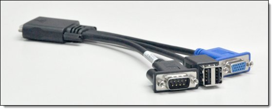
Figure 14. Console breakout cable
One console breakout cable is shipped with the NeXtScale n1200 enclosure. Additional cables can be ordered per the following table.
Table 60. Console breakout cable
| Part number | Feature code |
Description | Maximum supported |
| 00Y8366 | A4AK | Console breakout cable (KVM Dongle cable) | 1 |
Tip: This is the same cable that is used with Flex System, but has a different part number because of the included materials.
To aid with problem determination, the server includes light path diagnostics, which is a set of LEDs on the front of the server and inside the server that show you which component is failing. The LEDs are shown in the following figure.
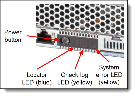
Figure 15. Power button and system LEDs
When an error occurs, the system error LED lights up. Review the logs through the web interface of the IMMv2 (see the "Remote server management" section). If needed, Then, press and hold the light path diagnostics button on the system board (see location on Figure 3) to activate the system board LEDs. The LED next to the failed component lights up.
Remote server management
Lenovo XClarity Administrator is centralized resource management solution that is aimed at reducing complexity, speeding response, and enhancing the availability of Lenovo® server systems and solutions.
Lenovo XClarity Administrator provides agent-free hardware management for ThinkServer, System x and Flex System servers. The administration dashboard, shown in the following figure, is based on HTML 5 allows fast location of resources so tasks can be run quickly.
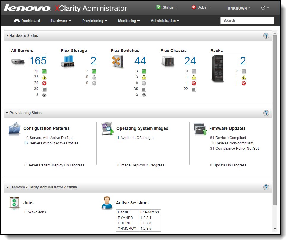
Figure 16. Lenovo XClarity Administrator dashboard
Because Lenovo XClarity Administrator does not include any agent software that is installed on the managed endpoints, there are no CPU cycles spent on agent execution and no memory is used, which means that up to 1GB of RAM and 1 - 2% CPU usage is saved, compared to a typical managed system where an agent is required.
Lenovo XClarity Administrator supports the following functions with the nx360 M5 server:
- Discovery
- Inventory
- Monitoring & alerting
- Call home
- Centralized user management
- Cryptography modes, server certificates, and encapsulation
- Configuration patterns
- Operating system deployment
- Firmware updates
Note that the following restrictions apply with XClarity Administrator and the nx360 M5:
- For servers running ESXi, ESXi 5.1 U3 or later is required to support OS deployment.
- Power and thermal metrics are not supported
- This server is not supported in the rack view
For more information about Lenovo XClarity Administrator, including ordering part numbers, see the Lenovo XClarity Administrator Product Guide:
https://lenovopress.com/tips1200-lenovo-xclarity-administrator
Each NeXtScale nx360 M5 compute node has an Integrated Management Module II (IMM 2.1) onboard and uses the Unified Extensible Firmware Interface (UEFI).
The IMM provides advanced service-processor control, monitoring, and an alerting function. If an environmental condition exceeds a threshold or if a system component fails, the IMM lights LEDs to help you diagnose the problem, records the error in the event log, and alerts you about the problem. Optionally, the IMM also provides a virtual presence capability for remote server management capabilities. The IMM provides remote server management through the following industry-standard interfaces:
- Intelligent Platform Management Interface (IPMI) version 2.0
- Simple Network Management Protocol (SNMP) version 3.0
- Common Information Model (CIM)
- Web browser
The IMM2.1 also provides the following remote server management capabilities through the ipmitool management utility program:
- Command-line interface (IPMI Shell)
The command-line interface provides direct access to server management functions through the IPMI 2.0 protocol. Use the command-line interface to issue commands to control the server power, view system information, and identify the server. You can also save one or more commands as a text file and run the file as a script.
- Serial over LAN
Establish a Serial over LAN (SOL) connection to manage servers from a remote location. You can remotely view and change the UEFI settings, restart the server, identify the server, and perform other management functions. Any standard Telnet client application can access the SOL connection.
The NeXtScale nx360 M5 server includes IMM Basic and can be upgraded to IMM Standard and IMM Advanced with Feature on Demand (FoD) licenses.
IMM2 Basic has the following features:
- Industry-standard interfaces and protocols
- Intelligent Platform Management Interface (IPMI) Version 2.0
- Common Information Model (CIM)
- Advanced Predictive Failure Analysis (PFA) support
- Continuous health monitoring
- Shared Ethernet connection
- Domain Name System (DNS) server support
- Dynamic Host Configuration Protocol (DHCP) support
- Embedded Dynamic System Analysis (DSA)
- LAN over USB for in-band communications to the IMM
- Serial over LAN
- Remote power control
- Server console serial redirection
IMM2 Standard (as enabled by using the Feature on Demand software license key using part number 90Y3900) has the following features in addition to the IMM2 Basic features:
- Remote access through a secure web console
- Access to server vital product data (VPD)
- Automatic notification and alerts
- Continuous health monitoring and control
- Email alerts
- Syslog logging support
- Enhanced user authority levels
- Event logs that are time stamped, saved on the IMM, and that can be attached to email alerts
- OS watchdogs
- Remote configuration through Advanced Settings Utility (ASU)
- Remote firmware updating
- User authentication using a secure connection to a Lightweight Directory Access Protocol (LDAP) server
IMM2 Advanced (as enabled by using the Feature on Demand software license key using part number 90Y3901) adds the following features on top of those of IMM Standard:
- Remotely viewing video with graphics resolutions up to 1600x1200 at 75 Hz with up to 23 bits per pixel color depths, regardless of the system state
- Remotely accessing the server by using the keyboard and mouse from a remote client
- Mapping the CD or DVD drive, diskette drive, and USB flash drive on a remote client, and mapping ISO and diskette image files as virtual drives that are available for use by the server
- Uploading a diskette image to the IMM memory and mapping it to the server as a virtual drive
The blue-screen capture feature captures the video display contents before the IMM restarts the server when the IMM detects an operating system hang condition. A system administrator can use the blue-screen capture to assist in determining the cause of the hang condition.
The following table lists the remote management options.
Note: The IMM2 Advanced upgrade requires the IMM2 Standard upgrade.
Table 61. Remote management options
| Part number | Feature codes |
Description | Maximum supported |
| 90Y3900 | A1MK | Integrated Management Module Standard Upgrade | 1 |
| 90Y3901 | A1ML | Integrated Management Module Advanced Upgrade (requires Standard Upgrade, 90Y3900) |
1 |
The nx360 M5 provides two 1 Gb Ethernet ports standard, one of which (port 1) is configured in UEFI by default to be shared between the operating system and the IMM2.
In shared mode, this port enables you to connect remotely to the IMM2 to perform systems management functions and provides a 10/100 Mbps Ethernet connection to the IMM2. A third Ethernet port is optional (with the addition of the IMM management Interposer) and provides a dedicated 1 Gbps Ethernet connection to the IMM2.
When the IMM management interposer is in use, port 1 of the two standard Ethernet ports no longer provides access to the IMM but is instead dedicated to the operating system.

Figure 17. IMM ports
The following table lists the ordering information for the dedicated IMM2 port option.
Table 62. Dedicated IMM2 Ethernet port option
| Part number | Feature codes |
Description | Maximum supported |
| 00FL177 | A5JX | nx360 M5 IMM Management Interposer | 1 |
Remote enclosure management
The NeXtScale n1200 Enclosure offers a remote management capability through the Fan and Power Controller, which is at the back of the enclosure, as shown in the following figure.
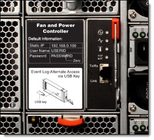
Figure 18. Fan and Power Controller
The Fan and Power Controller has one external RJ45 port, which provides a 10/100 Mbps Ethernet connection for browser-based remote control.
The port provides the following interfaces:
- An HTTP (web browser) interface for remote management of the FPC
- An IPMI interface for remote management of the FPC
- An IPMI interface to higher managers, such as xCAT
The module provides the following functions:
- Power supply redundancy and over-subscription configuration
- Power capping/saving configuration
- Power restore policy
- Acoustic mode setting
- Configuration/log export to USB (a USB port is provided inside the module)
- IMM remote reset or Server remote reseat (AC cycle)
- Status monitor: Power consumption, node status, power supply status, and fan status
- Network configuration
The FPC also includes a USB key that is housed inside the unit. The USB key stores the event log for the FPC plus power, cooling, and network configuration data.
There are two Fan and Power Controller components available as listed in the following table. The only difference between the two FPC components is the firmware codebase. Feature code A41G has IBM-signed firmware and feature code ASUM has Lenovo-signed firmware.
Table 63. Fan and Power Controller
| Part number |
Feature codes |
Description | Firmware codebase |
Chassis models where used |
| None | A41G | n1200 Enclosure Fan Power Control Card Assembly | IBM-signed | A2x, A3x, A4x |
| 00MU639 | ASUM | Lenovo n1200 Enclosure Fan and Power Controller 2 | Lenovo-signed | B2x, B3x, B4x |
Rack installation
The NeXtScale n1200 enclosure includes a rail kit and lift handles. These items are shown in the following figure.
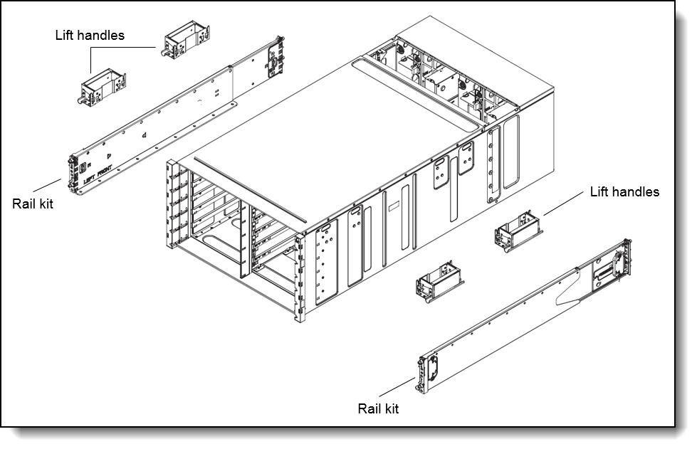
Figure 19. Rail kit and lift handles
Operating system support
The server supports the following operating systems:
- Microsoft Windows Server 2012
- Microsoft Windows Server 2012 R2
- Microsoft Windows Server 2016
- Microsoft Windows Server, version 1709
- Red Hat Enterprise Linux 6.10 x64
- Red Hat Enterprise Linux 6.7 x64
- Red Hat Enterprise Linux 6.8 x64
- Red Hat Enterprise Linux 7.2
- Red Hat Enterprise Linux 7.3
- Red Hat Enterprise Linux 7.4
- Red Hat Enterprise Linux 7.5
- Red Hat Enterprise Linux 7.6
- Red Hat Enterprise Linux 7.7
- Red Hat Enterprise Linux 7.8
- Red Hat Enterprise Linux 7.9
- SUSE Linux Enterprise Server 11 Xen x64 SP4
- SUSE Linux Enterprise Server 11 x64 SP4
- SUSE Linux Enterprise Server 12 SP1
- SUSE Linux Enterprise Server 12 SP2
- SUSE Linux Enterprise Server 12 SP3
- SUSE Linux Enterprise Server 12 SP4
- SUSE Linux Enterprise Server 12 SP5
- SUSE Linux Enterprise Server 12 Xen SP1
- SUSE Linux Enterprise Server 12 Xen SP2
- SUSE Linux Enterprise Server 12 Xen SP3
- SUSE Linux Enterprise Server 12 Xen SP4
- SUSE Linux Enterprise Server 12 Xen SP5
- SUSE Linux Enterprise Server 15
- SUSE Linux Enterprise Server 15 SP1
- SUSE Linux Enterprise Server 15 SP2
- SUSE Linux Enterprise Server 15 SP3
- SUSE Linux Enterprise Server 15 SP4
- SUSE Linux Enterprise Server 15 Xen
- SUSE Linux Enterprise Server 15 Xen SP1
- SUSE Linux Enterprise Server 15 Xen SP2
- SUSE Linux Enterprise Server 15 Xen SP3
- SUSE Linux Enterprise Server 15 Xen SP4
- VMware ESXi 5.5 U3
- VMware ESXi 6.0 U2
- VMware ESXi 6.0 U3
- VMware ESXi 6.5
- VMware ESXi 6.5 U1
- VMware ESXi 6.5 U2
- VMware ESXi 6.5 U3
- VMware ESXi 6.7
- VMware ESXi 6.7 U1
- VMware ESXi 6.7 U2
- VMware ESXi 6.7 U3
For a complete list of supported, certified and tested operating systems, plus additional details and links to relevant web sites, see the Operating System Interoperability Guide: https://lenovopress.com/osig#servers=nx360-m5-5465-e5-v4
The following table lists the operating system support for GPUs and coprocessors.
|
Intel Xeon Phi 5110P
|
Intel Xeon Phi 7120P
|
NVIDIA GRID K1
|
NVIDIA GRID K2
|
NVIDIA Tesla K40
|
NVIDIA Tesla K80
|
NVidia Tesla M40
|
NVidia Tesla M60
|
|
|---|---|---|---|---|---|---|---|---|
| Microsoft Windows Server 2012 R2 | Y | Y | Y | Y | Y | Y | Y | Y |
| Microsoft Windows Server 2012 | Y | Y | Y | Y | Y | Y | Y | Y |
| Red Hat Enterprise Linux 7 | Y | Y | N | N | Y | Y | Y | Y |
| Red Hat Enterprise Linux 6 x64 | Y | Y | N | N | Y | Y | Y | Y |
| SUSE Linux Enterprise Server 12 | Y | Y | N | N | Y | Y | Y | Y |
| SUSE Linux Enterprise Server 12 with Xen | Y | Y | N | N | Y | Y | Y | Y |
| SUSE Linux Enterprise Server 11 x64 | Y | Y | N | N | Y | Y | Y | Y |
| SUSE Linux Enterprise Server 11 x64 with Xen | Y | Y | N | N | Y | Y | Y | Y |
| VMware vSphere 6.0 (ESXi) | N | N | Y | Y | N | N | N | Y |
| VMware vSphere 5.5 (ESXi) | N | N | Y | Y | N | N | N | N |
Physical and electrical specifications
Here are the NeXtScale nx360 M5 dimensions:
- Width: 216 mm (8.5 in.)
- Height: 41 mm (1.6 in.)
- Depth: 659 mm (25.9 in.)
- Maximum weight: 6.17 kg (13.6 lb)
Here are the NeXtScale n1200 enclosure dimensions:
- Width: 447 mm (17.6 in.)
- Height: 263 mm (10.4 in.)
- Depth: 915 mm (36 in.)
- Fully configured (stand-alone): 112 kg (247 lb), empty chassis 28 kg (62 lb)
Supported environment
The NeXtScale nx360 M5 compute node complies with ASHRAE class A3 specifications. The supported environment when powered on is as follows:
- Temperature: 5°C - 40°C (41°F - 104°F) up to 950 m (3,117 ft)
- Above 950m, de-rated maximum air temperature 1C / 175m
- Humidity, non-condensing: -12°C dew point (10.4°F) and 8% - 85% relative humidity
- Maximum dew point: 24°C (75°F)
- Maximum altitude: 3050 m (10,000 ft) and 5°C - 28°C (41°F - 82°F)
The minimum humidity level for class A3 is the higher (more moisture) of the -12°C dew point and the 8% relative humidity. These intersect at approximately 25°C. Below this intersection (~25°C), the dew point (-12°C) represents the minimum moisture level, while above it relative humidity (8%) is the minimum.
Moisture levels lower than 0.5°C DP, but not lower -10 °C DP or 8% relative humidity, can be accepted if appropriate control measures are implemented to limit the generation of static electricity on personnel and equipment in the data center. All personnel and mobile furnishings and equipment must be connected to ground through an appropriate static control system. The following items are considered the minimum requirements:
- Conductive materials (conductive flooring, conductive footwear on all personnel that go into the data center, and all mobile furnishings and equipment will be made of conductive or static dissipative materials).
- During maintenance on any hardware, a properly functioning wrist strap must be used by any personnel who come into contact with IT equipment.
If you adhere to ASHRAE Class A3, Temperature: 36°C - 40°C (96.8°F - 104°F) with relaxed support:
- A support cloud like workload with no performance degradation is acceptable (Turbo-Off).
- Under no circumstance can any combination of worst case workload and configuration result in system shutdown or design exposure at 40°C.
- The worst case workload (like Linpack and Turbo-On) might have performance degradation.
Specific component restrictions:
- Intel Xeon Phi 7120P: Temperature: 5°C - 30°C (41°F - 86°F); Altitude: 0 – 304.8 m (1000ft).
- nx360 M5 with rear HDD: Temperature: 5°C - 30°C (41°F - 86°F); Altitude: 0 – 304.8 m (1000ft).
Electrical requirements
- 100 - 127 (nominal) V AC; 50 Hz or 60 Hz; 6.8 A
- 200 - 240 (nominal) V AC; 50 Hz or 60 Hz; 5.0 A
- Input kilovolt-amperes (kVA) (approximately):
- Minimum configuration: 0.1 kVA
- Maximum configuration: 6.0 kVA
BTU output
- Minimum configuration: 341 Btu/hr (100 watts)
- Maximum configuration: 20,471 Btu/hr (6,000 watts)
Acoustic (noise) level
- 7.0 bels (idle)
Regulatory compliance
The server conforms to the following international standards:
- Energy Star 2.1
- FCC - Verified to comply with Part 15 of the FCC Rules, Class A
- Canada ICES-003, issue 5, Class A
- UL/IEC 60950-1
- CSA C22.2 No. 60950-1
- NOM-019
- Argentina IEC60950-1
- Japan VCCI, Class A
- IEC 60950-1 (CB Certificate and CB Test Report)
- China CCC GB4943.1, GB9254, Class A, and GB17625.1
- Taiwan BSMI CNS13438, Class A; CNS14336-1
- Australia/New Zealand AS/NZS CISPR 22, Class A; AS/NZS 60950.1
- Korea KN22, Class A, KN24
- Russia/GOST ME01, IEC-60950-1, GOST R 51318.22, and GOST R 51318.24,
- GOST R 51317.3.2, GOST R 51317.3.3
- IEC 60950-1 (CB Certificate and CB Test Report)
- CE Mark (EN55022 Class A, EN60950-1, EN55024, and EN61000-3-2,
- EN61000-3-3)
- CISPR 22, Class A
- TUV-GS (EN60950-1/IEC 60950-1, and EK1-ITB2000)
Warranty options
The system has a three-year customer-replaceable unit (CRU) and onsite (for field-replaceable units (FRUs) only) limited warranty with standard call center support during normal business hours and 9x5 Next Business Day Parts Delivered.
Also available are Lenovo Services warranty maintenance upgrades and post-warranty maintenance agreements, with a predefined scope of services, including service hours, response time, term of service, and service agreement terms and conditions.
Lenovo warranty service upgrade offerings are region-specific. Not all warranty service upgrades are available in every region. For more information about Lenovo warranty service upgrade offerings that are available in your region, go to the Data Center Advisor and Configurator website http://dcsc.lenovo.com, then do the following:
- In the Customize a Model box in the middle of the page, select the Services option in the Customization Option dropdown menu
- Enter the machine type & model of the system
- From the search results, you can click either Deployment Services or Support Services to view the offerings
The following table explains warranty service definitions in more detail.
| Term | Description |
|---|---|
| Onsite Service | If a problem with your product cannot be resolved via telephone, a Service Technician will be dispatched to arrive at your location. |
| Parts Delivered | If a problem with your product cannot be resolved via telephone and a CRU part is required, Lenovo will send a replacement CRU to arrive at your location. If a problem with your product cannot be resolved via telephone and a FRU part is required, a Service Technician will be dispatched to arrive at your location. |
| Technician Installed Parts | If a problem with your product cannot be resolved via telephone, a Service Technician will be dispatched to arrive at your location. |
| Hours of coverage |
|
| Response time target | 2 hours, 4 hours, or Next Business Day: The time period from when the telephone based troubleshooting is completed and logged, to the delivery of the CRU or arrival of a Service Technician and part at the Customer’s location for repair. |
| Committed Repair | 6 hours: The time period between the service request registration in Lenovo’s call management system and the restoration of the product to conformance with its specification by a Service Technician. |
The following Lenovo warranty service upgrades are available:
- Warranty and maintenance service upgrades:
- Three, four, or five years of 9x5 or 24x7 service coverage
- Parts delivered or technician installed parts from next business day to 4 or 2 hours
- Committed repair service
- Warranty extension of up to 5 years
- Post warranty extensions
- Committed Repair Service
Committed Repair Services enhances the level of Warranty Service Upgrade or Post Warranty/Maintenance Service offering associated with the selected systems. Offerings vary and are available in select countries.
- Priority handling to meet defined time frames to restore the failing machine to good working condition
- 24x7x6 committed repair: Service performed 24 hours per day, 7 days per week, within 6 hours
- YourDrive YourData
Lenovo’s YourDrive YourData service is a multi-drive retention offering that ensures your data is always under your control, regardless of the number of drives that are installed in your Lenovo server. In the unlikely event of a drive failure, you retain possession of your drive while Lenovo replaces the failed drive part. Your data stays safely on your premises, in your hands. The YourDrive YourData service can be purchased in convenient bundles with Lenovo warranty upgrades and extensions.
- Microcode Support
Keeping microcode current helps prevent hardware failures and security exposure. There are two levels of service: analysis of the installed base and analysis and update where required. Offerings vary by region and can be bundled with other warranty upgrades and extensions.
- Enterprise Software Support
Lenovo Enterprise Server Software Support can help you troubleshoot your entire server software stack. Choose support for server operating systems from Microsoft, Red Hat, SUSE, and VMware; Microsoft server applications; or both operating systems and applications. Support staff can help answer troubleshooting and diagnostic questions, address product compatibility and interoperability issues, isolate causes of problems, report defects to software vendors, and more.
In addition, you can access hardware “how to” support for System x servers. Staff can help resolve hardware problems not covered under warranty, refer you to the right documentation and publications, provide corrective service information for known defects, and transfer you to a hardware support call center if needed.
- Hardware Installation Services
Lenovo experts can seamlessly manage the physical installation of your server, storage, or networking hardware. Working at a time convenient for you (business hours or off shift), the technician will unpack and inspect the systems on your site, install options, mount in a rack cabinet, connect to power and network, check and update firmware to the latest levels, verify operation, and dispose of the packaging, allowing your team to focus on other priorities. Your new systems will be configured and ready for your software installation.
Rack cabinets
The NeXtScale n1200 enclosure is supported in the following racks:
- 42U 1100 mm Enterprise V2 Deep Dynamic Rack
- 42U 1100 mm Dynamic Enterprise V2 Expansion Rack
For more information about these racks, see the data sheet:
http://www.lenovo.com/images/products/system-x/pdfs/datasheets/42u_enterprise_v2_dynamic_rack.pdf
KVM console options
The following table lists the supported KVM consoles, keyboards, and KVM switches.
| Part number | Description |
| Consoles | |
| 17238BX | 1U 18.5" Standard Console (without keyboard) |
| Console keyboards | |
| 00MW310 | Lenovo UltraNav Keyboard USB - US Eng |
| 46W6713 | Keyboard w/ Int. Pointing Device USB - Arabic 253 RoHS v2 |
| 46W6714 | Keyboard w/ Int. Pointing Device USB - Belg/UK 120 RoHS v2 |
| 46W6715 | Keyboard w/ Int. Pointing Device USB - Chinese/US 467 RoHS v2 |
| 46W6716 | Keyboard w/ Int. Pointing Device USB - Czech 489 RoHS v2 |
| 46W6717 | Keyboard w/ Int. Pointing Device USB - Danish 159 RoHS v2 |
| 46W6718 | Keyboard w/ Int. Pointing Device USB - Dutch 143 RoHS v2 |
| 46W6719 | Keyboard w/ Int. Pointing Device USB - French 189 RoHS v2 |
| 46W6720 | Keyboard w/ Int. Pointing Device USB - Fr/Canada 445 RoHS v2 |
| 46W6721 | Keyboard w/ Int. Pointing Device USB - German 129 RoHS v2 |
| 46W6722 | Keyboard w/ Int. Pointing Device USB - Greek 219 RoHS v2 |
| 46W6723 | Keyboard w/ Int. Pointing Device USB - Hebrew 212 RoHS v2 |
| 46W6724 | Keyboard w/ Int. Pointing Device USB - Hungarian 208 RoHS v2 |
| 46W6725 | Keyboard w/ Int. Pointing Device USB - Italian 141 RoHS v2 |
| 46W6726 | Keyboard w/ Int. Pointing Device USB - Japanese 194 RoHS v2 |
| 46W6727 | Keyboard w/ Int. Pointing Device USB - Korean 413 RoHS v2 |
| 46W6728 | Keyboard w/ Int. Pointing Device USB - LA Span 171 RoHS v2 |
| 46W6729 | Keyboard w/ Int. Pointing Device USB - Norwegian 155 RoHS v2 |
| 46W6730 | Keyboard w/ Int. Pointing Device USB - Polish 214 RoHS v2 |
| 46W6731 | Keyboard w/ Int. Pointing Device USB - Portuguese 163 RoHS v2 |
| 46W6732 | Keyboard w/ Int. Pointing Device USB - Russian 441 RoHS v2 |
| 46W6733 | Keyboard w/ Int. Pointing Device USB - Slovak 245 RoHS v2 |
| 46W6734 | Keyboard w/ Int. Pointing Device USB - Spanish 172 RoHS v2 |
| 46W6735 | Keyboard w/ Int. Pointing Device USB - Swed/Finn 153 RoHS v2 |
| 46W6736 | Keyboard w/ Int. Pointing Device USB - Swiss F/G 150 RoHS v2 |
| 46W6737 | Keyboard w/ Int. Pointing Device USB - Thai 191 RoHS v2 |
| 46W6738 | Keyboard w/ Int. Pointing Device USB - Turkish 179 RoHS v2 |
| 46W6739 | Keyboard w/ Int. Pointing Device USB - UK Eng 166 RoHS v2 |
| 46W6740 | Keyboard w/ Int. Pointing Device USB - US Euro 103P RoHS v2 |
| 46W6741 | Keyboard w/ Int. Pointing Device USB - Slovenian 234 RoHS v2 |
| Console switches | |
| 1754D2X | Global 4x2x32 Console Manager (GCM32) |
| 1754D1X | Global 2x2x16 Console Manager (GCM16) |
| 1754A2X | Local 2x16 Console Manager (LCM16) |
| 1754A1X | Local 1x8 Console Manager (LCM8) |
| Console switch cables | |
| 43V6147 | Single Cable USB Conversion Option (UCO) |
| 39M2895 | USB Conversion Option (4 Pack UCO) |
| 46M5383 | Virtual Media Conversion Option Gen2 (VCO2) |
| 46M5382 | Serial Conversion Option (SCO) |
For more information, see the list of Product Guides in the KVM Switches and Consoles category:
http://lenovopress.com/servers/options/kvm
External disk storage systems
The following table lists the Fibre Channel external storage systems that are offered by Lenovo.
Table 67. External disk storage systems
| Part number | Description |
| Lenovo Storage S2200 | |
| 64114B1 | Lenovo Storage S2200 LFF Chassis FC/iSCSI Single Controller, Rack Kit, 9x5NBD |
| 64114B2 | Lenovo Storage S2200 LFF Chassis FC/iSCSI Dual Controller, Rack Kit, 9x5NBD |
| 64114B3 | Lenovo Storage S2200 SFF Chassis FC/iSCSI Single Controller, Rack Kit, 9x5NBD |
| 64114B4 | Lenovo Storage S2200 SFF Chassis FC/iSCSI Dual Controller, Rack Kit, 9x5NBD |
| Lenovo Storage S3200 | |
| 64116B1 | Lenovo Storage S3200 LFF Chassis FC/iSCSI Single Controller, Rack Kit, 9x5NBD |
| 64116B2 | Lenovo Storage S3200 LFF Chassis FC/iSCSI Dual Controller, Rack Kit, 9x5NBD |
| 64116B3 | Lenovo Storage S3200 SFF Chassis FC/iSCSI Single Controller, Rack Kit, 9x5NBD |
| 64116B4 | Lenovo Storage S3200 SFF Chassis FC/iSCSI Dual Controller, Rack Kit, 9x5NBD |
| IBM Storwize | |
| 6096CU2 | IBM Storwize V3500 3.5-inch Dual Control Storage Controller Unit |
| 6096CU3 | IBM Storwize V3500 2.5-inch Dual Control Storage Controller Unit |
| 6099L2C | IBM Storwize V3700 3.5-inch Storage Controller Unit |
| 6099S2C | IBM Storwize V3700 2.5-inch Storage Controller Unit |
| 6099T2C | IBM Storwize V3700 2.5-inch DC Storage Controller Unit |
| 6194L2C | IBM Storwize V5000 LFF Control Enclosure |
| 6194S2C | IBM Storwize V5000 SFF Control Enclosure |
| 6195SC5 | IBM Storwize V7000 2.5-inch Storage Controller Unit |
For more information, see the list of Product Guides in the following categories:
- IBM Storage: https://lenovopress.com/storage/san/ibm
- Lenovo Storage: https://lenovopress.com/storage/san/lenovo
External backup units
The following table lists the external backup options that are offered by Lenovo.
| Part number | Description |
|---|---|
| External RDX USB drives | |
| 4T27A10725 | ThinkSystem RDX External USB 3.0 Dock |
| External SAS tape backup drives | |
| 6160S7E | IBM TS2270 Tape Drive Model H7S |
| 6160S8E | IBM TS2280 Tape Drive Model H8S |
| 6160S9E | IBM TS2290 Tape Drive Model H9S |
| External SAS tape backup autoloaders | |
| 6171S7R | IBM TS2900 Tape Autoloader w/LTO7 HH SAS |
| 6171S8R | IBM TS2900 Tape Autoloader w/LTO8 HH SAS |
| 6171S9R | IBM TS2900 Tape Autoloader w/LTO9 HH SAS |
| External tape backup libraries | |
| 6741A1F | IBM TS4300 3U Tape Library-Base Unit |
| 6741A3F | IBM TS4300 3U Tape Library-Expansion Unit |
| Full High 8 Gb Fibre Channel for TS4300 | |
| 01KP938 | LTO 7 FH Fibre Channel Drive |
| 01KP954 | LTO 8 FH Fibre Channel Drive |
| 02JH837 | LTO 9 FH Fibre Channel Drive |
| Half High 8 Gb Fibre Channel for TS4300 | |
| 01KP936 | LTO 7 HH Fibre Channel Drive |
| 01KP952 | LTO 8 HH Fibre Channel Drive |
| 02JH835 | LTO 9 HH Fibre Channel Drive |
| Half High 6 Gb SAS for TS4300 | |
| 01KP937 | LTO 7 HH SAS Drive |
| 01KP953 | LTO 8 HH SAS Drive |
| 02JH836 | LTO 9 HH SAS Drive |
For more information, see the list of Product Guides in the Backup units category:
https://lenovopress.com/servers/options/backup
Top-of-rack Ethernet switches
The server supports the top-of-rack Ethernet switches that are listed in the following table. These switches have front-to-rear (reverse) airflow for use with servers where the networking ports are at the front of the server.
Table 69. Top-of-rack switches
| Part number | Description |
| 1 Gb top-of-rack switches | |
| 7Y810012WW | Lenovo ThinkSystem NE0152T RackSwitch (Front to Rear) |
| 715952F | Lenovo RackSwitch G8052 (Front to Rear) |
| 10 Gb top-of-rack switches | |
| 7159A2X | Lenovo ThinkSystem NE1032 RackSwitch (Front to Rear) |
| 7159B2X | Lenovo ThinkSystem NE1032T RackSwitch (Front to Rear) |
| 7159C2X | Lenovo ThinkSystem NE1072T RackSwitch (Front to Rear) |
| 715964F | Lenovo RackSwitch G8264 (Front to Rear) |
| 7159DFX | Lenovo RackSwitch G8264CS (Front to Rear) |
| 7159CFV | Lenovo RackSwitch G8272 (Front to Rear) |
| 7159GR5 | Lenovo RackSwitch G8296 (Front to Rear) |
| 7159BF7 | Lenovo RackSwitch G8124E (Front to Rear) |
| 25 Gb top-of-rack switches | |
| 7159E2X | Lenovo ThinkSystem NE2572 RackSwitch (Front to Rear) |
| 40 Gb top-of-rack switches | |
| 7159BFX | Lenovo RackSwitch G8332 (Front to Rear) |
| 100 Gb top-of-rack switches | |
| 7159D2X | Lenovo ThinkSystem NE10032 RackSwitch (Front to Rear) |
For more information, see the list of Product Guides in the Top-of-rack switches categories:
- 1 Gb Ethernet switches: http://lenovopress.com/networking/tor/1gb?rt=product-guide
- 10 Gb Ethernet switches: http://lenovopress.com/networking/tor/10gb?rt=product-guide
- 25 Gb Ethernet switches: https://lenovopress.com/networking/tor/25gb?rt=product-guide
- 40 Gb Ethernet switches: http://lenovopress.com/networking/tor/40gb?rt=product-guide
- 100 Gb Ethernet switches: https://lenovopress.com/networking/tor/100Gb?rt=product-guide
Fibre Channel SAN switches
Lenovo offers the ThinkSystem DB Series of Fibre Channel SAN switches for high-performance storage expansion. See the DB Series product guides for models and configuration options:
- ThinkSystem DB Series SAN Switches:
https://lenovopress.com/storage/switches/rack#rt=product-guide
Uninterruptible power supply units
The following table lists the uninterruptible power supply (UPS) units that are offered by Lenovo.
| Part number | Description |
|---|---|
| 55941AX | RT1.5kVA 2U Rack or Tower UPS (100-125VAC) |
| 55941KX | RT1.5kVA 2U Rack or Tower UPS (200-240VAC) |
| 55942AX | RT2.2kVA 2U Rack or Tower UPS (100-125VAC) |
| 55942KX | RT2.2kVA 2U Rack or Tower UPS (200-240VAC) |
| 55943AX | RT3kVA 2U Rack or Tower UPS (100-125VAC) |
| 55943KX | RT3kVA 2U Rack or Tower UPS (200-240VAC) |
| 55945KX | RT5kVA 3U Rack or Tower UPS (200-240VAC) |
| 55946KX | RT6kVA 3U Rack or Tower UPS (200-240VAC) |
| 55948KX | RT8kVA 6U Rack or Tower UPS (200-240VAC) |
| 55949KX | RT11kVA 6U Rack or Tower UPS (200-240VAC) |
| 55948PX | RT8kVA 6U 3:1 Phase Rack or Tower UPS (380-415VAC) |
| 55949PX | RT11kVA 6U 3:1 Phase Rack or Tower UPS (380-415VAC) |
| 55943KT† | ThinkSystem RT3kVA 2U Standard UPS (200-230VAC) (2x C13 10A, 2x GB 10A, 1x C19 16A outlets) |
| 55943LT† | ThinkSystem RT3kVA 2U Long Backup UPS (200-230VAC) (2x C13 10A, 2x GB 10A, 1x C19 16A outlets) |
| 55946KT† | ThinkSystem RT6kVA 5U UPS (200-230VAC) (2x C13 10A outlets, 1x Terminal Block output) |
| 5594XKT† | ThinkSystem RT10kVA 5U UPS (200-230VAC) (2x C13 10A outlets, 1x Terminal Block output) |
† Only available in China and the Asia Pacific market.
For more information, see the list of Product Guides in the UPS category:
https://lenovopress.com/servers/options/ups
Power distribution units
The server supports attachments to the power distribution units (PDUs) that are listed in the following table.
| Part number | Description |
|---|---|
| Switched and Monitored PDUs | |
| 46M4002 | 1U 9 C19/3 C13 Active Energy Manager DPI® PDU |
| 46M4003 | 1U 9 C19/3 C13 Active Energy Manager 60A 3 Phase PDU |
| 46M4004 | 1U 12 C13 Active Energy Manager DPI PDU |
| 46M4005 | 1U 12 C13 Active Energy Manager 60A 3 Phase PDU |
| 46M4167 | 1U 9 C19/3 C13 Switched and Monitored 30A 3 Phase PDU |
| Enterprise PDUs | |
| 71762MX | Ultra Density Enterprise PDU C19 PDU+ (WW) |
| 71762NX | Ultra Density Enterprise PDU C19 PDU (WW) |
| 71763MU | Ultra Density Enterprise PDU C19 3 Phase 60A PDU+ (NA) |
| 71763NU | Ultra Density Enterprise PDU C19 3 Phase 60A PDU (NA) |
| 39M2816 | DPI C13 Enterprise PDU without power cord |
| 39Y8923 | DPI 60A Three Phase C19 Enterprise PDU with IEC309 3P+G (208 V) fixed power cord |
| 39Y8941 | DPI Single Phase C13 Enterprise PDU without power cord |
| 39Y8948 | DPI Single Phase C19 Enterprise PDU without power cord |
| Front-end PDUs | |
| 39Y8934 | DPI 32 amp/250 V Front-end PDU with IEC 309 2P+Gnd connector |
| 39Y8935 | DPI 63amp/250 V Front-end PDU with IEC 309 2P+Gnd connector |
| 39Y8938 | 30 amp/125 V Front-end PDU with NEMA L5-30P connector |
| 39Y8939 | 30 amp/250 V Front-end PDU with NEMA L6-30P connector |
| 39Y8940 | 60 amp/250 V Front-end PDU with IEC 309 60A 2P+N+Gnd connector |
| Universal PDUs | |
| 39Y8951 | DPI Universal Rack PDU with US LV and HV power cords |
| 39Y8952 | DPI Universal Rack PDU with CEE7-VII Europe LC |
| 39Y8953 | DPI Universal Rack PDU with Denmark LC |
| 39Y8954 | DPI Universal Rack PDU with Israel LC |
| 39Y8955 | DPI Universal Rack PDU with Italy LC |
| 39Y8956 | DPI Universal Rack PDU with South Africa LC |
| 39Y8957 | DPI Universal Rack PDU with UK LC |
| 39Y8958 | DPI Universal Rack PDU with AS/NZ LC |
| 39Y8959 | DPI Universal Rack PDU with China LC |
| 39Y8962 | DPI Universal Rack PDU (Argentina) |
| 39Y8960 | DPI Universal Rack PDU (Brazil) |
| 39Y8961 | DPI Universal Rack PDU (India) |
| 0U Basic PDUs | |
| 46M4122 | 0U 24 C13 16A 3 Phase PDU |
| 46M4125 | 0U 24 C13 30A 3 Phase PDU |
| 46M4128 | 0U 24 C13 30A PDU |
| 46M4131 | 0U 24 C13 32A PDU |
| 46M4140 | 0U 12 C19/12 C13 60A 3 Phase PDU |
| 46M4143 | 0U 12 C19/12 C13 32A 3 Phase PDU |
For more information, see the list of Product Guides in the PDU category:
https://lenovopress.com/servers/options/pdu
Lenovo Financial Services
Lenovo Financial Services reinforces Lenovo’s commitment to deliver pioneering products and services that are recognized for their quality, excellence, and trustworthiness. Lenovo Financial Services offers financing solutions and services that complement your technology solution anywhere in the world.
We are dedicated to delivering a positive finance experience for customers like you who want to maximize your purchase power by obtaining the technology you need today, protect against technology obsolescence, and preserve your capital for other uses.
We work with businesses, non-profit organizations, governments and educational institutions to finance their entire technology solution. We focus on making it easy to do business with us. Our highly experienced team of finance professionals operates in a work culture that emphasizes the importance of providing outstanding customer service. Our systems, processes and flexible policies support our goal of providing customers with a positive experience.
We finance your entire solution. Unlike others, we allow you to bundle everything you need from hardware and software to service contracts, installation costs, training fees, and sales tax. If you decide weeks or months later to add to your solution, we can consolidate everything into a single invoice.
Our Premier Client services provide large accounts with special handling services to ensure these complex transactions are serviced properly. As a premier client, you have a dedicated finance specialist who manages your account through its life, from first invoice through asset return or purchase. This specialist develops an in-depth understanding of your invoice and payment requirements. For you, this dedication provides a high-quality, easy, and positive financing experience.
For your region-specific offers, please ask your Lenovo sales representative or your technology provider about the use of Lenovo Financial Services. For more information, see the following Lenovo website:
https://www.lenovo.com/us/en/landingpage/lenovo-financial-services/
Related product families
Product families related to this document are the following:
Trademarks
Lenovo and the Lenovo logo are trademarks or registered trademarks of Lenovo in the United States, other countries, or both. A current list of Lenovo trademarks is available on the Web at https://www.lenovo.com/us/en/legal/copytrade/.
The following terms are trademarks of Lenovo in the United States, other countries, or both:
Lenovo®
Advanced Settings Utility
BladeCenter®
Dynamic System Analysis
Flex System
Lenovo Services
NeXtScale
NeXtScale System®
RackSwitch
ServeRAID
ServerGuide
ServerProven®
System x®
ThinkServer®
ThinkSystem®
TruDDR4
UltraNav®
XClarity®
The following terms are trademarks of other companies:
Intel®, Intel Xeon Phi™, and Xeon® are trademarks of Intel Corporation or its subsidiaries.
Linux® is the trademark of Linus Torvalds in the U.S. and other countries.
Microsoft®, Windows Server®, and Windows® are trademarks of Microsoft Corporation in the United States, other countries, or both.
Other company, product, or service names may be trademarks or service marks of others.


