

Top
Abstract
The Flex System™ x222 Compute Node is a high-density dual-server offering that is designed for virtualization, dense cloud deployments, and hosted clients. The x222 has two independent servers in one mechanical package, which means that the x222 has a double-density design that allows up to 28 servers to be housed in a single 10U Flex System Enterprise Chassis.
Withdrawn: The Flex System x222 is withdrawn from marketing.
x222 Compute Node Video Walk-thru
Introduction
The Flex System™ x222 Compute Node is a high-density dual-server offering that is designed for virtualization, dense cloud deployments, and hosted clients. The x222 has two independent servers in one mechanical package, which means that the x222 has a double-density design that allows up to 28 servers to be housed in a single 10U Flex System Enterprise Chassis.
Suggested use: For clients looking to virtualize their workloads while maximizing the density of their computing resources.
The following figure shows the Flex System x222 Compute Node.
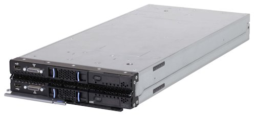
Figure 1. The Flex System x222 Compute Node
Did you know?
Flex System is a new category of computing that integrates multiple server architectures, networking, storage, and system management capability in to a single system that is easy to deploy and manage. Flex System has full and built-in virtualization support of servers, storage, and networking to speed provisioning and increased resiliency. In addition, it supports open industry standards, such as operating systems, networking and storage fabrics, virtualization, and system management protocols, to easily fit within existing and future data center environments. Flex System is scalable and extendable with multigenerational upgrades to protect and maximize IT investments.
Key features
The Flex System x222 Compute Node is a high-density offering that is designed to maximize the computing power that is available in the data center. With a balance between cost and system features, the x222 is an ideal platform for dense workloads, such as virtualization. This section describes the key features of the x222.
Scalability and performance
The x222 offers numerous features to boost performance, improve scalability, and reduce costs:
- Two independent servers in one mechanical package to maximize computing capacity.
- Powered by the Intel Xeon processor E5-2400 product family to improve productivity by offering affordable dual-socket system performance with eight-core processors with up to 2.3 GHz core speeds, up to 20 MB of L3 cache, and one QPI interconnect link of up to 8 GTps.
- Up to two processors in each server, 16 cores total, and 32 threads maximize the concurrent execution of multithreaded applications.
- Intelligent and adaptive system performance with Intel Turbo Boost Technology 2.0 allows processor cores to run at maximum speed during peak workloads by temporarily going beyond processor Thermal Design Power (TDP).
- Intel Hyper-Threading Technology boosts performance for multithreaded applications by enabling simultaneous multithreading within each processor core, up to two threads per core.
- Intel Virtualization Technology integrates hardware-level virtualization hooks that allow operating system vendors to better use the hardware for virtualization workloads.
- Intel Advanced Vector Extensions (AVT) improve floating-point performance for compute-intensive technical and scientific applications compared to Intel Xeon 5600 series processors.
- There are 12 DIMM sockets in each server, which support low profile (LP) RDIMMs and LRDIMMs, with a total capacity of up 384 GB using 32 GB LRDIMMs.
- Supports memory speeds of up to 1600 MHz to maximize memory performance.
- Support for 2.5-inch and 1.8-inch solid-state drives (SSDs) to maximize I/O operations per second (IOPS), which significantly improves application performance.
- The theoretical maximum memory bandwidth of the Intel Xeon processor E5-2400 product family is 38.4 GBps, which is 20% more than in the previous generation of Intel Xeon 5600 processors.
- The server offers PCI Express 3.0 I/O expansion capabilities that improve the theoretical maximum bandwidth by almost 100% (8 GTps per link using 128b/130b encoding) compared to the previous generation of PCI Express 2.0 (5 GTps per link using 8b/10b encoding)
- With Intel Integrated I/O Technology, the PCI Express 3.0 controller is integrated into the Intel Xeon processor E5 family. This integration reduces I/O latency and increases overall system performance.
Availability and serviceability
The x222 provides many features to simplify serviceability and increase system uptime:
- Chipkill, memory mirroring, and memory rank sparing for redundancy if there is a non-correctable memory failure.
- Tool-less cover removal provides easy access to upgrades and serviceable parts, such as processor, memory, and adapters.
- Use of optional 1.8-inch hot-swap drives allows for greater system uptime.
- Support for RAID 1 across the two drives installed in a server, as of Flex System code base 1.3.2 (announced May 13, 2014).
- A light path diagnostics panel and individual light path LEDs lead the technician to failed (or failing) components. These features simplify servicing, speed up problem resolution, and help improve system availability.
- Predictive Failure Analysis (PFA) detects when system components (such as processors, memory, and hard disk drives) operate outside of standard thresholds and generates proactive alerts in advance of possible failure, therefore increasing uptime.
- Solid-state drives (SSDs), which offer significantly better reliability than traditional mechanical HDDs for greater uptime.
- A built-in Integrated Management Module II (IMM2) continuously monitors system parameters, triggers alerts, and performs recovery actions in case of failures to minimize downtime.
- Built-in diagnostic tests using Dynamic Systems Analysis (DSA) Preboot speed up troubleshooting tasks to reduce service time.
- Three-year customer replaceable unit and onsite limited warranty, next business day 9x5. Optional service upgrades are available.
Manageability and security
Powerful systems management features simplify local and remote management of the x222:
- Each server includes an Integrated Management Module II (IMM2) to monitor server availability and perform remote management.
- An integrated industry-standard Unified Extensible Firmware Interface (UEFI) enables improved setup, configuration, and updates, and simplifies error handling.
- Integrated Trusted Platform Module (TPM) V1.2 support enables advanced cryptographic functionality, such as digital signatures and remote attestation.
- Industry-standard AES NI support for faster and stronger encryption.
- Integrates with the Flex System Manager™ for proactive systems management. It offers comprehensive systems management for the entire Flex System platform, increasing uptime, reducing costs, and improving productivity through advanced server management capabilities.
- Fabric Manager simplifies the deployment of infrastructure connections by managing network and storage address assignments.
- Intel Execute Disable Bit functionality can help prevent certain classes of malicious buffer overflow attacks when combined with a supporting operating system.
- Intel Trusted Execution Technology provides enhanced security through hardware-based resistance to malicious software attacks, allowing an application to run in its own isolated space protected from all other software running on a system.
Energy efficiency
The x222 offers the following energy-efficiency features to save energy, reduce operational costs, increase energy availability, and contribute to a green environment:
- The x222 is Energy Star 2.0 compliant. Energy Star is the trusted, US government-backed symbol for energy efficiency, with the goal of helping customers save money and protect the environment through energy efficient products and practices. For the Power and Performance Data Sheet, see http://ibm.com/systems/x/hardware/energy-star
- The component-sharing design of the Flex System chassis provides ultimate power and cooling savings.
- The Intel Xeon processor E5-2400 product family offers better performance over the previous generation while fitting in to the same TDP limits.
- Intel Intelligent Power Capability powers individual processor elements on and off as needed to reduce power draw.
- Low-voltage Intel Xeon processors draw less energy to satisfy the demands of power and thermally constrained data centers and telecommunication environments.
- Low-voltage 1.35 V DDR3 memory RDIMMs consume 15% less energy than 1.5 V DDR3 RDIMMs.
- Solid-state drives (SSDs) consume as much as 80% less power than traditional spinning 2.5-inch HDDs.
- The server uses hexagonal ventilation holes, a part of IBM Calibrated Vectored Cooling™ technology. Hexagonal holes can be grouped more densely than round holes, providing more efficient airflow through the system.
Locations of key components and connectors
The following figure shows the front of the server.
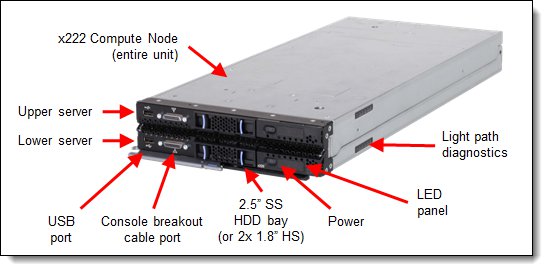
Figure 2. Front view of the Flex System x222 Compute Node
The following figure shows how the two servers connect together.
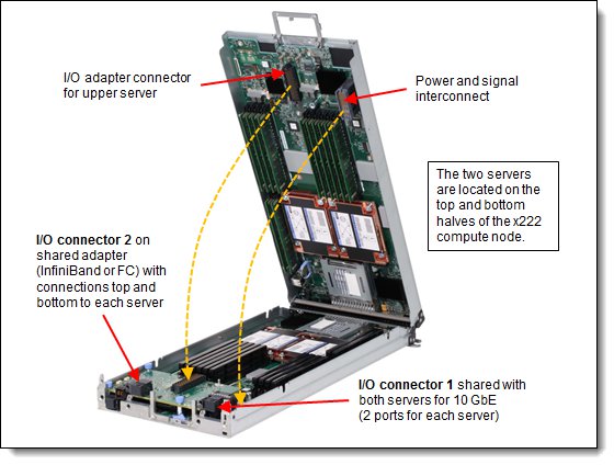
Figure 3. Open view of the Flex System x222 Compute Node
The following figure shows the locations of key components inside the upper server.
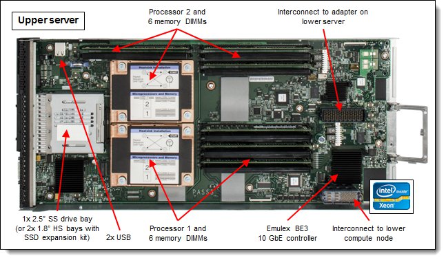
Figure 4. Inside view of the upper server
The following figure shows the locations of key components inside the lower server.
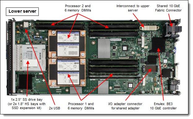
Figure 5. Inside view of the lower server
Standard specifications
The following table lists the standard specifications.
| Components | Specification |
| Form factor | Standard Flex System form factor with two independent servers. |
| Chassis support | Flex System Enterprise Chassis. |
| Processor | Up to four processors in a standard (half-width) Flex System form factor. Each server: Up to two Intel Xeon Processor E5-2400 product family CPUs with eight-core (up to 2.3 GHz) or six-core (up to 2.4 GHz) or quad-core (up to 2.2 GHz), one QPI link running at 8.0 GTps, L3 cache up to 20 MB, and memory speeds up to 1600 MHz. Note: The two servers are independent and cannot be combined to form a single four-socket system. |
| Chipset | Intel C600 series. |
| Memory | Up to 24 DIMM sockets in a standard (half-width) Flex System form factor. Each server: Up to 12 DIMM sockets (6 DIMMs per processor) using Low Profile (LP) DDR3 DIMMs. RDIMMs and LRDIMMs are supported. 1.5 V and low-voltage 1.35 V DIMMs are supported. There is support for up to 1600 MHz memory speed, depending on the processor. There are three memory channels per processor (two DIMMs per channel). Supports two DIMMs per channel operating at 1600 MHz (2 DPC @ 1600MHz) with single and dual rank RDIMMs. |
| Memory maximums | Each server: With LRDIMMs: Up to 384 GB with 12x 32 GB LRDIMMs and two processors With RDIMMs: Up to 192 GB with 12x 16 GB RDIMMs and two processors |
| Memory protection | ECC, Chipkill, optional memory mirroring, and memory rank sparing. |
| Disk drive bays | Each server: One 2.5" simple-swap SATA drive bay supporting SATA and SSD drives. Optional SSD mounting kit to convert a 2.5” simple-swap bay into two 1.8” hot-swap SSD bays. |
| Maximum internal storage | Each server: Up to 1 TB using a 2.5” SATA simple-swap drive or up to 1.6 TB using two 1.8” SSDs and the SSD Expansion Kit. |
| RAID support | Each server: RAID-0 or RAID-1 implemented via embedded ServeRAID C100 (as of Flex System code base 1.3.2, announced May 13, 2014). |
| Optical and tape bays | No internal bays; use an external USB drive. See http://support.lenovo.com/en/documents/pd011281 for options. |
| Network interfaces | Each server: Two 10 Gb Ethernet ports with Embedded 10Gb Virtual Fabric Ethernet LAN on motherboard (LOM) controller; Emulex BE3 based. Routes to chassis bays 1 and 2 through a Fabric Connector to the midplane. Features on Demand upgrade to FCoE and iSCSI. Usage of both ports on both system boards requires two scalable Ethernet switches in the chassis, each upgraded to enable 28 internal switch ports. |
| PCI Expansion slots | Each server: One connector for an I/O adapter; PCI Express 3.0 x16 interface. Supports special mid-mezzanine I/O cards that are shared by both system boards. Only one card is needed to connect both system boards. |
| Video | Each server: Matrox G200eR2 video core with 16 MB video memory that is integrated into IMM2. The maximum resolution is 1600x1200 at 75 Hz with 16 M colors. |
| Ports | Each server: One external, two internal USB ports for an embedded hypervisor. A console breakout cable port on the front of the server provides local KVM and serial ports (cable standard with chassis; additional cables optional). |
| Systems management | Each server: UEFI, Integrated Management Module II (IMM2) with Renesas SH7757 controller, Predictive Failure Analysis, light path diagnostics panel, automatic server restart, and remote presence. Support for Flex System Manager, IBM Systems Director, and the Lenovo ServerGuide. |
| Security features | Power-on password and admin password, Trusted Platform Module (TPM) 1.2. |
| Limited warranty | 3-year customer-replaceable unit and onsite limited warranty with 9x5/NBD. |
| Operating systems supported | Microsoft Windows Server, Red Hat Enterprise Linux, SUSE Linux Enterprise Server, VMware ESXi. See the Operating system support section for specifics. |
| Service and support | Optional country-specific service upgrades are available through ServicePacs: 6, 4, or 2-hour response time, 8-hour fix time, 1-year or 2-year warranty extension, remote technical support for Lenovo hardware and selected Lenovo and OEM software. |
| Dimensions | Width: 217 mm (8.6 in.), height: 56 mm (2.2 in.), depth: 492 mm (19.4 in.) |
| Weight | Maximum configuration: 8.2 kg (18 lb). |
The x222 servers are shipped with the following items:
- Statement of Limited Warranty
- Important Notices
- Documentation CD that contains the Installation and User's Guide
Standard models
The following table lists the standard models. The components that are listed for each model are for the entire x222 (half for each server).
Table 2. Standard models
| Model | Intel Xeon processors (2 max per server, 4 total)* |
Memory (12 max per server, 24 total)* |
Disk adapter (1 per server) |
Disk bays (1 per server)* |
Disks | Networking* (2 per server) |
I/O slots (used/ max) |
| 7916-A2x | 2x E5-2418L 4C 2.0GHz 10MB 1333MHz 50W |
2x 8 GB 2Rx4 (1333 MHz)** |
SATA (non-RAID) |
2x 2.5” SS | Open | 4x 10 GbE | 0 / 1 |
| 7916-B2x | 2x E5-2430L 6C 2.0GHz 15MB 1333MHz 60W |
2x 8 GB 2Rx4 (1333 MHz)** |
SATA (non-RAID) |
2x 2.5” SS | Open | 4x 10 GbE | 0 / 1 |
| 7916-C2x | 2x E5-2450L 8C 1.8GHz 20MB 1600MHz 70W |
2x 8 GB 2Rx4 1600 MHz |
SATA (non-RAID) |
2x 2.5” SS | Open | 4x 10 GbE | 0 / 1 |
| 7916-D2x | 2x E5-2403 4C 1.8GHz 10MB 1066MHz 80W |
2x 8 GB 2Rx4 (1066 MHz)** |
SATA (non-RAID) |
2x 2.5” SS | Open | 4x 10 GbE | 0 / 1 |
| 7916-F2x | 2x E5-2407 4C 2.2GHz 10MB 1066MHz 80W |
2x 8 GB 2Rx4 (1066 MHz)** |
SATA (non-RAID) |
2x 2.5” SS | Open | 4x 10 GbE | 0 / 1 |
| 7916-G2x | 2x E5-2420 6C 1.9GHz 15MB 1333MHz 95W |
2x 8 GB 2Rx4 (1333 MHz)** |
SATA (non-RAID) |
2x 2.5” SS | Open | 4x 10 GbE | 0 / 1 |
| 7916-H2x | 2x E5-2430 6C 2.2GHz 15MB 1333MHz 95W |
2x 8 GB 2Rx4 (1333 MHz)** |
SATA (non-RAID) |
2x 2.5” SS | Open | 4x 10 GbE | 0 / 1 |
| 7916-H6x | 2x E5-2430 6C 2.2GHz 15MB 1333MHz 95W |
2x 8 GB 2Rx4 (1333 MHz)** |
SATA (non-RAID) |
2x 2.5” SS | Open | 4x 10 GbE 2x InfiniBand† |
1 / 1 |
| 7916-J2x | 2x E5-2440 6C 2.4GHz 15MB 1333MHz 95W |
2x 8 GB 2Rx4 (1333 MHz)** |
SATA (non-RAID) |
2x 2.5” SS | Open | 4x 10 GbE | 0 / 1 |
| 7916-M2x | 2x E5-2450 8C 2.1GHz 20MB 1600MHz 95W |
2x 8 GB 2Rx4 1600 MHz |
SATA (non-RAID) |
2x 2.5” SS | Open | 4x 10 GbE | 0 / 1 |
| 7916-N2x | 2x E5-2470 8C 2.3GHz 20MB 1600MHz 95W |
2x 8 GB 2Rx4 1600 MHz |
SATA (non-RAID) |
2x 2.5” SS | Open | 4x 10 GbE | 0 / 1 |
* The quantities here are for the entire x222 Compute Node, half for each server. For example, each x222 model ships with two processors as standard, one installed in each of the two servers.
** The 1600 MHz memory DIMMs that are standard in these models operate at most at 1333 MHz or 1066 MHz as indicated, matching the memory speed of the processor.
† Model H6x includes the Flex System IB6132D 2-port FDR InfiniBand Adapter.
Chassis support
The x222 is supported in the Flex System Enterprise Chassis.
Up to 14 x222 Compute Nodes can be installed in the chassis, allowing a total of 28 servers to be deployed in 10U of rack space. The actual number of x222 Compute Nodes that can be installed in a chassis depends on these factors:
- The TDP power rating for the processors that are installed in the x222
- The number of power supplies installed
- The capacity of the power supplies installed (2100 W or 2500 W)
- The power redundancy policy used (N+1 or N+N)
The following table provides guidelines about what number of x222 Compute Nodes can be installed. For more guidance, use the Power Configurator, found at the following website:
http://ibm.com/systems/bladecenter/resources/powerconfig.html
In the table:
- Green = No restriction to the number of x222 Compute Nodes that are installable
- Yellow = Some bays must be left empty in the chassis
Table 3. Maximum number of x222 Compute Nodes installable based on power supplies installed and power redundancy policy used
| x222 TDP rating |
2100 W power supplies installed
|
2500 W power supplies installed
|
||||||
| N+1, N=5 6 power supplies |
N+1, N=4 5 power supplies |
N+1, N=3 5 power supplies |
N+N, N=3 6 power supplies |
N+1, N=5 6 power supplies |
N+1, N=4 5 power supplies |
N+1, N=3 4 power supplies |
N+N, N=3 6 power supplies |
|
| 50W | 14 | 14 | 13 | 14 | 14 | 14 | 14 | 14 |
| 60W | 14 | 14 | 12 | 13 | 14 | 14 | 14 | 14 |
| 70W | 14 | 14 | 11 | 12 | 14 | 14 | 14 | 14 |
| 80W | 14 | 14 | 10 | 11 | 14 | 14 | 13 | 14 |
| 95W | 14 | 13 | 9 | 10 | 14 | 14 | 12 | 13 |
Expansion Node support
The x222 does not support the Flex System Storage Expansion Node or the Flex System PCIe Expansion Node.
Processor options
The x222 supports the processor options that are listed in the following table. The x222 supports up to four Intel Xeon E5-2400 processors, one or two in each independent server. All four processors that are used in an x222 must be identical.
Note: The two servers are independent and cannot be combined to form a single four-socket system.
The table also shows which server models have each processor as standard. If no corresponding where used model for a particular processor is listed, then this processor is available only through the configure-to-order (CTO) process.
Table 3. Processor options
| Part number |
Feature code* | Intel Xeon processor description | Models where used |
| Intel Xeon processors | |||
| 00D1266 | A35X / A370 | Intel Xeon E5-2403 4C 1.8GHz 10MB 1066MHz 80W | D2x |
| 00D1265 | A35W / A36Z | Intel Xeon E5-2407 4C 2.2GHz 10MB 1066MHz 80W | F2x |
| 00D1264 | A35V / A36Y | Intel Xeon E5-2420 6C 1.9GHz 15MB 1333MHz 95W | G2x |
| 00D1263 | A35U / A36X | Intel Xeon E5-2430 6C 2.2GHz 15MB 1333MHz 95W | H2x, H6x |
| 00D1262 | A35T / A36W | Intel Xeon E5-2440 6C 2.4GHz 15MB 1333MHz 95W | J2x |
| 00D1261 | A35S / A36V | Intel Xeon E5-2450 8C 2.1GHz 20MB 1600MHz 95W | M2x |
| 00D1260 | A35R / A36U | Intel Xeon E5-2470 8C 2.3GHz 20MB 1600MHz 95W | N2x |
| Intel Xeon processors - Low power | |||
| 00D1269 | A360 / A373 | Intel Xeon E5-2418L 4C 2.0GHz 10MB 1333MHz 50W | A2x |
| 00D1271 | A362 / A375 | Intel Xeon E5-2428L 6C 1.8GHz 15MB 1333MHz 60W | - |
| 00D1268 | A35Z / A372 | Intel Xeon E5-2430L 6C 2.0GHz 15MB 1333MHz 60W | B2x |
| 00D1270 | A361 / A374 | Intel Xeon E5-2448L 8C 1.8GHz 20MB 1333MHz 70W | - |
| 00D1267 | A35Y / A371 | Intel Xeon E5-2450L 8C 1.8GHz 20MB 1600MHz 70W | C2x |
* The first feature code is for processor 1 and the second feature code is for processor 2.
Memory options
Lenovo DDR3 memory is compatibility tested and tuned for optimal performance and throughput. Memory specifications are integrated into the light path diagnostics panel for immediate system performance feedback and optimum system uptime. From a service and support standpoint, Lenovo memory automatically assumes the Lenovo system warranty, and Lenovo provides service and support worldwide.
The servers in the x222 supports Low Profile (LP) DDR3 memory RDIMMs and LRDIMMs. UDIMMs are not supported. Each of the two servers in the x222 has 12 DIMM sockets. Each server supports up to six DIMMs when one processor is installed and up to 12 DIMMs when two processors are installed. Each processor has three memory channels, and there are two DIMMs per channel.
The following rules apply when you select the memory configuration:
- The memory configurations on the two servers in the x222 can be different, however for factory orders, the initial memory configuration selected must be identical.
- Mixing 1.5 V and 1.35 V DIMMs in the same server is supported. In such a case, all DIMMs operate at 1.5 V.
- The maximum number of ranks that are supported per channel is eight.
- The maximum quantity of DIMMs that can be installed in each server in the x222 depends on the number of processors, as shown in the "Max. qty supported" row in the following table.
- All DIMMs in all processor memory channels operate at the same speed, which is determined as the lowest value of the following situations:
- The memory speed that is supported by a specific processor.
- The lowest maximum operating speed for the selected memory configuration that depends on the rated speed, as shown under the "Max. operating speed" section in the following table. The shaded cells indicate that the speed that is indicated is the maximum speed that the DIMM allows.
The following table shows the maximum memory speeds that are achievable based on the installed DIMMs and the number of DIMMs per channel. The table also shows the maximum memory capacity at any speed that is supported by the DIMM and the maximum memory capacity at the rated DIMM speed. In the table, cells that are highlighted with a gray background indicate when the specific combination of DIMM voltage and number of DIMMs per channel still allows the DIMMs to operate at rated speed.
Note: The quantities and capacities are for one server (that is, half of the x222). The maximums for the entire x222 (both servers) is double these numbers.
Table 4. Maximum memory speeds
| Spec |
RDIMMs
|
LRDIMMs
|
||||||
| Rank | Single rank | Dual rank | Quad rank | |||||
| Part numbers | 49Y1406 (4 GB) | 49Y1559 (4 GB) | 49Y1407 (4 GB) 49Y1397 (8 GB) 49Y1563 (16 GB) |
90Y3178 (4 GB) 90Y3109 (8 GB) 00D4968 (16GB) |
90Y3105 (32 GB) | |||
| Rated speed | 1333 MHz | 1600 MHz | 1333 MHz | 1600 MHz | 1333 MHz | |||
| Rated voltage | 1.35 V | 1.5 V | 1.35 V | 1.5 V | 1.35 V | |||
| Operating voltage |
1.35 V | 1.5 V | 1.5 V | 1.35 V | 1.5 V | 1.5 V | 1.35 V | 1.5 V |
| Max quantity* | 12 | 12 | 12 | 12 | 12 | 12 | 12 | 12 |
| Largest DIMM | 4 GB | 4 GB | 4 GB | 16 GB | 16 GB | 16 GB | 32 GB | 32 GB |
| Max memory capacity |
48 GB | 48 GB | 48 GB | 192 GB | 192 GB | 192 GB | 384 GB | 384 GB |
| Max memory at rated speed |
48 GB | 48 GB | 48 GB | 192 GB | 192 GB | 192 GB | N/A | 192 GB |
| Maximum operating speed (MHz) | ||||||||
| 1 DIMM per channel |
1333 MHz | 1333 MHz | 1600 MHz | 1333 MHz | 1333 MHz | 1600 MHz | 1066 MHz | 1333 MHz |
| 2 DIMMs per channel |
1333 MHz | 1333 MHz | 1600 MHz | 1333 MHz | 1333 MHz | 1600 MHz | 1066 MHz | 1066 MHz |
* The maximum quantity that is supported is shown for two installed processors. When one processor is installed, the maximum quantity that is supported is half of that shown.
Install DIMM fillers in all empty DIMM sockets to ensure proper airflow.
The following memory protection technologies are supported:
- ECC
- Chipkill (for x4-based memory DIMMs; look for "x4" in the DIMM description)
- Memory mirroring
- Memory sparing
If memory mirroring is used, then the DIMMs must be installed in pairs (minimum of one pair per processor), and both DIMMs in a pair must be identical in type and size.
If memory rank sparing is used, then a minimum of one quad-rank DIMM or two single-rank or dual-rank DIMMs must be installed per populated channel (the DIMMs do not need to be identical). In rank sparing mode, one rank of a DIMM in each populated channel is reserved as spare memory. The size of a rank varies depending on the DIMMs that are installed.
The following table lists the memory options that are available for the x222. DIMMs can be installed one at a time in each server, but for performance reasons, install them in sets of three (one for each of the three memory channels).
Table 5. Memory options for the x222
| Part number |
Feature code |
Description | Models where used |
| Registered DIMMs (RDIMMs) - 1333 MHz | |||
| 49Y1406 | 8941 | 4GB (1x4GB, 1Rx4, 1.35V) PC3L-10600 CL9 ECC DDR3 1333MHz LP RDIMM | - |
| 49Y1407 | 8942 | 4GB (1x4GB, 2Rx8, 1.35V) PC3L-10600 CL9 ECC DDR3 1333MHz LP RDIMM | - |
| 49Y1397 | 8923 | 8GB (1x8GB, 2Rx4, 1.35V) PC3L-10600 CL9 ECC DDR3 1333MHz LP RDIMM | - |
| 49Y1563 | A1QT | 16GB (1x16GB, 2Rx4, 1.35V) PC3L-10600 CL9 ECC DDR3 1333MHz LP RDIMM | - |
| Registered DIMMs (RDIMMs) - 1600 MHz | |||
| 49Y1559 | A28Z | 4GB (1x4GB, 1Rx4, 1.5V) PC3-12800 CL11 ECC DDR3 1600MHz LP RDIMM | - |
| 90Y3178 | A24L | 4GB (1x4GB, 2Rx8, 1.5V) PC3-12800 CL11 ECC DDR3 1600MHz LP RDIMM | - |
| 90Y3109 | A292 | 8GB (1x8GB, 2Rx4, 1.5V) PC3-12800 CL11 ECC DDR3 1600MHz LP RDIMM | All models |
| 00D4968 | A2U5 | 16GB (1x16GB, 2Rx4, 1.5V) PC3-12800 CL11 ECC DDR3 1600MHz LP RDIMM | - |
| Load-reduced DIMMs (LRDIMMs) | |||
| 90Y3105 | A291 | 32GB (1x32GB, 4Rx4, 1.35V) PC3L-10600 CL9 ECC DDR3 1333MHz LP LRDIMM | - |
Internal disk storage options
The x222 has two 2.5-inch simple-swap drive bays that are accessible from the front of the unit (Figure 2), with one bay for each of the servers. Each server offers a 6 Gbps SATA controller that is implemented by the Intel C600 chipset. As of Flex System code base 1.3.2 (announced May 13, 2014), the ServeRAID C100 embedded RAID controller is enabled which provides firmware-based RAID capabilities.
The 2.5-inch drive bays support SATA hard disk drives (HDDs) or SATA solid-state drives (SSDs). Each server in the x222 optionally supports 1.8-inch SSDs by first installing the Flex System SSD Expansion Kit in to the 2.5-inch bay. This kit then provides two 1.8-inch hot-swap drive bays.
The ServeRAID C100 is an integrated SATA controller with RAID capabilities. When enabled in a server in the x222 with two 1.8-inch SSDs, the RAID-1 feature of the C100 offers a cost-effective way to provide fault-tolerant disk subsystem management to help safeguard your valuable data and enhance availability.
The ServeRAID C100 has the following specifications:
- Supports RAID levels 0, 1
- Supports 3 Gbps SATA ports
- Support for up to two virtual drives
- Support for virtual drive sizes greater than 2 TB
- Fixed stripe unit size of 64 KB
- Support for MegaRAID Storage Manager management software
The storage configurations on the two servers in the x222 can be different, however for factory orders, the initial storage configuration selected must be identical.
The following table lists the supported drives.
| Part number |
Feature code |
Description | Maximum per server* |
| 1.8-inch drive expansion kit | |||
| 00W0366 | A3HV | Flex System SSD Expansion Kit (used to convert the 2.5-inch bay in to two 1.8-inch bays) |
1 |
| 1.8-inch Enterprise SSDs | |||
| 00W1120 | A3HQ | 100GB SATA 1.8" MLC Enterprise SSD | 2 |
| 49Y6119 | A3AN | 200GB SATA 1.8" MLC Enterprise SSD | 2 |
| 1.8-inch Enterprise Value SSDs | |||
| 00AJ040 | A4KV | S3500 80GB SATA 1.8" MLC Enterprise Value SSD | 2 |
| 00AJ045 | A4KW | S3500 240GB SATA 1.8" MLC Enterprise Value SSD | 2 |
| 00AJ050 | A4KX | S3500 400GB SATA 1.8" MLC Enterprise Value SSD | 2 |
| 00AJ455 | A58U | S3500 800GB SATA 1.8" MLC Enterprise Value SSD | 2 |
| 00AJ335 | A56V | 120GB SATA 1.8" MLC Enterprise Value SSD | 2 |
| 00AJ340 | A56W | 240GB SATA 1.8" MLC Enterprise Value SSD | 2 |
| 00AJ345 | A56X | 480GB SATA 1.8" MLC Enterprise Value SSD | 2 |
| 00AJ350 | A56Y | 800GB SATA 1.8" MLC Enterprise Value SSD | 2 |
| 2.5-inch HDDs drives | |||
| 90Y8974 | A369 | 500GB 7.2K 6Gbps SATA 2.5'' G2 SS HDD | 1 |
| 90Y8979 | A36A | 1TB 7.2K 6Gbps SATA 2.5'' G2 SS HDD | 1 |
| 2.5-inch Enterprise SSDs | |||
| 90Y8994 | A36D | 100GB SATA 2.5” MLC Enterprise SSD for Flex System x222 | 1 |
| 00AJ320 | A51S | S3700 400GB SATA 2.5" MLC Enterprise SSD for Flex System x222 | 1 |
| 00AJ325 | A51T | S3700 800GB SATA 2.5" MLC Enterprise SSD for Flex System x222 | 1 |
| 2.5-inch Enterprise Value SSDs | |||
| 00AJ330 | A51U | S3500 480GB SATA 2.5" MLC Enterprise Value SSD Flex System x222 | 1 |
| 00AJ415 | A57B | 120GB SATA 2.5" MLC Enterprise Value SSD for Flex System x222 | 1 |
| 00AJ420 | A57C | 240GB SATA 2.5" MLC Enterprise Value SSD for Flex System x222 | 1 |
| 00AJ425 | A57D | 480GB SATA 2.5" MLC Enterprise Value SSD for Flex System x222 | 1 |
| 00AJ430 | A57E | 800GB SATA 2.5" MLC Enterprise Value SSD for Flex System x222 | 1 |
* The quantities that are listed here are for each of the two servers in the x222.
Internal tape drives
The x222 does not support an internal tape drive. However, it can be attached to external tape drives by using Fibre Channel connectivity.
Optical drives
The server does not support an internal optical drive option, however, you can connect an external USB optical drive. See http://support.lenovo.com/en/documents/pd011281 for information about available external optical drives from Lenovo.
Note: The USB port on the compute nodes supply up to 0.5 A at 5 V. For devices that require more power, an additional power source will be required.
Embedded 10Gb Virtual Fabric Adapter
Each server in the x222 includes an Embedded two-port 10Gb Virtual Fabric Adapter (VFA, also known as LAN on Motherboard or LOM) built in to the system board. The x222 has one Fabric Connector (which is physically on the lower server) and the Ethernet connections from both Embedded 10 Gb VFAs are routed through it. Figure 5 shows the physical location of the Fabric Connector.
The following figure shows the internal connections between the Embedded 10Gb VFAs and the switches in chassis bays 1 and 2.
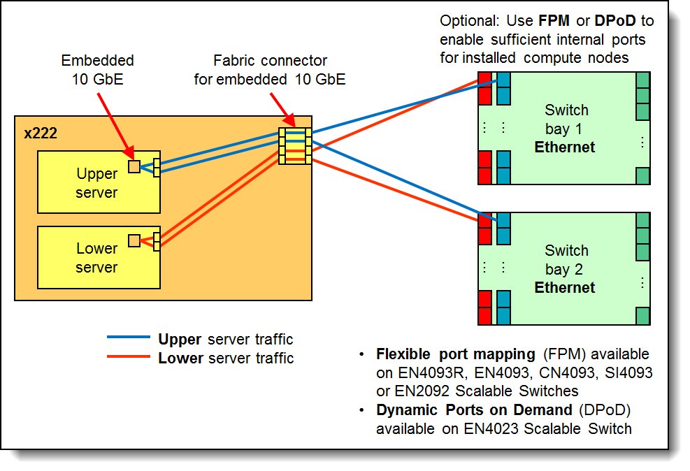
Figure 6. Embedded two-port 10 Gb VFA connectivity to the switches
In the figure:
- The blue lines show that the two Ethernet ports in the upper server route to switches in bay 1 and bay 2.
- The red lines show that the two Ethernet ports in the lower server also route to switches in bay 1 and bay 2.
To support both servers in the x222 you will need sufficient internal ports, either by applying the relevant switch upgrade, or using flexible port mapping or Dynamic Ports on Demand to reconfigure the ports.
Flexible port mapping (CN4093, EN4093R, EN4093, SI4093, EN2092) or Dynamic Ports on Demand (EN4023) both allow you to select which ports (internal or external) are enabled. The base switch has 24 port licenses and these ports can be assigned to either internal or external ports. Each x222 installed in the chassis requires 2 internal ports to each switch. If you have eleven x222 compute nodes installed in the chassis then that will require 22 port licenses just for internal ports, leaving 2 port licenses for external ports. For more than 11 compute nodes or for additional external ports, you will need to purchase additional upgrades.
For a list of supported Ethernet switches, see the Supported switches section.
The Embedded 10Gb VFA is based on the Emulex BladeEngine 3 (BE3), which is a single-chip, dual-port 10 Gigabit Ethernet (10GbE) Ethernet Controller. These are some of the features of the Embedded 10Gb VFA:
- Two 10Gb Ethernet ports
- PCI-Express Gen2 x8 host bus interface
- Supports multiple virtual NIC (vNIC) functions
- TCP/IP Offload Engine (TOE enabled)
- SR-IOV capable
- RDMA over TCP/IP capable
- iSCSI and FCoE upgrade offering through FoD
The following table lists the ordering information for the Features on Demand upgrade which enables the iSCSI and FCoE support on the Embedded 10Gb Virtual Fabric Adapter.
Two licenses required: To enable the FCoE/iSCSI upgrade for both servers in the x222 Compute Node, two licenses are required.
Table 7. Feature on Demand upgrade for FCoE and iSCSI support
| Part number | Feature code |
Description | Maximum supported* |
| 90Y9310 | A2TD | IBM Virtual Fabric Advanced Software Upgrade (LOM) | 1 per server 2 per x222 Compute Node |
* To enable the FCoE/iSCSI upgrade for both servers in the x222 Compute Node, two licenses are required.
Network and storage adapters
In addition to the Embedded 10GbE VFAs on each server, the x222 supports one I/O adapter that is shared between the two servers and is routed to the I/O Modules that are installed in bays 3 and 4 of the chassis.
The shared I/O adapter is mounted in the lower server, as shown in the following figure. The adapter has two host interfaces, one on either side, for connecting to the servers. Each host interface is PCI Express 3.0 x16.
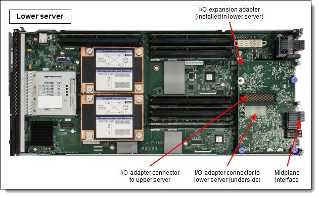
Figure 7. Location of the I/O adapter
The following table lists the supported network and storage adapter. Adapters are shared between the two servers with half the ports routing to each server.
| Part number | Feature code |
Description | Number of ports |
Maximum supported |
| InfiniBand | ||||
| 90Y3486 | A365 | Flex System IB6132D 2-port FDR InfiniBand Adapter | 2 | 1* |
| Fibre Channel | ||||
| 95Y2379 | A3HU | Flex System FC5024D 4-port 16Gb FC Adapter | 4 | 1* |
* One adapter is supported per x222. The adapter is shared between the two servers.
A compatible switch module must be installed in the corresponding I/O bays in the chassis, as indicated in the following table. Installing four switches in all four switch bays of the chassis means that all ports of the adapter are enabled, which improves performance and network availability.
Table 9. Adapter to I/O bay correspondence
| Server | Adapter |
With
FC5024D 4-port |
With
IB6132D 2-port |
Corresponding I/O module bay in the chassis |
| Upper server | Embedded 10 GbE Virtual Fabric Adapter |
Port 1 | Module bay 1 | |
| Port 2 | Module bay 2 | |||
| Lower server | Embedded 10 GbE Virtual Fabric Adapter |
Port 1 | Module bay 1 | |
| Port 2 | Module bay 2 | |||
| Upper server | I/O Expansion adapter FC5024D 4-port 16Gb FC or IB6132D 2-port FDR InfiniBand |
Port 1 | Not used | Module bay 3 |
| Port 2 | Port 1 | Module bay 4 | ||
| Lower server | Port 1 | Port 1 | Module bay 3 | |
| Port 2 | Not used | Module bay 4 | ||
The FC5024D is a four-port adapter where two ports are routed to each server. Port 1 of each server is connected to the switch in bay 3 and Port 2 of each server is connected to the switch in bay 4. To take advantage of all four ports, you must install a supported Fibre Channel switch in both switch bays.
The following figure shows how the FC5024D 4-port 16 Gb FC adapter and the Embedded 10Gb VFAs are connected to the Ethernet and Fibre Channel switches installed in the chassis.
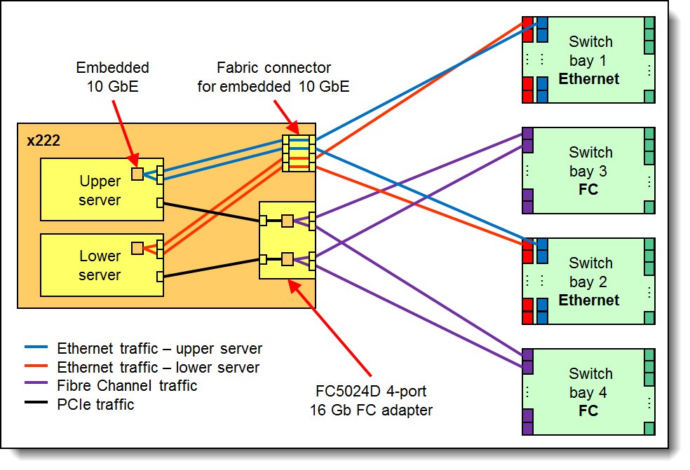
Figure 8. Logical layout of the interconnects - Ethernet and Fibre Channel
The IB6132D is a two-port adapter and has one port that is routed to each server. One port of the adapter connects to the InfiniBand switch in switch bay 3 and the other adapter port connects to the InfiniBand switch in switch bay 4 in the chassis. The IB6132D requires that two InfiniBand switches be installed in the chassis.
The following figure shows how the IB6132D 2-port FDR InfiniBand adapter and the four ports of the two Embedded 10 GbE VFAs are connected to the Ethernet and InfiniBand switches that are installed in the chassis.
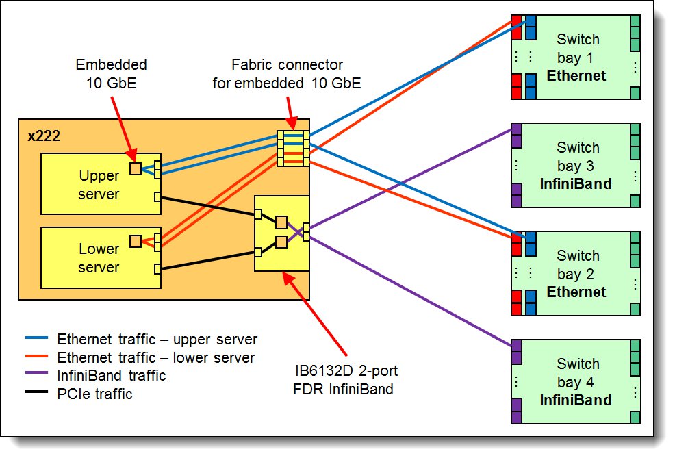
Figure 9. Logical layout of the interconnects - Ethernet and InfiniBand
Supported switches
The following table shows which Ethernet, Fibre Channel, and InfiniBand switches are supported:
Table 10. Supported switches
| Adapter | Switches supported | Switch upgrades |
| Embedded 10 GbE Virtual Fabric Adapter |
EN2092 1Gb Ethernet Scalable Switch (49Y4294) | Switch port licenses can be used for internal or external ports using flexible port mapping or using Dynamic Ports on Demand. Additional ports may be needed depending on your configuration. See the switch Product Guide** |
| EN4093 10Gb Scalable Switch (49Y4270)* | ||
| EN4093R 10Gb Scalable Switch (95Y3309) | ||
| CN4093 10Gb Converged Scalable Switch (00D5823) | ||
| SI4093 System Interconnect Module (95Y3313) | ||
| EN4023 10Gb Scalable Switch (94Y5212) | ||
| FC5024D 4-port 16Gb FC Adapter |
FC5022 16Gb SAN Scalable Switch (88Y6374) | Switch port licenses can be used for internal or external ports. Additional ports may be needed depending on your configuration. See the FC5022 Product Guide† |
| FC5022 24-port 16Gb SAN Scalable Switch (00Y3324) | ||
| FC5022 24-port 16Gb ESB SAN Scalable Switch (90Y9356) | ||
| IB6132D 2-port FDR InfiniBand Adapter |
IB6131 InfiniBand Switch (90Y3450) | No upgrade required‡ |
* Withdrawn from marketing
** Product Guides for Flex System switches can be found at: https://lenovopress.com/servers/blades/networkmodule
† Product Guides for the Flex System FC5022 SAN Scalable Switch can be found at:
http://lenovopress.com/tips0870
‡ A switch upgrade is not required to activate the necessary ports. However, to run the ports at FDR speeds, you need the FDR upgrade 90Y3462.
The following switches are not supported by the x222 because they do not provide enough internal ports to connect to both servers in the x222 Compute Node:
- Flex System EN4091 10Gb Ethernet Pass-thru Module
- Flex System FC3171 8Gb SAN Switch
- Flex System FC3171 8Gb SAN Pass-thru
- Flex System EN6131 40Gb Ethernet Switch
- Cisco Nexus B22 Fabric Extender
Power supplies
Server power is derived from the power supplies that are installed in the chassis. There are no server options regarding power supplies. Support for the x222 might be affected by the choice of the power supply that is installed in the chassis, as described in the Chassis support section.
Integrated virtualization
Each server in the x222 supports the ESXi hypervisor on a USB memory key through two internal USB ports (see Figure 3). The supported USB memory keys are listed in the following table.
There are two types of USB keys: preload keys or blank keys. Blank keys allow you to download a Lenovo customized version of ESXi and load it onto the key. Each server supports one or two keys that are installed, but only certain combinations:
Supported combinations:
- One preload key
- One blank key
- One preload key and one blank key
- Two blank keys
Unsupported combinations:
- Two preload keys
Installing two preload keys prevents ESXi from booting, as described at the website http://kb.vmware.com/kb/1035107. Having two keys that are installed provides a backup boot device. Both devices are listed in the boot menu, which allows you to boot from either device or to set one as a backup in case the first one becomes corrupted.
Table 11. Virtualization options
| Part number | Feature code |
Description | Maximum supported |
| 41Y8298 | A2G0 | Blank USB Memory Key for VMware ESXi Downloads | 2 |
| 41Y8307 | A383 | USB Memory Key for VMware ESXi 5.0 Update1 | 1 |
| 41Y8311 | A2R3 | USB Memory Key for VMware ESXi 5.1 | 1 |
| 41Y8382 | A4WZ | USB Memory Key for VMware ESXi 5.1 Update 1 | 1 |
| 41Y8385 | A584 | USB Memory Key for VMware ESXi 5.5 | 1 |
Light path diagnostics panel
For quick problem determination when you are physically at the server, the x222 Compute Node offers a three-step guided path:
- The Fault LED on the front panel of each server
- The light path diagnostics panels, one for each server, as shown in the following figure
- LEDs that are next to key components on the system board
The two light path diagnostics panels on the x222 are visible when you remove the server from the chassis. One panel is for the upper server and one is for the lower server.
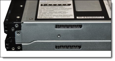
Figure 10. Location of x222 light path diagnostics panels
To illuminate the light path diagnostics LEDs, power off the server, slide it out of the chassis, and press the power button. The power button doubles as the light path diagnostics remind button when the server is removed from the chassis.
The meanings of the LEDs in the light path diagnostics panel are listed in the following table.
Table 12. Light path diagnostic panel LEDs
| LED | Meaning |
| LP | The light path diagnostics panel is operational. |
| S BRD | A system board error is detected. |
| MIS | A mismatch has occurred between the processors, DIMMs, or HDDs within the configuration (as reported by POST). |
| NMI | A non-maskable interrupt (NMI) has occurred. |
| TEMP | An over-temperature condition occurs that was critical enough to shut down the server. |
| MEM | A memory fault has occurred. The corresponding DIMM error LEDs on the system board are also lit. |
Remote management
The two servers in the x222 each contain an Integrated Management Module II (IMM2), which interfaces with the advanced management module in the chassis. The combination of these features provides advanced service-processor control, monitoring, and an alerting function. If an environmental condition exceeds a threshold or if a system component fails, LEDs on the system board are lit to help you diagnose the problem, the error is recorded in the event log, and you are alerted to the problem. A virtual presence capability comes standard for remote server management.
Remote server management is provided through industry-standard interfaces:
- Intelligent Platform Management Interface (IPMI) Version 2.0
- Simple Network Management Protocol (SNMP) Version 3
- Common Information Model (CIM)
- Web browser
Each server also supports virtual media and remote control features, which provide the following functions:
- Remotely viewing video with graphics resolutions up to 1600 x 1200 at 75 Hz with up to 23 bits per pixel, regardless of the system state
- Remotely accessing the server by using the keyboard and mouse from a remote client
- Mapping the CD or DVD drive, diskette drive, and USB flash drive on a remote client, and mapping ISO and diskette image files as virtual drives that are available for use by the server
- Uploading a diskette image to the IMM2 memory and mapping it to the server as a virtual drive
- Capturing blue-screen errors
Operating system support
The servers in the x222 Compute Node supports the following operating systems. The operating systems on the two servers in the x222 can be different, however for factory orders, the initial operating systems selected must be identical.
- Microsoft Windows Server 2008 Datacenter x64 SP2
- Microsoft Windows Server 2008 Enterprise x64 SP2
- Microsoft Windows Server 2008 R2 SP1
- Microsoft Windows Server 2008 Standard x64 SP2
- Microsoft Windows Server 2008 Web x64 SP2
- Microsoft Windows Server 2012
- Microsoft Windows Server 2012 R2
- Red Hat Enterprise Linux 5.10 Xen x64
- Red Hat Enterprise Linux 5.10 x64
- Red Hat Enterprise Linux 5.9 Xen x64
- Red Hat Enterprise Linux 5.9 x64
- Red Hat Enterprise Linux 6.4 x64
- Red Hat Enterprise Linux 6.5 x64
- Red Hat Enterprise Linux 6.6 x64
- Red Hat Enterprise Linux 6.7 x64
- Red Hat Enterprise Linux 6.8 x64
- Red Hat Enterprise Linux 7.0
- Red Hat Enterprise Linux 7.1
- Red Hat Enterprise Linux 7.2
- SUSE Linux Enterprise Server 11 Xen x64 SP2
- SUSE Linux Enterprise Server 11 Xen x64 SP3
- SUSE Linux Enterprise Server 11 Xen x64 SP4
- SUSE Linux Enterprise Server 11 x64 SP2
- SUSE Linux Enterprise Server 11 x64 SP3
- SUSE Linux Enterprise Server 11 x64 SP4
- SUSE Linux Enterprise Server 12
- SUSE Linux Enterprise Server 12 SP1
- SUSE Linux Enterprise Server 12 Xen
- SUSE Linux Enterprise Server 12 Xen SP1
- VMware ESX 4.1 U3
- VMware ESXi 5.0 U2
- VMware ESXi 5.0 U3
- VMware ESXi 5.1 U2
- VMware ESXi 5.1 U3
- VMware ESXi 5.1U1
- VMware ESXi 5.5
- VMware ESXi 5.5 U1
- VMware ESXi 5.5 U2
- VMware ESXi 5.5 U3
- VMware ESXi 6.0
For a complete list of supported, certified and tested operating systems, plus additional details and links to relevant web sites, see the Operating System Interoperability Guide: https://lenovopress.com/osig#servers=x222-7916
Physical specifications
Dimensions and weight (approximate):
- Width: 217 mm (8.6 in.)
- Height: 56 mm (2.2 in.)
- Depth: 492 mm (19.4 in.)
- Maximum weight: 8.2 kg (18 lb)
Shipping dimensions (approximate):
- Height: 197 mm (7.8 in.)
- Depth: 603 mm (23.7 in.)
- Width: 430 mm (16.9 in.)
Supported environment
The Flex System x222 server complies with ASHRAE Class A3 specifications when it is installed within the Flex System Enterprise Chassis.
Here is the supported operating environment:
Power on:
- Temperature: 5 - 40 °C (41 - 104 °F)
- Humidity, non-condensing: -12 °C dew point (10.4 °F) and 8 - 85% relative humidity
- Maximum dew point: 24 °C (75 °F)
- Maximum altitude: 3048 m (10,000 ft)
- Maximum rate of temperature change: 5 °C/hr (41 °F/hr)
Power off:
- Temperature: 5 - 45 °C (41 - 113 °F)
- Relative humidity: 8 - 85%
- Maximum dew point: 27 °C (80.6 °F)
Storage (non-operating):
- Temperature: 1 - 60 °C (33.8 - 140 °F)
- Altitude: 3050 m (10,006 ft)
- Relative humidity: 5 - 80%
- Maximum dew point: 29 °C (84.2°F)
Shipment (non-operating):
- Temperature: -40 - 60 °C (-40 - 140 °F)
- Altitude: 10,700 m (35,105 ft)
- Relative humidity: 5 - 100%
- Maximum dew point: 29 °C (84.2 °F)
Warranty options
The system has a three-year warranty with 24x7 standard call center support and 9x5 Next Business Day onsite coverage. Also available are Lenovo Services warranty maintenance upgrades and post-warranty maintenance agreements, with a well-defined scope of services, including service hours, response time, term of service, and service agreement terms and conditions.
Lenovo warranty service upgrade offerings are region-specific. Not all warranty service upgrades are available in every region. For more information about Lenovo warranty service upgrade offerings that are available in your region, go to the Data Center Advisor and Configurator website http://dcsc.lenovo.com, then do the following:
- In the Customize a Model box in the middle of the page, select the Services option in the Customization Option dropdown menu
- Enter in the machine type & model of the system
- From the search results, you can click either Deployment Services or Support Services to view the offerings
The following table explains warranty service definitions in more detail.
| Term | Description |
|---|---|
| On-site service | A service technician will arrive at the client’s location for equipment service. |
| 24x7x2 hour | A service technician is scheduled to arrive at the client’s location within two hours after remote problem determination is completed. Lenovo provides service around the clock, every day, including Lenovo holidays. |
| 24x7x4 hour | A service technician is scheduled to arrive at the client’s location within four hours after remote problem determination is completed. Lenovo provides service around the clock, every day, including Lenovo holidays. |
| 9x5x4 hour | A service technician is scheduled to arrive at the client’s location within four business hours after remote problem determination is completed. Lenovo provides service 8:00 am - 5:00 pm in the client's local time zone, Monday-Friday, excluding Lenovo holidays. For example, if a customer reports an incident at 3:00 pm on Friday, the technician will arrive by 10:00 am the following Monday. |
| 9x5 next business day | A service technician is scheduled to arrive at the client’s location on the business day after remote problem determination is completed. Lenovo provides service 8:00 am - 5:00 pm in the client's local time zone, Monday - Friday, excluding Lenovo holidays. Calls received after 4:00 pm local time require an extra business day for service dispatch. Next business day service is not guaranteed. |
| Committed Repair | Problems receive priority handling so that repairs are completed within the committed time of 6, 8, or 24 hours. Lenovo provides service 24 hours/day, every day, including Lenovo holidays. |
The following Lenovo warranty service upgrades are available:
- Warranty and maintenance service upgrades:
- Three, four, or five years of 9x5 or 24x7 service coverage
- Onsite response from next business day to 2 or 4 hours
- Committed repair service
- Warranty extension of up to 5 years
- Post warranty extensions
- Committed Repair Service
Committed Repair Services enhances the level of Warranty Service Upgrade or Post Warranty/Maintenance Service offering associated with the selected systems. Offerings vary and are available in select countries.
- Priority handling to meet defined time frames to restore the failing machine to good working condition
- Committed repair service levels are measured within the following coverage hours:
- 24x7x6: Service performed 24 hours per day, 7 days per week, within 6 hours
- 24x7x8: Service performed 24 hours per day, 7 days per week, within 8 hours
- 24x7x24: Service performed 24 hours per day, 7 days per week, within 24 hours
- Hard Disk Drive Retention
Lenovo’s Hard Disk Drive Retention (HDDR) service is a multi-drive hard drive retention offering that ensures your data is always under your control, regardless of the number of hard drives that are installed in your Lenovo server. In the unlikely event of a hard drive failure, you retain possession of your hard drive while Lenovo replaces the failed drive part. Your data stays safely on your premises, in your hands. The Hard Drive Retention service can be purchased in convenient bundles with our warranty upgrades and extensions.
- Microcode Support
Keeping microcode current helps prevent hardware failures and security exposure. There are two levels of service: analysis of the installed base and analysis and update where required. Offerings vary by region and can be bundled with other warranty upgrades and extensions.
- Remote Technical Support Services (RTS)
RTS provides comprehensive technical call center support for covered servers, storage, operating systems, and applications. Providing a single source for support of hardware and software issues, RTS can reduce problem resolution time, decreasing the cost to address technical problems and increasing uptime. Offerings are available for Windows, Linux, IBM Systems Director, VMware, Microsoft business applications, and Lenovo System x storage devices, and IBM OEM storage devices.
Regulatory compliance
The server conforms to the following standards:
- ASHRAE Class A3
- Energy Star 2.0
- FCC - Verified to comply with Part 15 of the FCC Rules Class A
- Canada ICES-004, issue 3 Class A
- UL/IEC 60950-1
- CSA C22.2 No. 60950-1
- NOM-019
- Argentina IEC 60950-1
- Japan VCCI, Class A
- IEC 60950-1 (CB Certificate and CB Test Report)
- China CCC (GB4943); (GB9254, Class A); (GB17625.1)
- Taiwan BSMI CNS13438, Class A; CNS14336
- Australia/New Zealand AS/NZS CISPR 22, Class A
- Korea KN22, Class A, KN24
- Russia/GOST ME01, IEC 60950-1, GOST R 51318.22, GOST R
- 51318.249, GOST R 51317.3.2, GOST R 51317.3.3
- IEC 60950-1 (CB Certificate and CB Test Report)
- CE Mark (EN55022 Class A, EN60950-1, EN55024, EN61000-3-2, and
- EN61000-3-3)
- CISPR 22, Class A
- TUV-GS (EN60950-1/IEC 60950-1, EK1-ITB2000)
Trademarks
Lenovo and the Lenovo logo are trademarks or registered trademarks of Lenovo in the United States, other countries, or both. A current list of Lenovo trademarks is available on the Web at https://www.lenovo.com/us/en/legal/copytrade/.
The following terms are trademarks of Lenovo in the United States, other countries, or both:
Lenovo®
Flex System
Lenovo Services
ServeRAID
ServerGuide
System x®
The following terms are trademarks of other companies:
Intel® and Xeon® are trademarks of Intel Corporation or its subsidiaries.
Linux® is the trademark of Linus Torvalds in the U.S. and other countries.
Microsoft®, Windows Server®, and Windows® are trademarks of Microsoft Corporation in the United States, other countries, or both.
Other company, product, or service names may be trademarks or service marks of others.


