

Top
Abstract
Many clients successfully use Ethernet and Fibre Channel connectivity from their servers to their LAN and SAN. These clients are seeking ways to reduce the cost and complexity of these environments by using the capabilities of Ethernet and Fibre Channel convergence.
The RackSwitch™ G8264CS top-of-rack switch offers the benefits of a converged infrastructure. As part of its forward thinking design, this switch has flexibility for future growth and expansion. This switch is ideal for clients who are looking to connect to existing SANs and clients who want native Fibre Channel connectivity, in addition to support for such protocols as Ethernet, Fibre Channel over Ethernet (FCoE), and iSCSI.
Notes:
- This Product Guide describes withdrawn models of the RackSwitch G8264CS that are no longer available for ordering that support Networking OS up to version 7.x.
- For currently available models of the Lenovo RackSwitch G8264CS that support Networking OS version 8.x onwards, see the Lenovo Press Product Guide Lenovo RackSwitch G8264CS.
Withdrawn from marketing: This networking switch is now withdrawn from marketing.
Introduction
Many clients successfully use Ethernet and Fibre Channel connectivity from their servers to their LAN and SAN. These clients are seeking ways to reduce the cost and complexity of these environments by using the capabilities of Ethernet and Fibre Channel convergence.
The RackSwitch™ G8264CS top-of-rack switch (shown in Figure 1) offers the benefits of a converged infrastructure. As part of its forward thinking design, this switch has flexibility for future growth and expansion. This switch is ideal for clients who are looking to connect to existing SANs and clients who want native Fibre Channel connectivity, in addition to support for such protocols as Ethernet, Fibre Channel over Ethernet (FCoE), and iSCSI.
The RackSwitch G8264CS includes the following highlights:
- Lossless Ethernet, Fibre Channel, and FCoE in one switch
- 36 SFP+ ports supporting 1 Gb or 10 Gb Ethernet
- Flexibility with 12 Omni Ports that support 10 Gb Ethernet or 4/8 Gb Fibre Channel connections
- Ideal for clients looking to aggregate FC or FCoE traffic with the ability to connect to existing SANs
- Future-proofed with four 40 Gb QSFP+ ports
- Low cost, low complexity, and simpler deployment and management
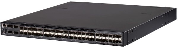
Figure 1. RackSwitch G8264CS
Did you know?
The RackSwitch G8264CS simplifies deployment with its innovative and flexible Omni Port technology. The 12 Omni Ports on the G8264CS give clients the flexibility to choose a 10 Gb Ethernet, 4/8 Gb Fibre Channel, or both for upstream connections. In FC mode, Omni Ports provide convenient access to FC storage. The Omni Port technology that is provided on the G8264CS helps consolidate enterprise storage, networking, data, and management onto a simple-to-manage, efficient, and cost-effective single fabric. Also, the G8264CS can be used to create 252-node PODs or clusters with Flex System Interconnect Fabric.
Part number information
The part numbers to order the switch and additional options are shown in Table 1.
Table 1. Part numbers and feature codes for ordering
| Description | Part number | Feature code for MTM 7309-HCK | Feature code for MTM 7309-HCM |
| Switch | |||
| RackSwitch G8264CS (Rear to Front) | 7309DRX | A3FL | None |
| RackSwitch G8264CS (Front to Rear) | 7309DFX | None | A3FM |
| Miscellaneous options | |||
| Console Cable Kit Spare | 90Y9462 | A2MG | A2MG |
| Adjustable 19" 4 Post Rail Kit | 00D6185 | A3KP | A3KP |
| Recessed 19" 4 Post Rail Kit | 00CG089 | None | A51M |
| Switch Seal Kit | 00Y3001 | None | A4WX |
| iDataPlex Rail Kit | 90Y3535 | None | A1SZ |
| Air Inlet Duct for 483 mm RackSwitch | 00D6060 | A3KQ | None |
| Hot-Swappable, Rear-to-Front 750W CFF Power Supply Spare | 00D5858 | A2X7 | None |
| Hot-Swappable, Front-to-Rear 550W CFF Power Supply Spare | 00D5961 | None | A3FN |
| Hot-Swappable, Rear-to-Front Fan Assembly Spare | 00D6071 | A54K | None |
| Hot-Swappable, Front-to-Rear Fan Assembly Spare | 00D6073 | None | A54J |
The part numbers for the G8264CS switches include the following items:
- One RackSwitch G8264CS with two power supplies and four fan assemblies (rear-to-front airflow or front-to-rear airflow)
- Generic Rack Mount Kit (2-post)
- Console Cable Kit that includes:
- RJ-45 (plug) to RJ-45 (plug) serial cable (1 m)
- Mini-USB to RJ-45 (jack) adapter cable (0.2 m) with retention clip
- DB-9 to RJ-45 (jack) adapter
- Warranty Flyer
- Important Notices Flyer
- Documentation CD-ROM
Note: Power cables are not included and must be ordered separately (see Table 2 for details).
The G8264CS switch supports up to two redundant hot-swap 550 W AC power supplies for front-to-rear air flow or 750 W AC power supplies for rear-to-front air flow (two power supplies come standard with the switch) and up to four redundant hot-swap fan assemblies (four fan assemblies come standard with the switch). Spare power supplies and fan assemblies can be ordered, if required. Each Power Supply Spare option contains one hot-swap power supply (rear-to-front or front-to-rear), and each Fan Assembly Spare option contains one hot-swap fan assembly (rear-to front or front-to-rear).
The G8264CS switch also comes standard with the Console Cable Kit for management through a serial interface. Spare serial management cables can be ordered, if required. The Console Cable Kit Spare option contains the following items:
- RJ-45 (plug) to RJ-45 (plug) serial cable (1 m)
- Mini-USB to RJ-45 (jack) adapter cable (0.2 m) with retention clip
- DB-9 to RJ-45 (jack) adapter
The G8264CS switch supports optional adjustable 19-inch, 4-post rack installation kit, part number 00D6185. Optionally, Air Inlet Duct, part number 00D6060, can be ordered with the G8264CS (rear-to-front airflow) switch for 4-post rack installations with the Adjustable 4-post Rail Kit (00D6185).
The G8264CS (front-to-rear airflow) switch also supports optional recessed 19-inch, 4-post rack kit (00CG089) together with the Switch Seal Kit (00Y3001) that are used when the switch is installed in the Intelligent Cluster™ Rack (MT 1410), Enterprise Rack (MT 9363), or PureFlex® System Rack (MT 9363) with NeXtScale™ System. The G8264CS (front-to-rear airflow) switch also supports 4-post iDataPlex® rack kit (90Y3535) which is used when the switch is installed in the iDataPlex Rack.
The G8264CS switch ships standard without any AC power cables. Table 2 lists the part numbers and feature codes to order the power cables (two power cables are required per switch).
Table 2. Power cables
| Description | Part number | Feature code for MTM 7309-HCK and 7309-HCM |
| Rack power cables | ||
| 1.5m, 10A/100-250V, C13 to IEC 320-C14 Rack Power Cable | 39Y7937 | 6201 |
| 2.8m, 10A/100-250V, C13 to IEC 320-C20 Rack Power Cable | 39Y7938 | 6204 |
| 4.3m, 10A/100-250V, C13 to IEC 320-C14 Rack Power Cable | 39Y7932 | 6263 |
| Line cords | ||
| European 10A line C13 to CEE 7/7 (2.8M) | 39Y7917 | 6212 |
| Denmark 10A line C13 to DK2-5A (2.8M) | 39Y7918 | 6213 |
| Switzerland 10A line C13 to SEV 1011 (2.8M) | 39Y7919 | 6216 |
| Israel 10A line C13 to SI 32 (2.8M) | 39Y7920 | 6218 |
| South Africa 10A line C13 to SABS 164/1 (2.8M) | 39Y7922 | 6214 |
| United Kingdom 10A line C13 to BS 1363 (2.8M) | 39Y7923 | 6215 |
| Australia/NZ 10A line C13 to SAA-AS C112 (2.8M) | 39Y7924 | 6211 |
| Korea 7A line C13 to KETI 15A/250V (2.8M) | 39Y7925 | 6219 |
| India 6A line C13 to Fig 68 (2.8M) | 39Y7927 | 6269 |
| China 6A line C13 to GB 2099.1 (2.8M) | 39Y7928 | 6210 |
| Brazil 10A line C13 to NBR 6147 (2.8M) | 39Y7929 | 6223 |
| Argentina 10A line C13 to IRAM 2063 (2.8M) | 39Y7930 | 6222 |
| 10A/250V C13 to NEMA 6-15P 2.8m power cord | 46M2592 | A1RF |
| Japan 10A/100V C13 to JIS C-8303 2.8m power cord | 46M2593 | A1RE |
Supported cables and transceivers
With the flexibility of the G8264CS switch, clients can take advantage of the technologies that they require for multiple environments:
- For 1 GbE links, clients can use RJ-45 UTP cables up to 100 m with 1000BASE-T SFP transceivers. Clients that need longer distances can leverage the 1000BASE-SX SFP transceivers, which can drive distances up to 220 meters by using 62.5 µ multi-mode fiber and up to 550 meters with 50 µ multi-mode fiber, or the 1000BASE-LX transceivers that support distances up to 10 kilometers using single-mode fiber (1310 nm).
- For 10 GbE links, clients can use direct-attached copper (DAC) SFP+ cables for in-rack cabling and distances up to 7 m. These DAC cables have SFP+ connectors on each end, and they do not need separate transceivers. For longer distances, the 10GBASE-SR transceiver can support distances up to 300 meters over OM3 multimode fiber or up to 400 meters over OM4 multimode fiber with LC connectors. The 10GBASE-LR transceivers can support distances up to 10 kilometers on single mode fiber with LC connectors. For extended distances, the 10GBASE-ER transceivers can support distances up to 40 kilometers on single mode fiber with LC connectors.
To increase the number of available 10 GbE ports, clients can split out four 10 GbE ports for each 40 GbE port using QSFP+ DAC Breakout Cables for distances up to 5 meters. For distances up to 100 m, optical MTP-to-LC break-out cables can be used with the 40GBASE-SR4 transceiver, but Lenovo does not supply these optical breakout cables.
- For 40 GbE to 40 GbE connectivity, clients can use the affordable QSFP+ to QSFP+ DAC cables for distances up to 7 meters. For distances up to 100 m, the 40GBASE-SR4 QSFP+ transceiver can be used with OM3 multimode fiber with MTP connectors or up to 150 m when using OM4 multimode fiber with MTP connectors. For distances up to 10 km, the 40GBASE-LR QSFP+ transceiver can be used with single mode fiber with LC connectors.
- For 8 Gb or 4 Gb FC links (supported on Omni Ports only), you can use 8 Gb FC SFP+ SW optical transceivers plus LC fiber optics cables for distances up to 150 m with 50 µ multi-mode fiber or up to 21 m with 62.5 µ multi-mode fiber. For longer distances, the 8 Gb FC LW optical transceivers can support up to 10 km on single-mode fiber with LC connectors. These transceivers can operate at 4 Gb or 8 Gb speeds.
Table 3 lists the supported cables and transceivers.
Table 3. Supported transceivers and direct-attach cables
| Description | Part number | Feature code (MTM 7309-HCK / 7309-HCM) | Maximum quantity supported |
| SFP transceivers - 1 GbE | |||
| Lenovo 1000BASE-T SFP Transceiver (does not support 10/100 Mbps) | 00FE333 | A5DL | 36 |
| Lenovo 1000BASE-SX SFP Transceiver | 81Y1622 | 3269 | 36 |
| Lenovo 1000BASE-LX SFP Transceiver | 90Y9424 | A1PN | 36 |
| SFP+ transceivers - 10 GbE | |||
| Lenovo 10GBASE-SR SFP+ Transceiver | 46C3447 | 5053 | 48 |
| Lenovo 10GBASE-LR SFP+ Transceiver (CS) | 00D6180 | A3NZ | 48 |
| Lenovo 10GBASE-ER SFP+ Transceiver | 90Y9415 | A1PP | 6 |
| Optical cables for 1 GbE SFP SX, 10 GbE SR, and 4/8 Gb FC SW SFP+ transceivers | |||
| Lenovo 0.5m LC-LC OM3 MMF Cable | 00MN499 | ASR5 | 48 |
| Lenovo 1m LC-LC OM3 MMF Cable | 00MN502 | ASR6 | 48 |
| Lenovo 3m LC-LC OM3 MMF Cable | 00MN505 | ASR7 | 48 |
| Lenovo 5m LC-LC OM3 MMF Cable | 00MN508 | ASR8 | 48 |
| Lenovo 10m LC-LC OM3 MMF Cable | 00MN511 | ASR9 | 48 |
| Lenovo 15m LC-LC OM3 MMF Cable | 00MN514 | ASRA | 48 |
| Lenovo 25m LC-LC OM3 MMF Cable | 00MN517 | ASRB | 48 |
| Lenovo 30m LC-LC OM3 MMF Cable | 00MN520 | ASRC | 48 |
| SFP+ passive direct-attach cables - 10 GbE | |||
| Lenovo 0.5m Passive SFP+ DAC Cable | 00D6288 | A3RG | 48 |
| Lenovo 1m Passive SFP+ DAC Cable | 90Y9427 | A1PH | 48 |
| Lenovo 1.5m Passive SFP+ DAC Cable | 00AY764 | A51N | 48 |
| Lenovo 2m Passive SFP+ DAC Cable | 00AY765 | A51P | 48 |
| Lenovo 3m Passive SFP+ DAC Cable | 90Y9430 | A1PJ | 48 |
| Lenovo 5m Passive SFP+ DAC Cable | 90Y9433 | A1PK | 48 |
| Lenovo 7m Passive SFP+ DAC Cable | 00D6151 | A3RH | 48 |
| SFP+ active direct-attach cables - 10 GbE | |||
| Lenovo 1m Active SFP+ DAC Cable | 95Y0323 | A25A | 48 |
| Lenovo 3m Active SFP+ DAC Cable | 95Y0326 | A25B | 48 |
| Lenovo 5m Active SFP+ DAC Cable | 95Y0329 | A25C | 48 |
| Lenovo 1m Active DAC SFP+ Cable (replaces 95Y0323) | 00VX111 | AT2R | 48 |
| Lenovo 3m Active DAC SFP+ Cable (replaces 95Y0326) | 00VX114 | AT2S | 48 |
| Lenovo 5m Active DAC SFP+ Cable (replaces 95Y0329) | 00VX117 | AT2T | 48 |
| QSFP+ transceiver and cables - 40 GbE | |||
| Lenovo 40GBASE-SR4 QSFP+ Transceiver | 49Y7884 | A1DR | 4 |
| Lenovo 40GBASE-LR4 QSFP+ Transceiver | 00D6222 | A3NY | 4 |
| Optical cables for 40 GbE QSFP+ SR transceivers | |||
| Lenovo 10m QSFP+ MTP-MTP OM3 MMF Cable | 90Y3519 | A1MM | 4 |
| Lenovo 30m QSFP+ MTP-MTP OM3 MMF Cable | 90Y3521 | A1MN | 4 |
| Lenovo 10m QSFP+ MTP-MTP OM3 MMF Cable (replaces 90Y3519) | 00VX003 | AT2U | 4 |
| Lenovo 30m QSFP+ MTP-MTP OM3 MMF Cable (replaces 90Y3521) | 00VX005 | AT2V | 4 |
| QSFP+ breakout cables - 40 GbE to 4x 10 GbE | |||
| Lenovo 1m Passive QSFP+ to SFP+ Breakout DAC Cable | 49Y7886 | A1DL | 4 |
| Lenovo 3m Passive QSFP+ to SFP+ Breakout DAC Cable | 49Y7887 | A1DM | 4 |
| Lenovo 5m Passive QSFP+ to SFP+ Breakout DAC Cable | 49Y7888 | A1DN | 4 |
| QSFP+ direct-attach cables - 40 GbE | |||
| Lenovo 1m Passive QSFP+ DAC Cable | 49Y7890 | A1DP | 4 |
| Lenovo 3m Passive QSFP+ DAC Cable | 49Y7891 | A1DQ | 4 |
| Lenovo 5m Passive QSFP+ DAC Cable | 00D5810 | A2X8 | 4 |
| Lenovo 7m Passive QSFP+ DAC Cable | 00D5813 | A2X9 | 4 |
| SFP+ transceivers - 8 Gb FC (supported in Omni Ports) | |||
| Lenovo 8Gbps Fibre Channel SW SFP+ Transceiver (supports 4/8 Gbps) | 44X1964 | 5075 | 12 |
| Lenovo 8Gbps Fibre Channel LW SFP+ Transceiver (supports 4/8 Gbps) | 00FM472 | ASCK | 12 |
Benefits
The traditional approach of segmenting storage and data traffic has certain advantages, such as traffic isolation and independent administration. Nevertheless, it also poses several disadvantages, including higher infrastructure costs, complexity of management, and under-utilization of resources. Clients must invest in separate infrastructures for LAN, SAN, and interprocess communications (IPC) fabrics, including host adapters, cables, switching, routers, and other device-specific equipment.
The RackSwitch G8264CS is considered particularly suited for these clients:
- Clients who want to implement a converged infrastructure with FCoE where the G8264CS acts as a Full Fabric FC/FCoE switch for the end-to-end FCoE configurations or as a Fibre Channel Forwarder (FCF) NPV Gateway breaking out FC traffic for the native Fibre Channel SAN connectivity.
- Clients who are implementing a virtualized environment.
- Clients who require investment protection for 40 GbE network connectivity.
- Clients who want to reduce TCO and improve performance while maintaining high levels of availability and security.
- Clients who want to avoid or minimize oversubscription, which can result in congestion and loss of performance.
The RackSwitch G8264CS offers the following features and benefits:
- Lowers the total cost of ownership (TCO) with consolidation
By consolidating LAN and SAN networks and converging to a single fabric, clients can reduce the equipment that is needed in their data centers. This benefit significantly reduces the costs that are associated with energy and cooling, management and maintenance, and capital costs.
- Improves performance and increases availability
The G8264CS is an enterprise-class and full-featured data center switch that offers high-bandwidth performance with 36 1/10 Gb SFP+ connections, 12 Omni Ports that can be used for 10 Gb SFP+ connections, 4/8 Gb Fibre Channel connections, or both, plus four 40 Gb QSFP+ connections. The G8264CS switch delivers full line rate performance on Ethernet ports, making it an ideal choice for managing dynamic workloads across the network. This switch also provides a rich Layer 2 and Layer 3 feature set that is ideal for many of today’s data centers. Combined with redundant hot-swappable power and fans, along with numerous high availability features, this switch comes fully equipped to handle the demands of business-sensitive traffic.
- High performance
The 10 Gb/40 Gb switch provides the best combination of low latency, non-blocking line-rate switching, and ease of management. It has a throughput of up to 1.28 Tbps.
- Lower power and better cooling
The G8264CS uses as little as 330 W of power, which is a fraction of the power consumption of most competitive offerings. Unlike side-cooled switches, which can cause heat recirculation and reliability concerns, the front-to-rear or rear-to-front cooling design of the G8264CS switch reduces the costs of data center air conditioning by having airflow match the servers in the rack. In addition, variable speed fans help to automatically reduce power consumption.
- Support for Virtual Fabric
The G8264CS can help customers address I/O requirements for multiple NICs while reducing cost and complexity. By using Virtual Fabric, you can carve a physical dual-port NIC into multiple vNICs (between 2 - 8 vNICs) and to create a virtual pipe between the adapter and the switch for improved performance, availability, and security. It is also important to know support for FCoE, as 2 vNIC cans be configured as CNAs to allow for additional cost savings through convergence.
- VM-aware networking
VMready software on the switch simplifies configuration and improves security in virtualized environments. VMready automatically detects virtual machine movement between physical servers and instantly reconfigures the network policies of each VM across VLANs to keep the network up and running without interrupting traffic or impacting performance. VMready works with all leading VM providers, such as VMware vSphere, Citrix Xen, IBM PowerVM, and Microsoft Hyper-V.
- Layer 3 functionality
The G8264CS includes Layer 3 functionality, which provides security and performance benefits, because inter-VLAN traffic stays within the switch. This switch also provides the full range of Layer 3 protocols from static routes for technologies, such as Open Shortest Path First (OSPF) and Border Gateway Protocol (BGP) for enterprise customers.
- Seamless interoperability
The G8264CS switches perform seamlessly with other vendors' upstream switches.
- Fault tolerance
The G8264CS switches learn alternative routes automatically and perform faster convergence in the unlikely case of a link, switch, or power failure. The switch uses proven technologies, such as L2 trunk failover, advanced VLAN-based failover, VRRP, and Hot Links.
- Multicast support
These switches support IGMP Snooping v1, v2, and v3 with 2K IGMP groups. They also support Protocol Independent Multicast (PIM), such as PIM Sparse Mode or PIM Dense Mode.
- Transparent networking capability
With a simple configuration change to easy connect mode, the RackSwitch G8264CS becomes a transparent network device, invisible to the core, eliminating network administration concerns of Spanning Tree Protocol configuration/interoperability and VLAN assignments, and avoids any possible loops. By emulating a host NIC to the data center core, it accelerates the provisioning of VMs by eliminating the need to configure the typical access switch parameters.
Features and specifications
Note: Features and specifications listed in this section are based on Networking OS 7.8.
The RackSwitch G8264CS has the following features and specifications:
- Form factor: 1U rack mount switch
- RackSwitch G8264CS Rear-to-Front version for ports located in the rear of the rack matching System x®, BladeCenter® and Flex System® designs
- RackSwitch G8264CS Front-to-Rear version for ports located in the front of the rack matching airflow of iDataPlex and NeXtScale System® designs
- Ports
- 36 ports for 1 Gb or 10 Gb Ethernet SFP/SFP+ transceivers (support for 1000BASE-SX, 1000BASE-LX, 1000BASE-T, 10GBASE-SR, 10GBASE-LR, or 10GBASE-ER) or SFP+ direct-attach copper cables. SFP+ modules and DAC cables are not included and must be purchased separately (see Table 3).
- 12 Omni Ports, each of which can operate as a 10 Gb Ethernet (support for 10GBASE-SR, 10GBASE-LR, 10GBASE-ER or 10 GbE SFP+ DAC cables), or auto-negotiating 4/8 Gb Fibre Channel, depending on the SFP+ transceiver installed in the port. SFP+ modules and DAC cables are not included and must be purchased separately (see Table 3).
Note: Omni Ports do not support 1 Gb Ethernet SFP transceivers.
- 4 ports for 40 Gb Ethernet QSFP+ transceivers, QSFP+ to QSFP+ DAC cables, or QSFP+ to 4x 10 Gb SFP+ break-out cables. QSFP+ modules and DAC cables are not included and must be purchased separately (see Table 3).
- One 10/100/1000 Ethernet port (RJ-45 connector) for out of band (OOB) management
- One RS-232 serial port (mini-USB connector) that provides an additional means to configure the switch
- One USB port for mass storage devices
- Scalability and performance
- 1 Gb, 10 Gb, and 40 Gb Ethernet ports for bandwidth optimization and performance
- Up to 64 10 Gb Ethernet SFP+ connections (with optional break-out cables)
- Non-blocking architecture with wire-speed forwarding of traffic and aggregated throughput of 1.28 Tbps
- Media access control (MAC) address learning: automatic update, support for up to 128,000 MAC addresses
- Up to 128 IP interfaces per switch (IP interface 128 is reserved for out-of-band management)
- Static and LACP (IEEE 802.3ad) link aggregation, up to 64 trunk groups with up to 32 ports per trunk group
- Support for jumbo frames (up to 9,216 bytes)
- Broadcast/multicast storm control
- IGMP snooping to limit flooding of IP multicast traffic
- IGMP filtering to control multicast traffic for hosts participating in multicast groups
- Configurable traffic distribution schemes over trunk links based on source/destination IP or MAC addresses, or both
- Fast port forwarding and fast uplink convergence for rapid STP convergence
- Availability and redundancy
- Virtual Router Redundancy Protocol (VRRP) for Layer 3 router redundancy
- IEEE 802.1D STP for providing L2 redundancy
- IEEE 802.1s Multiple STP (MSTP) for topology optimization, up to 32 STP instances are supported by a single switch
- IEEE 802.1w Rapid STP (RSTP) provides rapid STP convergence for critical delay-sensitive traffic like voice or video
- Per-VLAN Rapid STP (PVRST) enhancements
- Layer 2 Trunk Failover to support active/standby configurations of network adapter teaming on compute nodes
- Hot Links provides basic link redundancy with fast recovery for network topologies that require Spanning Tree to be turned off
- VLAN support
- Up to 4095 VLANs supported per switch, with VLAN numbers ranging from 1 to 4095 (VLAN 4095 is used by the management network.)
- Port-based and protocol-based VLANs
- 802.1Q VLAN tagging support
- Private VLANs support as defined in RFC 5517
- Security
- VLAN-based, MAC-based, and IP-based access control lists (ACLs)
- 802.1x port-based authentication
- Multiple user IDs and passwords
- User access control
- Radius, TACACS+ and LDAP authentication and authorization
- NIST 800-131A Encryption
- Selectable encryption protocol
- Quality of Service (QoS)
- Support for IEEE 802.1p, IP ToS/DSCP, and ACL-based (MAC/IP source and destination addresses, VLANs) traffic classification and processing
- Traffic shaping and re-marking based on defined policies
- Eight output Class of Service (COS) queues per port for processing qualified traffic
- Weighted Random Early Detection (WRED) with Explicit Congestion Notification (ECN) to help avoid congestion
- Control plane protection (CoPP)
- IPv4/IPv6 ACL metering
- IP v4 Layer 3 functions
- Host management
- IP forwarding
- IP filtering with ACLs, up to 256 IPv4 ACLs supported
- VRRP for router redundancy
- Support for up to 128 static routes
- Routing protocol support (RIP v1, RIP v2, OSPF v2, BGP)
- Support for DHCP Relay
- Support for IGMP snooping and IGMP relay
- Support for Protocol Independent Multicast (PIM) in Sparse Mode (PIM-SM) and Dense Mode (PIM-DM).
- IPv6 Layer 3 functions
- IPv6 host management
- IPv6 forwarding
- Support for static routes
- Support for OSPF v3 routing protocol
- IPv6 filtering with ACLs, up to 128 IPv6 ACLs supported
- Virtualization
- Virtual Fabric vNICs (virtual NICs) with Ethernet, iSCSI, or FCoE traffic on vNICs
- Virtual link aggregation groups (vLAGs)
- 802.1Qbg Edge Virtual Bridging (EVB) is an emerging IEEE standard for allowing networks to become virtual machine (VM)-aware.
- Virtual Ethernet Bridging (VEB) and Virtual Ethernet Port Aggregator (VEPA) are mechanisms for switching between VMs on the same hypervisor.
- Edge Control Protocol (ECP) is a transport protocol that operates between two peers over an IEEE 802 LAN providing reliable, in-order delivery of upper layer protocol data units.
- Virtual Station Interface (VSI) Discovery and Configuration Protocol (VDP) allows centralized configuration of network policies that will persist with the VM, independent of its location.
- EVB Type-Length-Value (TLV) is used to discover and configure VEPA, ECP, and VDP.
- VMready support
- Up to 2,048 virtual entities (VEs)
- Automatic VE discovery
- Up to 32 local or distributed VM groups for VEs
- NMotion™ feature for automatic network configuration migration
- Converged Enhanced Ethernet
- Priority-Based Flow Control (PFC) (IEEE 802.1Qbb) extends 802.3x standard flow control to allow the switch to pause traffic based on the 802.1p priority value in each packet’s VLAN tag.
- Enhanced Transmission Selection (ETS) (IEEE 802.1Qaz) provides a method for allocating link bandwidth based on the 802.1p priority value in each packet’s VLAN tag.
- Data Center Bridging Capability Exchange Protocol (DCBX) (IEEE 802.1AB) allows neighboring network devices to exchange information about their capabilities.
- Fibre Channel and Fibre Channel over Ethernet (FCoE)
- FC-BB5 FCoE specification compliant
- Native FC Forwarder (FCF) switch operations
- End-to-end FCoE support (initiator to target)
- FCoE Initialization Protocol (FIP) support for automatic ACL configuration
- Link Aggregation Group (LAG) support for FCoE connections
- Supports 2,048 FCoE sessions with FIP Snooping by using Class ID ACLs
- Omni Ports support 4/8 Gb FC when FC SFPs+ are installed in these ports
- Support for F_port, E_Port ISL, NP_port and VF_port Fibre Channel port types
- Full Fabric mode for end-to-end FCoE or FCoE gateway; NPV Gateway mode for external FC SAN attachments
- Fabric services in Full Fabric mode:
- Name Server
- Fabric login services
- Fabric Shortest Path First (FSPF)
- Fabric-Device Management Interface (FDMI)
- Port security
- Zoning
- Manageability
- Industry-standard command line interface (isCLI)
- Simple Network Management Protocol (SNMP V1, V2 and V3)
- HTTP/HTTPS browser GUI
- Telnet interface for CLI
- Secure Shell (SSH) v1 and v2 for CLI
- Secure Copy (SCP) for uploading and downloading the switch configuration via secure channels
- Link Layer Discovery Protocol (LLDP) for discovering network devices
- Serial interface for CLI
- Scriptable CLI
- Dual software images
- Firmware image update via TFTP, FTP, or Secure FTP (sFTP)
- Network Time Protocol (NTP) for switch clock synchronization
- Netconf (XML)
- Switch Center management application
- Monitoring
- Switch LEDs for port status and switch status indication
- Remote Monitoring (RMON) agent to collect statistics and proactively monitor switch performance
- Port mirroring for analyzing network traffic passing through switch
- Change tracking and remote logging with syslog feature
- Support for sFLOW agent for monitoring traffic in data networks (separate sFLOW analyzer required elsewhere)
The following features are not supported with IPv6:
- Bootstrap Protocol (BOOTP) and DHCP
- RADIUS, TACACS+ and LDAP
- VMware Virtual Center (vCenter) for VMready
- Routing Information Protocol (RIP)
- Internet Group Management Protocol (IGMP)
- Border Gateway Protocol (BGP)
- Protocol Independent Multicast (PIM)
- Virtual Router Redundancy Protocol (VRRP)
- sFLOW
Standards supported
The switch supports the following standards:
- IEEE 802.1AB Data Center Bridging Capability Exchange Protocol (DCBX)
- IEEE 802.1D Spanning Tree Protocol (STP)
- IEEE 802.1p Class of Service (CoS) prioritization
- IEEE 802.1s Multiple STP (MSTP)
- IEEE 802.1Q Tagged VLAN (frame tagging on all ports when VLANs are enabled)
- IEEE 802.1Qbg Edge Virtual Bridging
- IEEE 802.1Qbb Priority-Based Flow Control (PFC)
- IEEE 802.1Qaz Enhanced Transmission Selection (ETS)
- IEEE 802.1x port-based authentication
- IEEE 802.1w Rapid STP (RSTP)
- IEEE 802.3 10BASE-T Ethernet (management port only)
- IEEE 802.3ab 1000BASE-T copper twisted pair Gigabit Ethernet
- IEEE 802.3ad Link Aggregation Control Protocol
- IEEE 802.3ae 10GBASE-SR short range fiber optics 10 Gb Ethernet
- IEEE 802.3ae 10GBASE-LR long range fiber optics 10 Gb Ethernet
- IEEE 802.3ae 10GBASE-ER extended range fiber optics 10 Gb Ethernet
- IEEE 802.3ba 40GBASE-SR4 short range fiber optics 40 Gb Ethernet
- IEEE 802.3ba 40GBASE-LR4 long range fiber optics 40 Gb Ethernet
- IEEE 802.3ba 40GBASE-CR4 copper 40 Gb Ethernet
- IEEE 802.3u 100BASE-TX Fast Ethernet (management port only)
- IEEE 802.3x Full-duplex Flow Control
- IEEE 802.3z 1000BASE-SX short range fiber optics Gigabit Ethernet
- IEEE 802.3z 1000BASE-LX long range fiber optics Gigabit Ethernet
- 10GSFP+Cu SFP+ direct-attach copper cable
- Fibre Channel standards
- FC-PH, Revision 4.3 (ANSI/INCITS 230-1994)
- FC-PH, Amendment 1 (ANSI/INCITS 230-1994/AM1 1996)
- FC-PH, Amendment 2 (ANSI/INCITS 230-1994/AM2-1999)
- FC-PH-2, Revision 7.4 (ANSI/INCITS 297-1997)
- FC-PH-3, Revision 9.4 (ANSI/INCITS 303-1998)
- FC-PI, Revision 13 (ANSI/INCITS 352-2002)
- FC-PI-2, Revision 10 (ANSI/INCITS 404-2006)
- FC-PI-4, Revision 7.0
- FC-FS, Revision 1.9 (ANSI/INCITS 373-2003)
- FC-FS-2, Revision 0.91
- FC_FS_3 Revision 1.11
- FC-LS, Revision 1.2
- FC-SW-2, Revision 5.3 (ANSI/INCITS 355-2001)
- FC-SW-3, Revision 6.6 (ANSI/INCITS 384-2004)
- FC-SW-5, Revision 8.5 (ANSI/INCITS 461-2010)
- FC-GS-3, Revision 7.01 (ANSI/INCITS 348-2001)
- FC-GS-4, Revision 7.91 (ANSI/INCITS 387-2004)
- FC-GS-6 Revision 9.4 (ANSI/INCITS 463-2010)
- FC-BB-5, Revision 2.0 for FCoE
- FCP, Revision 12 (ANSI/INCITS 269-1996)
- FCP-2, Revision 8 (ANSI/INCITS 350-2003)
- FCP-3, Revision 4 (ANSI/INCITS 416-2006)
- FC-MI, Revision 1.92 (INCITS TR-30-2002, except for FL-ports and Class 2)
- FC-MI-2, Revision 2.6 (INCITS TR-39-2005)
- FC-SP, Revision 1.6
- FC-DA, Revision 3.1 (INCITS TR-36-2004)
Connectors and LEDs
Figure 2 shows the front panel of the RackSwitch G8264CS.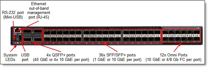
Figure 2. Front panel of the RackSwitch G8264CS
The front panel of the G8264CS contains the following components:
- LEDs that display the status of the switch and the network.
- One Mini-USB RS-232 console port that provides an additional means to configure the switch.
- One USB port for mass storage devices.
- 36x SFP/SFP+ port connectors to attach SFP/SFP+ transceivers for 1 Gb or 10 Gb Ethernet connections or DAC cables for 10 Gb Ethernet connections.
- 12x Omni Ports to attach SFP+ transceivers for 4/8 Gb Fibre Channel or 10 Gb Ethernet connections or DAC cables for 10 Gb Ethernet connections.
- 4x QSFP+ port connectors to attach QSFP+ transceivers for 40 Gb Ethernet connections or DAC cables for 40 Gb or 4x 10 Gb Ethernet connections.
- One RJ-45 10/100/1000 Mb Ethernet port for out-of-band management.
- An Ethernet link OK LED and an Ethernet Tx/Rx LED for each Ethernet port on the switch.
Figure 3 shows the rear panel of the RackSwitch G8264CS.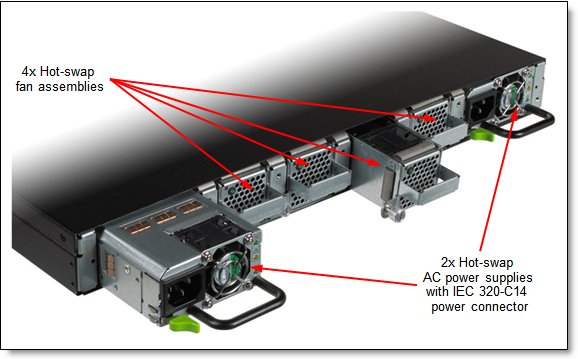
Figure 3. Rear panel of the RackSwitch G8264CS
The rear panel of the G8264CS contains the following components:
- Two hot-swap AC power supplies (IEC 320-C14 power connector)
- Four hot-swap fan assemblies
Network cabling requirements
The network cables that can be used with the switch are listed in Table 4.
Table 4. G8264CS network cabling requirements
| Transceiver | Standard | Cable | Connector |
| 40 Gb Ethernet | |||
| 40GBASE-SR QSFP+ Transceiver (49Y7884) | 40GBASE-SR4 | 10 m or 30 m MTP fiber optics cables supplied by Lenovo (see Table 3); support for up to 100 m with OM3 multimode fiber or up to 150 m with OM4 multimode fiber | MTP |
| QSFP+ 40GBASE-LR4 Transceiver (00D6222) | 40GBASE-LR4 | 1310 nm single-mode fiber cable up to 10 km | LC |
| Direct attach cable | 40GBASE-CR4 | QSFP+ to QSFP+ DAC cables up to 7 m; QSFP+ to 4x SFP+ DAC break-out cables up to 5 m for 4x 10 GbE SFP+ connections out of a 40 GbE port (see Table 3) | QSFP+ |
| 10 Gb Ethernet | |||
| SR SFP+ Transceiver (46C3447) | 10GBASE-SR | Up to 30 m with fiber cables supplied by Lenovo (see Table 3); 850 nm OM3 multimode fiber up to 300 m or up to 400 m with OM4 multimode fiber | LC |
| LR SFP+ Transceiver (00D6180) | 10GBASE-LR | 1310 nm single-mode fiber cable up to 10 km | LC |
| ER SFP+ Transceiver (90Y9415) | 10GBASE-ER | 1310 nm single-mode fiber cable up to 40 km | LC |
| Direct attach cable | 10GSFP+Cu | SFP+ DAC cables up to 7 m (see Table 3) | SFP+ |
| 1 Gb Ethernet | |||
| SFP RJ-45 Transceiver (00FE333) | 1000BASE-T | UTP Category 5, 5E, and 6 up to 100 meters | RJ-45 |
| SFP SX Transceiver (81Y1622) | 1000BASE-SX | Up 30 m with fiber optic cables supplied by Lenovo (see Table 3); 850 nm multimode fiber cable up to 550 m (50 µ) or up to 220 m (62.5 µ) | LC |
| SFP LX Transceiver (90Y9424) | 1000BASE-LX | 1310 nm single-mode fiber cable up to 10 km | LC |
| 8 Gb Fibre Channel (operating at 8 Gbps or 4 Gbps) | |||
| 8Gb SFP+ SW Optical Transceiver (44X1964) | FC-PI-4 (8GFC, 4GFC) | Up to 30 m with fiber optic cables supplied by Lenovo (see Table 3); 850 nm multimode fiber, 50 µ (up to 150 m at 8 Gbps; up to 380 m at 4 Gbps) or 62.5 µ (up to 21 m at 8 Gbps; up to 70 m at 4 Gbps) | LC |
| 8Gb SFP+ LW Optical Transceiver (00FM472) | FC-PI-4 (8GFC, 4GFC) | 1310 nm single-mode fiber cable up to 10 km (at 8 Gbps or 4 Gbps) | LC |
| Management ports | |||
| 1 GbE management port | 1000BASE-T | UTP Category 5, 5E, and 6 up to 100 meters | RJ-45 |
| RS-232 management port | RS-232 | DB-9-to-mini-USB or RJ-45-to-mini-USB console cable (comes standard with the switch) | Mini-USB |
Warranty
The RackSwitch G8264CS comes with a standard 3-year hardware warranty with Next Business Day (NBD), 9x5, Customer Replaceable Unit (CRU) warranty service from Lenovo. Software Upgrade Entitlement is based on the switch’s warranty or post warranty extension and service contracts. Optional warranty and maintenance upgrades are available for the G8264CS switch through Lenovo Services:
- Warranty service upgrades (3, 4, or 5 years)
- 24x7 onsite repair with 2-hour target response time
- 24x7 onsite repair with 4-hour target response time
- 9x5 onsite repair with 4-hour target response time
- Maintenance (post-warranty) service offerings (1 or 2 years)
- 24x7 onsite repair with 2-hour target response time
- 24x7 onsite repair with 4-hour target response time
- 9x5 onsite repair with 4-hour target response time
- 9x5 onsite repair with next business day target response time
Lenovo warranty service upgrade offerings are region-specific, that is, each region might have its own service types, service levels, response times, and terms and conditions. Not all covered types of warranty service offerings might be available in a particular region.
For more information about the Lenovo warranty service upgrade offerings that are available in your region, visit the Product Selector at the following website:
https://www-304.ibm.com/sales/gss/download/spst/servicepac
Physical specifications
The approximate dimensions and weight of the G8264CS switch are as follows:
- Height: 44 mm (1.7 in.)
- Width: 439 mm (17.3 in.)
- Depth: 483 mm (19.0 in.)
- Weight: 10.0 kg (22.0 lb)
Operating environment
The G8264CS switch is supported in the following operating environment:
- Temperature: 0 to 40 °C (32 to 104 °F).
- Relative humidity: Non-condensing, 10 - 90%
- Altitude: up to 1,800 m (6,000 feet)
- Acoustic noise: Less than 65 dB
- Airflow: Front-to-rear or rear-to-front cooling with redundant variable speed fans for reduced power draw
- Electrical input: 50-60 Hz, 100-240 V AC auto-switching
- Typical power: 330 W
Agency approvals
The switch conforms to the following regulations:
- Safety Certifications and Standards
- UL60950-1
- CAN/CSA 22.2 No.60950-1
- TUV GS to EN 60950-1
- IEC60950-1, all country deviations
- CNS 14336-1
- Argentina Smark to IEC60950-1
- GB 4943.1-2011
- GOST R MEK 60950-1-2005
- NOM-019
- Electromagnetic Compatibility Certifications
- FCC 47CFR Part 15 Class A
- EN 55022 Class A
- ICES-003 Class A
- VCCI Class A
- AS/NZS CISPR 22 Class A
- CISPR 22 Class A
- EN 55024
- KC Class A
- CE
- Environmental
- Reduction of Hazardous Substances (ROHS) 6
Typical configurations
The following configurations are expected to be among the popular configurations that clients are likely to implement. Not all of these configurations are available at the time of writing. For more information, speak to a Lenovo sales representative or Lenovo Business Partner. For examples of official tested configurations, see the System Storage Interoperation Center (SSIC) at the following website:
http://ibm.com/systems/support/storage/ssic/interoperability.wss
Lenovo provides extensive FCoE testing to deliver network interoperability. For a full listing of supported FCoE and iSCSI configurations, visit the System Storage Interoperation Center (SSIC) at the following website:
http://ibm.com/systems/support/storage/ssic
Leveraging an existing LAN
Figure 4 shows how a client with existing SAN switches can use the G8264CS to simplify its rack environments by deploying 10 Gb Ethernet in the rack between the System x or ThinkServer® servers, and the G8264CS. The client can leverage Ethernet in the rack while breaking out the FC connections at the top of the rack, to connect to the existing SAN switches, and then on to the client's storage devices.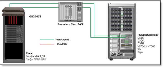
Figure 4. Leveraging an existing LAN
Table 5 lists the supported components.
Table 5. Components
| Adapter | NIC mode | FCoE switch | SAN switch | Storage target (FC) | OS levels |
| Emulex VFA II/III (Adapter + FoD Key): 49Y7950 + 49Y4274 49Y7940 + 49Y4274 95Y3751 (Included) 90Y6456 + 90Y5178 95Y3762 + 95Y3760 88Y6454 + 95Y3760 |
pNIC vNIC2 |
G8264CS | Cisco SAN Brocade SAN |
Storwize V3700 Storwize V7000 SAN Volume Controller DS3K/5K DS8K XIV Tape |
Win2008 WS2012 ESX 4/5 RHEL 5/6 SLES 10/11 |
| QLogic 8200 PCIe (Adapter + FoD Key): 90Y4600 + 00Y5624 |
pNIC vNIC2 |
G8264CS | Cisco SAN Brocade SAN |
Storwize V3700 Storwize V7000 SAN Volume Controller DS3K/5K/8K XIV Tape |
Win2008 WS2012 ESX 4/5 RHEL 5/6 SLES 10/11 |
Leveraging Ethernet further in an existing data center
Figure 5 shows an example of how a client might further simplify its data center by using Ethernet more in its data center before connecting to its existing SAN switches. This example shows how clients can use the RackSwitch G8124E to simplify its rack environments with Ethernet only. Ethernet can go down to the end of the row, or closer, to the client's storage where the client can install the G8264CS. Next, Ethernet can break out the FC connections at the top of the rack to connect to the existing SAN switches, and finally it can go on to the client's storage devices.
Figure 5. Leveraging Ethernet further in an existing data center
Table 6 summarizes the supported components.
Table 6. Components
| Adapter | NIC mode | Transit | FCoE switch | SAN switch | Storage target | OS levels |
| Emulex VFA II/III (Adapter + FoD key) 49Y7950 + 49Y4274 49Y7940 + 49Y4274 95Y3751 (Included) 90Y6456 + 90Y5178 95Y3762 + 95Y3760 88Y7429 + 95Y3760 |
pNIC vNIC2 |
G8124E | G8264CS | Cisco SAN Brocade SAN |
Storwize V3700 Storwize V7000 SAN Volume Controller DS3K/5K DS8K XIV Tape |
Win2008 WS2012 ESX 4/5 RHEL 5/6 SLES 10/11 |
| QLogic 8200 PCIe (Adapter + FoD Key) 90Y4600 + 00Y5624 |
pNIC vNIC2 |
G8124E | G8264CS | Cisco SAN Brocade SAN |
Storwize V3700 Storwize V7000 SAN Volume Controller DS3K/5K DS8K XIV Tape |
Win2008 WS2012 ESX 4/5 RHEL 5/6 SLES 10/11 |
Leveraging FCoE end to end in an existing data center
Figure 6 shows an example of how a client might further simplify their data center with the FC SAN switching fabric and implementing end to end FCoE configuration. This example shows how clients can use the RackSwitch G8264 to simplify their rack environments with Ethernet only. Ethernet can go down to the end of the row, or closer, to the client's storage where the client can install the G8264CS to connect directly upstream to an Storwize V3700/V7000 using simpler Ethernet connectivity.
Figure 6. Leveraging Ethernet further in an existing data center with end to end FCoE
Table 7 summarizes the supported components.
Table 7. Components
| Adapter | NIC mode | Transit | FCoE switch | SAN switch | Storage target | OS levels |
| Emulex VFA II/III (Adapter + FoD Key) 49Y7950 + 49Y4274 49Y7940 + 49Y4274 95Y3751 (Included) 90Y6456 + 90Y5178 95Y3762 + 95Y3760 88Y6454 + 95Y3760 |
pNIC vNIC1 |
G8264 | G8264CS FCF Mode | None | Storwize V3700 Storwize V7000 SAN Volume Controller |
WS2012 ESX 5, RHEL 6 SLES 11 |
Leveraging a BladeCenter environment
Figure 7 shows an example of how a client can use a BladeCenter environment. The client reduces costs inside the chassis with a single adapter in the blade, with a 10 Gb Ethernet adapter only in the chassis. The client can use the G8264CS at the top of the rack or somewhere else in the data center, breaking out the FC connections and connecting to the existing SAN switches, and then to the storage devices.
Figure 7. Leveraging a BladeCenter environment
Table 8 summarizes the supported components.
Table 8. Components
| Adapter | NIC mode | FCoE switch | SAN switch | Storage target | OS levels |
| Emulex VFA 2 (Adapter + FoD Key) |
pNIC vNIC2 |
G8264CS | Cisco SAN Brocade SAN |
Storwize V3700 Storwize V7000 SAN Volume Controller DS3K/5K DS8K XIV Tape |
Win2008 WS2012 ESX 4/5 RHEL 5/6 SLES 10/11 |
Leveraging a Flex System environment: NPIV to FC SAN
Figure 8 shows an example of how a client can use the G8264CS for convergence in a Flex System environment. This approach can help a client significantly reduces costs inside the chassis with a single adapter in the compute node using CNA functionality, with a 10Gb Ethernet module, such as the SI4093/EN4093/EN4093R, in the chassis (no FC adapter or switches necessary). The client can then use the G8264CS at the top of the rack or somewhere else in the data center, breaking out the FC connections and connecting to the existing Brocade or Cisco SAN switches, and then in to the storage devices.
Figure 8. Leveraging G8264CS in a Flex System environment
Table 9 summarizes the supported components.
Table 9. Components
| Adapter | NIC mode | Transit | FCoE switch | SAN switch | Storage target | OS levels |
| LOM & CN4054 4-port adapter (BE3) | pNIC, vNIC1, vNIC2, or UFP | SI4093 EN4093 EN4093R |
G8264CS NPIV mode | Brocade or Cisco SAN | Storwize V3700 Storwize V7000 SVC DS3K/5K DS8K XIV Tape |
Win2008, WS2012, W@ 2012 HyperV + NPIV, ESX 4/5/5.1/5.5, VMware ESX 5.1/5.5 + NPIV |
| CN4058 -8-port adapter | pNIC | RHEL 5/6/7, SLES 10/11 RHEL 5/6/7, SLES 11/12, AIX6/7, VIOS 221/222, IBM I6/7 VIOS |
Leveraging a Flex System environment: FCoE end-to-end
Figure 9 shows an example of how a client can use the G8264CS for convergence in a Flex System environment to connect directly into their storage using FCoE. This approach can help clients significantly reduce costs inside the chassis by removing the need for FC SAN switches between the G8264CS and the storage. In the chassis, you simply have a single adapter in the compute node using CNA functionality, with a 10Gb Ethernet module, such as the SI4093/EN4093/EN4093R, in the chassis (no FC adapter or switches necessary). The client can then use the G8264CS at the top of the rack or elsewhere in the data center and then connect directly into the storage device.
Note: FLOGI is used to obtain a routable FCID for use in the FC frame exchange between the G8264CS and the Storwize V7000. The switch provides the FCID during a FLOGI exchange.
Figure 9. Leveraging G8264CS for end to end FCoE in a Flex System environment
Table 10 summarizes the supported components.
Table 10. Components
| Adapter | NIC mode | Transit | FCoE switch | SAN switch | Storage target | OS levels |
| LOM & CN4054 4-port adapter (BE3) | pNIC, vNIC1 | SI4093 EN4093 EN4093R |
G8264CS FCF mode | None | Storwize V3700 Storwize V7000 SAN Volume Controller |
WS2008, WS2012, WS2012 HyperV + NPIV, ESX 4/5/5.1/5.5, VMware ESX 5.1/5.5 + NPIV, RHEL 5/6, SLES 10/11 |
| CN4058 8-port adapter | pNIC | RHEL 5/6/7, SLES 11/12, AIX6/7, VIOS 221/222 |
Build 252-node POD/cluster with Flex System Interconnect Fabric
With the growth of cloud, media applications, mobile connections and big data clients, IT departments are faced with many new requirements. Flex System Interconnect Fabric is designed to meet client needs by providing a simple Ethernet fabric cluster that accelerates deployment, simplifies management, and enables dynamic scalability, increases reliability, availability and security in medium to large scale POD deployments. This solution offers a solid foundation of compute, network, storage, and software resources in a Flex System POD.
The key I/O components of this solution consist of a pair of RackSwitch G8264CS. One of the G8264CS will be the center of intelligence and provides all direction and updates to the redundant G8264CS and the 2-18 Flex System SI4093 System Interconnect Modules. By using Flex System x222 compute nodes, clients can easily setup a single chassis and then scale up to nine chassis with easy to build a 252-node POD or cluster. In addition, the automated capabilities of adding additional chassis after initial setup of the first client can also exploit the acquisition and operation cost savings of converging Ethernet and Fibre Channel traffic within the POD or cluster, but still be able to simply connect into their existing upstream networks.
Figure 10 shows the Flex System Interconnect Fabric using 9 chassis with SI4093, and a pair of RackSwitch G8264CS connecting to a clients existing LAN and SAN which could be a Brocade switch or a Cisco MDS switch.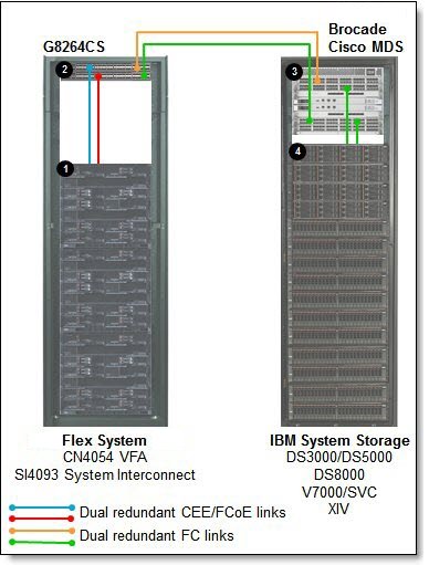
Figure 10. Flex System Interconnect Fabric using 9 chassis
The solution components that are used in the scenarios that are shown in Figure 10 are listed in Table 11.
Table 11. Building a Flex System Interconnect Fabric POD using FCoE (Figure 10)
| Diagram reference number | Description - part number - quantity |
| 1 | RackSwitch G8264CS - 7309DRX - 2 per POD
|
| 2 | Flex System chassis – supports 1-9 chassis:
|
| 3 | Independent of upstream LAN connect to your existing network vendor of choice |
| 4 | Brocade or Cisco MDS SAN fabric |
The IBM System Storage FC disk controllers can be selected from:
- DS3000 / DS5000
- DS8000
- Storwize V7000 / SAN Volume Controller
- XIV
Related product families
Product families related to this document are the following:
Trademarks
Lenovo and the Lenovo logo are trademarks or registered trademarks of Lenovo in the United States, other countries, or both. A current list of Lenovo trademarks is available on the Web at https://www.lenovo.com/us/en/legal/copytrade/.
The following terms are trademarks of Lenovo in the United States, other countries, or both:
Lenovo®
BladeCenter®
Flex System
Intelligent Cluster
Lenovo Services
NMotion®
NeXtScale
NeXtScale System®
Omni Ports
RackSwitch
System x®
ThinkServer®
VMready®
iDataPlex®
The following terms are trademarks of other companies:
Microsoft® and Hyper-V® are trademarks of Microsoft Corporation in the United States, other countries, or both.
Other company, product, or service names may be trademarks or service marks of others.


