

Top
Abstract
The Cisco Catalyst Switch Module 3110G and 3110X are Gigabit Ethernet Switch Modules in a standard switch-bay form-factor for use in all BladeCenter chassis. These stackable switches are full wire-rated, non-blocking switches for use with high performance servers.
Introduction
The Cisco Catalyst Switch Module 3110G and 3110X are Gigabit Ethernet Switch Modules in a standard switch-bay form-factor for use in all BladeCenter chassis. These stackable switches are full wire-rated, non-blocking switches for use with high performance servers. The 3110G offers four external RJ-45 Gigabit Ethernet connections and the 3110X offers one external 10 Gb Ethernet slot (for use with an X2 transceiver module) for making 10Gb uplinks to backbone switches or routers.
Built upon Cisco's market-leading hardware and IOS software, the switches are designed to deliver scalable, high performance, highly resilient connectivity while reducing server infrastructure complexity.
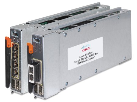
Figure 1. Cisco Catalyst Switch Module 3110G (left) and 3110X (right). The 3110X is shown with an optional X2 transceiver module installed.
Did you know?
The Cisco Catalyst Switch Module 3110 has a unique technology called Virtual Blade Switch (VBS). Much like server virtualization technology, this switch virtualization technology treats the individual physical switches within a rack as a single logical switch. As with server virtualization technology, this innovation allows the switches to deliver better utilization, increased performance, and greater resilience while simplifying operations and management.
Part number information
Table 1. Part numbers and feature codes for ordering
| Description | IBM part number | Feature code | Cisco part number |
| Cisco Catalyst Switch Module 3110G | 41Y8523 | 2989 | None |
| Cisco Catalyst Switch Module 3110X | 41Y8522 | 2988 | None |
| IP Services S/W Upgrade License for Catalyst 3110 | 43W4434 | 4901 | 3110-IPS-LIC-I |
| Advanced IP Services S/W Upgrade License for Cisco Catalyst 3110 | None | None | 3110-AISK9-LIC-I |
The Cisco Catalyst Switch Modules 3110G and 3110X come standard with IP Base feature set software. Additional features require licenses, as listed in Table 1:
- The IP Services S/W Upgrade License provides support for advanced routing protocols, including EIGRP, OSPF, BGP, and PIM. It can be ordered through standard IBM sales channels or from a Cisco Systems reseller.
- The Advanced IP Services S/W Upgrade License provides support for IPv6 forwarding and routing. It is available through a Cisco Systems reseller only.
The switch module part numbers include the following items:
- Cisco Catalyst Switch Module 3110G or Cisco Catalyst Switch Module 3110X
- USB-to-DB9 console cable
- One 1-meter StackWise Plus cable
- Documentation
The switches each have two external high-speed StackWise Plus ports for switch module stacking to support Virtual Blade Switch technology. Each 3110G and 3110X switch module ships with one 1-meter StackWise Plus cable. Other cable lengths are available as listed in Table 2.
Table 2. StackWise Plus cables
| Description | Cisco part number |
| 0.5 meter cable | CAB-STK-E-0.5M= |
| 1 meter cable (one is included with the switch) | CAB-STK-E-1M= |
| 3 meter cable | CAB-STK-E-3M= |
The Cisco Catalyst Switch Module 3110X requires a transceiver for the 10Gb Ethernet Module slot. Transceiver modules are not included and can be ordered from a Cisco Systems reseller. Certain transceivers can also be ordered directly from IBM.
The available transceiver modules are listed in Table 3.
Table 3. Transceivers for the Cisco Catalyst Switch Module 3110X
| Description | IBM part number | Cisco part number |
| Cisco 10GBASE-SR SFP+ Transceiver | 88Y6054 | SFP-10G-SR(=) |
| Cisco 1000BASE-T SFP Transceiver | 88Y6058 | GLC-T(=) |
| Cisco 1000BASE-SX SFP Transceiver (GE SFP, LC connector) | 88Y6062 | GLC-SX-MM(=) |
| Cisco OneX Converter Module X2 transceiver module (supports 1 SFP module) | 88Y6066 | CVR-X2-SFP10G= |
| 10GBASE-CX4 X2 transceiver module for CX4 cable, copper, InfiniBand 4X connector | Not available | X2-10GB-CX4= |
| 10GBASE-SR X2 transceiver module for MMF, 850-nm wavelength, SC duplex connector | Not available | X2-10GB-SR= |
| 10GBASE-LRM X2 transceiver module for MMF, 1310-nm wavelength, SC duplex connector | Not available | X2-10GB-LRM= |
| Cisco TwinGig X2 Converter Module | Not available | CVR-X2-SFP= |
The Cisco 10GBASE-SR SFP+ Transceiver (88Y6054) supports a link length of 26 meters on standard Fiber Distributed Data Interface (FDDI)-grade multimode fiber (MMF).
The Cisco 1000BASE-T SFP Transceiver (88Y6058) operates on standard Category 5 unshielded twisted pair copper cabling of up to 100 meters (328 ft) link length. Cisco 1000BASE-T SFP modules support 10/100/1000 autonegotiation and Auto MDI/MDIX.
The Cisco 1000BASE-SX SFP Transceiver (88Y6062) is compatible with the IEEE 802.3z 1000BASE-SX standard and operates on 50 µm multimode fiber links up to 550 m and on 62.5 µm Fiber Distributed Data Interface (FDDI)-grade multimode fibers up to 220 m. It can support up to 1km over laser-optimized 50 µm multimode fiber cable.
The Cisco OneX Converter Module (88Y6066) offers investment protection for Cisco 3110X users by enabling migration from X2 to Small Form-Factor Pluggable Plus (SFP+) form factor without having to upgrade the switches or modules. You can install one SFP module in this converter module - 88Y6054, 88Y6058, or 88Y6062 as listed in Table 3.
Features
The supported features and specifications for the Cisco Catalyst Switch Modules 3110G and 3110X are:
- Ports
- 3110G: Four external RJ-45 1000BASE-T connectors for making 10/100/1000 Mbps connections to a backbone, end stations, and servers.
- 3110X: One external 10 Gb Ethernet Module slot for forming 10Gb uplinks to backbone switches or routers. This module slot operates at full-duplex and uses hot-swappable Cisco X2 transceiver modules. The transceiver module is not included and must be ordered from a Cisco Systems reseller as listed in Table 3.
- Two external high-speed StackWise Plus ports for switch module stacking to support Virtual Blade Switch (VBS) technology. Each 3110G switch module ships with one 1-meter StackWise Plus cable. Other cables are available for order from Cisco Systems resellers as listed in Table 2.
- USB-style serial port. This is the Cisco console port, and offers an out-of-band management path if desired. A USB-to-DB-9 cable is used to connect the switch module to a PC. This cable is shipped with the switch.
- 14 internal full-duplex Gigabit ports, one connected to each of the blade servers in the BladeCenter unit.
- One internal full-duplex 100 Mbps port connected to the management module.
- Performance features
- 3110G: Auto-sensing of speed on the 10/100/1000 ports and auto-negotiation of duplex mode on the ports for optimizing bandwidth.
- 3110X: Fixed 10 Gbps speed on external 10 Gb Ethernet port for maximum uplink bandwidth.
- Up to 64 Gbps of throughput in a switch stack.
- Gigabit EtherChannel (3110G) or 10 Gb EtherChannel (3110X) for enhanced fault tolerance and to provide up to 8 Gbps (3110G) or 80 Gbps (3110X) of bandwidth between switches, routers, and servers.
- Support for standard frames with sizes from 64 to 1530 bytes and jumbo frames with a maximum size of 9216.
- Forwarding of Layer 2 frames and Layer 3 packets at 1 Gbps line rate across switches in stack.
- Per-port broadcast-storm control for preventing a faulty end station from degrading overall system performance with broadcast storms.
- Port Aggregation Protocol (PAgP) and Link Aggregation Control Protocol (LACP) for automatic creation of EtherChannel links.
- Internet Group Management Protocol (IGMP) snooping support to limit flooding of IP multicast traffic.
- Multicast Virtual Local Area Network (VLAN) registration (MVR) to continuously send multicast streams in a multicast VLAN while isolating the streams from subscriber VLANs for bandwidth and security.
- IGMP filtering for controlling the set of multicast groups to which hosts on a switch port can belong.
- Dynamic address learning for enhanced security.
- Support for multiple EtherChannel load balance algorithms (SMAC or DMAC, SIP or DIP, XOR-SMAC/DMAC or XOR-SIP/DIP) to offer maximum performance on aggregated links.
- Web Cache Communication Protocol (WCCP) for redirecting traffic to wide area application engines, for enabling content requests to be fulfilled locally, and for localizing Web traffic patterns in the network (supported by IP Services feature set only).
- Manageability
- Address Resolution Protocol (ARP) for identifying a switch through its IP address and its corresponding MAC address.
- Cisco Discovery Protocol (CDP) Versions 1 and 2 to aid in troubleshooting and reporting on misconfiguration of ports connecting to other devices supporting CDP.
- Link Layer Discovery Protocol (LLDP) and LLDP Media Endpoint Discovery (LLDP-MED) for interoperability with third-party IP phones.
- Network Time Protocol (NTP) for providing a consistent time stamp to all switches from an external source.
- Directed unicast requests to a Trivial File Transfer Protocol (TFTP) server for obtaining software upgrades from a TFTP server.
- Default configuration storage in flash memory to ensure that the switch can be connected to a network and can forward traffic with minimal user intervention.
- In-band monitoring of the switch through the built-in Cisco Device Manager Web-based tool.
- In-band management access through up to 16 simultaneous Telnet connections for multiple command line interface (CLI)-based sessions over the network.
- In-band management access through up to five simultaneous, encrypted Secure Shell (SSH) connections for multiple CLI-based sessions over the network. This option is available only in the cryptographic software image.
- In-band management access through SNMP versions 1, 2c, and 3 get and set requests.
- Out-of-band management (CLI) with switch module’s console port.
- Supported by CiscoWorks management software.
- Protected Mode feature to isolate switch management from Advanced Management Module, for increased security of the switch.
- Cisco Network Services (CNS) embedded agents for automating switch management, configuration store, and delivery.
- Cisco Network Assistance (CNA), a free GUI-based application tool to configure most features of this switch. For more information and download of CNA, go to http://www.cisco.com/go/cna
- Extensive debugging options to aid in troubleshooting and diagnosing issues.
- Support for multiple management interfaces.
- Availability and redundancy
- Hot Standby Routing Protocol (HSRP) for Layer 3 router redundancy.
- Automatic stack master failover for replacing failed stack masters.
- Cross-stack EtherChannel for providing redundant links across switch stack.
- Link state tracking to mirror the state of the external ports on the internal Ethernet links and to allow the failover of the processor blade traffic to an operational external link on a separate Cisco Ethernet switch.
- Configurable Unidirectional link detection (UDLD) for detecting and disabling unidirectional links. This feature prevents a larger network failure in the event that a unidirectional link is detected, thus reducing downtime in these situations.
- IEEE 802.1D Spanning Tree Protocol (STP) for redundant backbone connections and loop-free networks.
- IEEE 802.1s Multiple STP (MSTP) for grouping VLANs into a spanning-tree instance, and provided for multiple forwarding paths for data traffic and load balancing.
- IEEE 802.1w Rapid STP (RSTP) for rapid convergence of the spanning tree by immediately transitioning root and designated ports to the converting state.
- Optional spanning-tree features available in the PVST+, rapid PVST+, and MSTP modes.
- Flex Link Layer 2 interfaces to back up one another as an alternative to STP for basic link redundancy.
- VLAN support
- Support for 1005 total VLANs. These VLANs can be any VLAN ID from 1–4094, except 1001–1005, which are reserved by Cisco.
- Cisco Inter-Switch Link (ISL) and IEEE 802.1Q trunking protocol on all ports for network moves, adds, and changes; management and control of broadcast and multicast traffic; and network security by establishing VLAN groups for high-security users and network resources.
- VLAN Query Protocol (VQP) for dynamic VLAN membership.
- VLAN Trunking Protocol (VTP) pruning for reducing network traffic by restricting flooded traffic to links destined for stations receiving the traffic.
- Dynamic Trunking Protocol (DTP) for negotiating trunking on a link between two devices and for negotiating the type of trunking encapsulation (802.1Q) to be used.
- Voice VLAN for creating subnets for voice traffic from Cisco IP phones.
- VLAN 1 minimization to reduce the risk of spanning-tree loops or storms by enabling VLAN 1 to be disabled on any individual VLAN trunk link. With this feature enabled, no user traffic is sent or received. The switch CPU continues to send and receive control protocol frames.
- Private VLANs to address VLAN scalability issues.
- VLAN Flex Link Load Balancing to provide Layer 2 link redundancy without STP.
- Support for up to 128 instances of spanning tree per switch or per switch stack.
- Security
- Bridge protocol data unit (BPDU) guard for shutting down a Port Fast-configured port when an invalid configuration occurs.
- Protected port option for restricting the forwarding of traffic to designated ports on the same switch.
- Password-protected access (read-only and write-only access) to management interfaces (the device manager and CLI) for protection against unauthorized configuration changes.
- Port security option for limiting and identifying MAC addresses of the station allowed to access the port.
- Port security aging to set the aging time for secure addresses on a port.
- Multilevel security for a choice of security level, notification, and resulting actions.
- MAC-based port-level security for restricting the use of a switch port to a specific group of source addresses and preventing switch access from unauthorized stations.
- MAC-based access control lists (ACLs).
- Standard and extended IP access control lists (ACLs) for defining security policies on Layer 3 (router ACLs) and Layer 2 (port ACLs) interfaces.
- Terminal Access Controller Access Control System Plus (TACACS+), a proprietary feature for managing network security through a TACACS server.
- RADIUS for verifying the identity of, granting access to, and tracking activities of remote users.
- IEEE 802.1X port-based authentication to prevent unauthorized devices from gaining access to the network.
- IEEE 802.1X port-based authentication with VLAN assignment for restricting 802.1X-authenticated users to a specified VLAN.
- IEEE 802.1X port-based authentication with port security for authenticating the port and managing network access for all MAC addresses, including that of the client.
- IEEE 802.1X port-based authentication with voice VLAN to allow an IP phone access to the voice VLAN irrespective of the authorized or unauthorized state of the port.
- IEEE 802.1X port-based authentication with guest VLAN to provided limited services to non-802.1X-compliant users.
- IEEE 802.1X accounting to track network usage.
- Quality of Service (QoS) and Class of Service (CoS)
- Automatic QoS (auto-QoS) to simplify the deployment of existing QoS features by classifying traffic and configuring egress queues.
- Cross-stack QoS for configuring QoS features to all switches in a switch stack rather than on an individual-switch basis.
- Classification
- IP Type of Service/Differentiated Services Code Point (IP ToS/DSCP) and IEEE 802.1p CoS marking priorities on a per-port basis for protecting the performance of mission-critical applications.
- IP ToS/DSCP and IEEE 802.1p CoS marking for flow-based packet classification (classification based on information in the MAC, IP, and TCP/UDP headers) for high-performance QoS at the network edge, allowing for differentiated service levels for different types of network traffic and prioritizing mission-critical traffic in the network.
- Trusted port states (CoS, DSCP, and IP precedence) within a QoS domain and with a port bordering another QoS domain.
- Trusted boundary for detecting the presence of a Cisco IP Phone, trusting the CoS value received, and ensuring port security.
- Policing
- Traffic-shaping policies on the switch port for managing how much of the port bandwidth should be allocated to a specific traffic flow.
- Out-of-profile markdown for packets that exceed bandwidth utilization limits.
- Ingress queuing and scheduling
- Two configurable ingress queues for user traffic (one queue can be the priority queue).
- Weighted tail drop (WTD) as the congestion-avoidance mechanism for managing the queue lengths and providing drop precedences for different traffic classifications.
- Shaped round robin (SRR) as the scheduling service for specifying the rate at which packets are sent to the stack or internal ring (sharing is the only supported mode on ingress queues).
- Egress queues and scheduling
- Four egress queues per port.
- WTD as the congestion-avoidance mechanism for managing the queue lengths and providing drop precedences for different traffic classifications.
- SRR as the scheduling service for specifying the rate at which packets are dequeued to the egress interface (shaping or sharing is supported on egress queues).
- Automatic quality of service (QoS) voice over IP (VoIP) enhancement for port-based trust of DSCP and priority queuing for egress traffic.
- Egress policing and scheduling of egress queues - four egress queues on all switch ports; support for strict priority and weighted round-robin (WRR) CoS policies.
- Layer 3 features
- HSRP for Layer 3 router redundancy.
- IP routing protocols for load balancing and for constructing scalable, routed backbones:
- RIP Versions 1 and 2.
- OSPF (IP services feature set is required).
- Enhanced IGRP (EIGRP) (IP services feature set is required).
- Border Gateway Protocol (BGP) Version 4 (IP services feature set is required).
- IP routing between VLANs (inter-VLAN routing) for full Layer 3 routing between two or more VLANs, allowing each VLAN to maintain its own autonomous data-link domain.
- Policy-based routing (PBR) for configuring defined policies for traffic flows (IP services feature set is required).
- VPNs (IP services feature set is required).
- Fallback bridging for forwarding non-IP traffic between two or more VLANs (IP services feature set is required).
- Static IP routing for manually building a routing table of network path information.
- Equal-cost routing for load-balancing and redundancy.
- Internet Control Message Protocol (ICMP) and ICMP Router Discovery Protocol (IRDP) for using router advertisement and router solicitation messages to discover the addresses of routers on directly-attached subnets.
- Protocol-Independent Multicast (PIM) for multicast routing within the network, allowing for devices in the network to receive the multicast feed requested and for switches not participating in the multicast to be pruned. Includes support for PIM sparse mode (PIM-SM), PIM dense mode (PIM-DM), and PIM sparse-dense mode (IP services feature set is required).
- Multicast Source Discovery Protocol (MSDP) for connecting multiple PIM-SM domains (IP services feature set is required).
- Distance Vector Multicast Routing Protocol (DVMRP) tunneling for interconnecting two multicast-enabled networks across nonmulticast networks (an IP services feature set is required).
- DHCP relay for forwarding UDP broadcasts, including IP address requests, from DHCP clients.
- IPv6 support:
- IPv6 host support (IPv6 unicast addressing, IPv6 traffic processing, IPv6 applications support including DNS, ping, traceroute, telnet, ftp, tftp, http, and ssh). IPv6 traffic forwarding is not supported. IPv6 host support is incorporated into an IP Base software feature set that comes standard with this switch module.
- IPv4 and IPv6 coexistence. The switch module supports dual IPv4 and IPv6 protocol stacks to provide seamless step-by-step migration to an IPv6 environment.
- IPv6 unicast routing capability (IPv6 traffic forwarding, static routes, RIP, and OSPF) for forwarding IPv6 traffic through configured interfaces (an advanced IP services feature set is required).
- Support for EIGRP IPv6, which utilizes IPv6 transport, communicates with IPv6 peers, and advertises IPv6 routes (an advanced IP services feature set is required).
- Support for IPv6 Access Control Lists (ACLs) (an advanced IP services feature set is required).
- IP unicast reverse path forwarding (unicast RPF) for confirming source packet IP addresses.
- Nonstop forwarding (NSF) awareness to enable the Layer 3 switch to continue forwarding packets from an NSF-capable neighboring router when the primary route processor (RP) is failing and the backup RP is taking over, or when the primary RP is manually reloaded for a nondisruptive software upgrade (an IP services feature set is required).
- NSF-capable routing for OSPF and EIGRP that allows the switch to rebuild routing tables based on information from NSF-aware and NSF-capable neighbors (an IP services feature set is required).
- Monitoring
- Switch LEDs that provide visual port, switch, and stack-level status.
- SPAN/RSPAN support for local and remote monitoring of the network.
- Four groups (history, statistics, alarms, and events) of embedded remote monitoring (RMON) agents for network monitoring and traffic analysis.
- MAC address notification for tracking the MAC addresses that the switch has learned or removed.
- Syslog facility for logging system messages about authentication or authorization errors, resource issues, and time-out events.
- Layer 2 trace route to identify the physical path that a packet takes from a source device to a destination device.
- Time Domain Reflector (TDR) to diagnose and resolve cabling problems on 10/100 and 10/100/1000 copper Ethernet ports.
- Online diagnostics to test the hardware functionality of the supervisor engine, modules, and switch while the switch is connected to a live network.
- On-board failure logging (OBFL) to collect information about the switch and the power supplies connected to it.
- Enhanced object tracking (EOT) for HSRP to determine the proportion of hosts in a LAN by tracking the routing table state or to trigger the standby router failover.
- IP Service Level Agreements (IP SLAs) support to measure network performance by using active traffic monitoring (IP services feature set is required).
- IEEE standards
The Cisco Catalyst Switch Modules 3110G and 3110X support the following IEEE standards:
- IEEE 802.1d Spanning Tree Protocol (STP)
- IEEE 802.1s Multiple STP (MSTP)
- IEEE 802.1w Rapid STP (RSTP)
- IEEE 802.1p CoS prioritization
- IEEE 802.1Q Tagged VLAN (frame tagging on all ports when VLANs are enabled)
- IEEE 802.1x port-based authentication
- IEEE 802.2 Logical Link Control
- IEEE 802.3 10BASE-T Ethernet
- IEEE 802.3u 100BASE-TX Fast Ethernet
- IEEE 802.3ab 1000BASE-T Gigabit Ethernet
- IEEE 802.3z 1000BASE-X
- IEEE 802.3ad Link Aggregation Control Protocol
- IEEE 802.3x Full-duplex Flow Control on all ports
- IEEE 802.3ae 10GBASE-SR 10 Gb Ethernet (3110X only)
Virtual Blade Switch technology
Virtual Blade Switch (VBS) technology allows you to combine several physical network switches into one logical entity by using high-speed dedicated stacking ports on these switches to form a high-speed ring. This logical switch appears as a single network device to the blade servers and external network devices. The raw capacity of the ring is 64 Gbps. Actual throughput depends on traffic patterns and traffic type. A sample topology is shown in Figure 2.
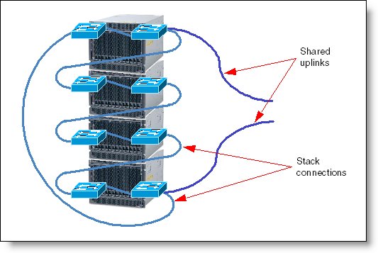
Figure 2. Virtual Blade Switch sample topology
A VBS stack has the following major characteristics:
- Up to nine physical switches can be combined in one stack: one master switch, and up to eight member switches.
- Two dedicated connectors on a switch are used to create VBS, and switches are connected in a ring. Stack connections form two counter-rotating unidirectional links, with up to 32 Gbps of raw capacity per stack member (16 Gbps per ring link).
- Single point of management.
- All switches in a stack are managed through a single IP address on the master switch.
- Single configuration file per stack.
- Single software upgrade for entire stack.
- Single Spanning Tree Protocol (STP) instance for Layer 2 networks.
- Single router for Layer 3 networks.
- Consolidation of uplink ports (or uplink sharing).
You need to take several considerations into account when planning VBS deployment:
- VBS stacking is well-suited to the concept of rack-level management, so we recommend that you build one VBS (or more VBSes, if the network paths from different server NICs must be physically separated) from the switches in the same rack whenever possible.
- In case of a master switch failure, any other member switch is eligible to become master to provide availability and redundancy.
- In case of a switch failure, the stack connections are looped back to keep the ring operational.
- True active-active NIC teaming (link aggregation of Ethernet NICs) is possible using supported link aggregation protocols like EtherChannel or 802.3ad LACP. For example, for network bandwidth-intensive applications it is possible to use up to four Ethernet ports per blade combined into a single aggregated bundle (integrated Ethernet and Ethernet ports on expansion cards).
Physically, each port is connected to a different physical switch. However, because of VBS, aggregation is done on a stack level and the blade appears to be connected to the single switch.
- Uplink sharing can help simplify design by reducing the number of external links going out of the rack; that is, not all switches in the stack must have uplinks. For example, instead of using two 1 Gb ports per switch as a redundant uplink for eight switches for a total of 16 cables going out of rack, you may choose to use just two 10 Gb links going out of the rack if applicable.
- If a fully redundant topology is required, that is, if each blade server must have two separate paths to the external infrastructure, then you can use two VBS stacks. One stack combines switches from the upper Ethernet switch bays of a chassis, and the other stack combines switches from the lower Ethernet switch bays. In this case, the entire rack will be represented as two separate network switches, both from the blade server side and from the external infrastructure side.
- Networking technologies and protocols, including VLANs, STP and its modifications (such as PVST+, RSTP, MSTP), link aggregation, link state tracking, and routing, are supported on the VBS level as well.
Note: When the switch stack is formed, the Advanced Management Module cannot manage any member of the stack (including the master switch) over IP. Management over external ports or a serial console cable is required.
Supported BladeCenter chassis and expansion cards
The Cisco Catalyst Switch Modules 3110G and 3110X are supported in the BladeCenter chassis as listed in Table 4.
Table 4. BladeCenter chassis that support the Cisco Catalyst Switch Modules 3110G and 3110X
| Cisco Catalyst Switch Module 3110G | 41Y8523 | N | Y† | Y | Y | Y | Y | N |
| Cisco Catalyst Switch Module 3110X | 41Y8522 | N | Y† | Y | Y | Y | Y | N |
† The Advanced Management Module must be installed in the BladeCenter E chassis
The Cisco Catalyst Switch Modules 3110G and 3110X support the expansion cards listed in Table 5. Table 5 also lists the chassis bays in which the switch module must be installed when used with each expansion card.
The Cisco Catalyst Switch Modules 3110G and 3110X fit in a standard I/O bay (bays 1-4) and, with the addition of the Multi-Switch Interconnect Module (MSIM) in the BladeCenter H, can also fit in a high-speed I/O bay (bays 7-10). These switch modules are not supported with MSIM-HT in high-speed bays of the BladeCenter HT chassis.
Table 5. Expansion card and BladeCenter chassis I/O bays support.
| Gigabit Ethernet integrated on the server planar | None | Y | Y‡ | N | N | N | N | N | N | N | N |
| Ethernet Expansion Card (CFFv) | 39Y9310 | Y† | Y† | Y | Y | N | N | N | N | N | N |
| Ethernet Expansion Card (CIOv) | 44W4475 | N | N | Y | Y | N | N | N | N | N | N |
| QLogic Ethernet and 4 Gb FC Card (CFFh) | 39Y9306 | N | N | N | N | N | N | Y | N | Y | N |
| 2/4 Port Ethernet Expansion Card (CFFh) | 44W4479 | N | Y* | N | N | N | N | Y | Y | Y | Y |
| QLogic Ethernet and 8 Gb FC Card (CFFh) | 44X1940 | N | N | N | N | N | N | Y | N | Y | N |
‡ For all BladeCenter chassis except the BladeCenter S
† Supported only if the expansion card is installed in slot 1 of a BladeCenter Storage and I/O Expansion Unit (39R7563).
* The 2/4 Port Ethernet Expansion Card supports I/O bay 2 connections only when installed into a blade server that is installed into a BladeCenter S chassis.
Popular configurations
This section shows how the Cisco Catalyst Switch Modules 3110G and 3110X can be used in configurations.
Basic two-port configuration
Figure 3 shows basic use of the Cisco Catalyst Switch Modules 3110 to route the two-port Ethernet controller that is integrated onto the blade server. Two Ethernet Switch Modules are installed in bay 1 and bay 2 of the BladeCenter chassis. The connections between the controller and the switch modules are internal to the chassis. The two switches are connected together with StackWise Plus cables to form a single Virtual Blade Switch.
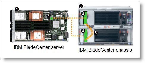
Figure 3. Using Cisco Catalyst Switch Module 3110 to route the integrated Ethernet ports
Table 6 lists the components that are used in the two-port configuration shown in Figure 3.
Table 6. Components used in the two-ports-per-server configuration
| Diagram reference | Part number / machine type | Description | Quantity |
| Varies | BladeCenter HS22 or other server | 1 to 14 | |
| None | Ethernet controller on the system board of the server | 1 per server | |
| Varies | BladeCenter E, H, HT or T | 1 | |
| 41Y8523 or 41Y8522 | Cisco Catalyst Switch Module 3110G or 3110X | 2 | |
| None | StackWise Plus cables (one included with each Cisco switch) | 2 |
Four-port configuration
Figure 4 shows the use of four Cisco Catalyst Switch Module 3110 units to route four Ethernet ports from each server: the two integrated ports plus two ports supplied by a compatible CFFv or CIOv expansion card. Four Ethernet Switch Modules are installed in bay 1, bay 2, bay 3, and bay 4 of the BladeCenter chassis. All connections between the controller and card and the switch modules are internal to the chassis. The four switches are connected together with StackWise Plus cables to form a single Virtual Blade Switch.
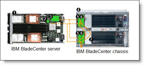
Figure 4. Using the Cisco Catalyst Switch Module 3110 to route the four Ethernet ports from the integrated controller and a CFFv or CIOv expansion card
Table 7 lists the components that are used in the four-port configuration shown in Figure 4.
Table 7. Components used in the four-ports-per-server configuration
| Diagram reference | Part number / machine type | Description | Quantity |
| Varies | BladeCenter HS22 or other supported server | 1 to 14 | |
| None | Ethernet controller on the system board of the server | 1 per server | |
| Varies | Compatible CFFv or CIOv expansion card (see Table 5) | 1 per server | |
| Varies | BladeCenter E, H, HT or T | 1 | |
| 41Y8523 or 41Y8522 | Cisco Catalyst Switch Module 3110G or 3110X routing signals from the CFFv or CIOv card |
2 | |
| 41Y8523 or 41Y8522 | Cisco Catalyst Switch Module 3110G or 3110X routing signals from the integrated controller |
2 | |
| None | StackWise Plus cables (one included with each Cisco switch) | 4 |
Maximum configuration: Eight Ethernet ports per server
Since BladeCenter servers support a CFFh expansion card plus either a CFFv or CIOv card (depending on the model of the server), you can install up to eight Cisco Catalyst Switch Module 3110 devices in a BladeCenter H chassis or BladeCenter HT. Figure 5 shows this eight-port solution. All connections between the cards and the switch modules are internal to the chassis. The eight switches are connected together with StackWise Plus cables to form a single Virtual Blade Switch.
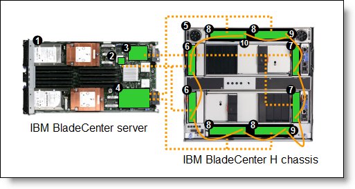
Figure 5. Using the Cisco Catalyst Switch Module 3110 to route eight Ethernet ports per server
Table 8 lists the components that are used in the eight-Ethernet-ports-per-server configuration shown in Figure 5.
Table 8. Components used in the eight-Ethernet-ports-per-server configuration
| Diagram reference | Part number / machine type | Description | Quantity |
| Varies | BladeCenter HS22 or other supported server | 1 to 14 | |
| None | Ethernet controller on the system board of the server | 1 per server | |
| Varies | Compatible CFFv or CIOv expansion card (see Table 5) | 1 per server | |
| 44W4479 | 2/4 Port Ethernet Expansion Card (CFFh) | 1 per server | |
| 8852 | BladeCenter H chassis | 1 | |
| 41Y8523 / 41Y8522 | Cisco Catalyst Switch Module 3110 routing signals from the integrated controller |
2 | |
| 41Y8523 / 41Y8522 | Cisco Catalyst Switch Module 3110 routing signals from the CFFv or CIOv card |
2 | |
| 41Y8523 / 41Y8522 | Cisco Catalyst Switch Module 3110 routing signals from the CFFh card |
4 | |
| 39Y9314 | Multi-switch Interconnect Module | 2 | |
| 10 | None | StackWise Plus cables (one included with each Cisco switch) | 8 |
Connectors and LEDs
Figure 6 shows the front panels of the Cisco Catalyst Switch Module 3110G and 3110X.

Figure 6. Front panel of the Cisco Catalyst Switch Module 3110G (left) and 3110X (right).
The front panel contains the components identified in Table 9.
Table 9. Front panel callouts
| Callout | Description |
| 1, 8 | Stack member LED |
| 2, 9 | Mode button |
| 3, 10 | Fault/stack mode LED |
| 4, 11 | System power LED |
| 5, 12 | Stack master LED |
| 6, 7 | Port link and activity LEDs for each RJ-45 (3110G) |
| 13 | X2 port status LEDs (3110X) |
Network cabling requirements
The network cables required for the switch module are as follows.
Cisco Catalyst Switch Module 3110G network cables
- 10BASE-T:
- UTP Category 3, 4, 5 (100 meters (328 feet) maximum)
- 100-ohm STP (100 meters maximum)
- 100BASE-TX:
- UTP Category 5 (100 meters maximum)
- EIA/TIA-568 100-ohm STP (100 meters maximum)
- 1000BASE-T:
- UTP Category 6
- UTP Category 5e (100 meters maximum)
- UTP Category 5 (100 meters maximum)
- EIA/TIA-568B 100-ohm STP (100 meters maximum)
Cisco Catalyst Switch Module 3110X network cables
10GBASE-SR cables are listed in Table 10.
Table 10. 10GBASE-SR cabling specifications
| Wavelength | Cable type | Core size (microns) |
Modal bandwidth (MHz/km) |
Maximum cable length |
| 850 nm | MMF | 62.5 | 160 | 85 feet (26 m) |
| 850 nm | MMF | 62.5 | 200 | 108 feet (33 m) |
| 850 nm | MMF | 50 | 400 | 217 feet (66 m) |
| 850 nm | MMF | 50 | 500 | 269 feet (82 m) |
| 850 nm | MMF | 50 | 2000 | 984 feet (300 m) |
10GBASE-LRM cables are listed in Table 11.
Table 11. 10GBASE-LRM cabling specifications
| Wavelength | Cable type | Core size (microns) |
Modal bandwidth (MHz/km) |
Maximum cable length |
| 1310 nm | MMF | 62.5 | 500 | 984 feet (300 m) |
| 1310 nm | MMF | 50 | 400 | 787 feet (240 m) |
| 1310 nm | MMF | 50 | 500 | 984 feet (300 m) |
10GBASE-CX4: The InfiniBand copper cable with 4X InfiniBand connector has a maximum cable length of 49 feet (15 m).
Operating environment
The operating environment must meet the following temperature and altitude requirements:
- Temperature: 10° to 35°C (50° to 95°F)
- Relative humidity: 8% to 80% non-condensing
Related product families
Product families related to this document are the following:
Trademarks
Lenovo and the Lenovo logo are trademarks or registered trademarks of Lenovo in the United States, other countries, or both. A current list of Lenovo trademarks is available on the Web at https://www.lenovo.com/us/en/legal/copytrade/.
The following terms are trademarks of Lenovo in the United States, other countries, or both:
Lenovo®
BladeCenter Interoperability Guide
BladeCenter®
Other company, product, or service names may be trademarks or service marks of others.


