

Top
Abstract
The IBM BladeCenter Layer 2-7 Gigabit Ethernet Switch Module serves as a switching and routing fabric for the IBM BladeCenter server chassis. It also introduces Layer 4-7 functionality for application-based and server-based load balancing, advanced filtering, content-aware intelligence, embedded security services, and persistence support. The Switch Module supplies four Gigabit Ethernet External copper ports, 14 Gigabit Ethernet internal ports and two 10/100 Ethernet management ports.
Note: This product has been withdrawn from marketing and is no longer available for ordering from IBM.
Introduction
The IBM BladeCenter Layer 2-7 Gigabit Ethernet Switch Module serves as a switching and routing fabric for the IBM BladeCenter server chassis. It also introduces Layer 4-7 functionality for application-based and server-based load balancing, advanced filtering, content-aware intelligence, embedded security services, and persistence support. The Switch Module supplies four Gigabit Ethernet External copper ports, 14 Gigabit Ethernet internal ports and two 10/100 Ethernet management ports.
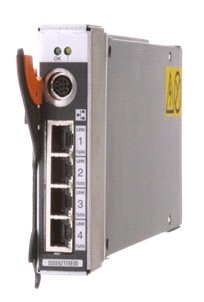
Figure 1. IBM BladeCenter Layer 2-7 Gigabit Ethernet Switch Module
Did you know?
The IBM BladeCenter Layer 2-7 Gigabit Ethernet Switch is the only blade switch in the industry to provide enhancements to the standard Layer 2 switching functions by introducing Layer 3 Routing, Layer 4 through Layer 7 Virtual Server Load Balancing, application availability, and security features consolidated into a standard form factor I/O module. It supports up to 300,000 simultaneous Layer 2 through Layer 7 sessions and full wire-speed packet forwarding for all connections. This switch is ideal for infrastructure applications requiring load balancing such as TCP/UDP, firewalls, VPN, SIP for Voice-over-IP, Microsoft Terminal Server (RDP), and IBM Enterprise Workload Manager.
Part number information
Table 1 lists the part number to order the module and supported optical transceivers.
Table 1. Part number and feature code for ordering
The part numbers include the following items:
Table 1. Part number and feature code for ordering
| Description | Part number | Feature codes |
| IBM BladeCenter Layer 2-7 Gigabit Ethernet Switch Module | 32R1859 | 1494 |
The part numbers include the following items:
- One IBM BladeCenter Layer 2-7 Gigabit Ethernet Switch Module
- DIN-to-DB9 serial console cable
- Printed documentation
- Documentation CD-ROM
Benefits
The IBM BladeCenter Layer 2-7 Gigabit Ethernet Switch Module flattens the topology of the data center infrastructure, resulting in less devices which translates into lower capital and operating expenses. The Layer 2-7 Gigabit Ethernet Switch Module offers the following benefits:
- Enables consolidation of full Layer 2-7 LAN switching capabilities into IBM BladeCenter
- Supports virtualized network services using VLANs, Virtual IPs, Virtual Server Router and Virtual Router Redundancy Protocol
- Helps avoid unplanned downtime with automatic failover that boosts availability
- Reduces cable clutter (no cables server to switch)
- Provides seamless integration with third-party switches
- Consumes only 40 watts, which is ideal for clients with power limitations or for those who simply want to reduce operating cost and be more environmentally friendly. This is one fifth the power consumption and half the cost of an external layer 2-7 switch.
- Offers load balancing across multiple chassis in addition to internal and external servers.
- Exceptional Security: Denial-of-Service protection, Syn Attack detection and more. NAT provides additional security and IP address scalability
Features and specifications
The IBM BladeCenter Layer 2-7 Gigabit Ethernet Switch Module includes the following standard features and functions:
- External ports:
- Four 10/100/1000 1000BASE-T Gigabit Ethernet ports with RJ-45 connectors
- One RS-232 serial port that provides an additional means to install software and configure the switch module
- Internal ports:
- Fourteen internal full-duplex Gigabit ports, one connected to each of the blade servers
- Two internal full-duplex 10/100 Mbps ports connected to the management module
- Scalability and performance:
- Autosensing 10/100/1000 external Gigabit Ethernet ports for bandwidth optimization
- Non-blocking architecture with wire-speed forwarding of traffic
- Media access control (MAC) address learning: automatic update, support of up to 2048 MAC addresses
- Up to 128 IP interfaces per switch
- Static and LACP (IEEE 802.3ad) link aggregation, up to 4 Gb of total bandwidth per switch, up to 13 trunk groups, up to four ports per group
- Support for jumbo frames (up to 9216 bytes)
- Broadcast/multicast storm control
- IGMP snooping for limit flooding of IP multicast traffic
- IGMP filtering to control multicast traffic for hosts participating in multicast groups
- Configurable traffic distribution schemes over trunk links based on source/destination IP or MAC addresses or both
- Fast port forwarding and fast uplink convergence for rapid STP convergence
- Up to 64 real servers and up to 256 real services, up to 64 virtual servers, and up to 256 virtual services per switch for Server Load Balancing (SLB) configurations to increase application performance
- Up to 300,000 concurrent sessions. Up to 64,000 Layer 4 sessions per second with zero session loss, plus up to 28,000 Layer 7 sessions per second with zero session loss.
- Availability and redundancy:
- Virtual Router Redundancy Protocol (VRRP) for Layer 3 router redundancy
- IEEE 802.1D Spanning Tree Protocol (STP) for providing L2 redundancy
- IEEE 802.1s Multiple STP (MSTP) for topology optimization, up to 32 STP instances are supported by single switch
- Layer 2 Trunk Failover to support active/standby configurations of network adapter teaming on blades
- Server Load Balancing provides load distribution among servers in farm and automatic failover of user sessions in case of application failure
- Real server health check for server or application status and content availability
- Interchassis redundancy (L2 and L7)
- VLAN support:
- Up to 1024 VLANs supported per switch, with VLAN numbers ranging from 1 to 4095 (4095 is used for management module’s connection only)
- 802.1Q VLAN tagging support on all ports
- Security:
- IP-based (source or destination IP addresses, protocols, and source or destination ports) filtering
- Network Address Translation (NAT)
- Denial of Service (DoS) attack prevention
- Multiple user IDs and passwords
- User access control
- Radius/TACACS+
- Layer 3 functions:
- IP forwarding
- IP filtering with ACLs, up to 1024 filters
- VRRP for router redundancy
- Support for static routes, up to 128 route entries
- Routing protocol support (RIP v1, RIP v2, OSPF v2, BGP-4), up to 2048 entries in a routing table
- Support for DHCP Relay
- Layer 4-7 functions:
- Server Load Balancing (SLB) for increased performance, availability, and fault tolerance
- Global SLB for load balancing across multiple physical sites
- Intelligent cache redirection for HTTP
- IBM Enterprise Workload Manager support
- URL and cookie content-based load balancing for HTTP requests
- Content-based load balancing for DNS requests
- HTTP cookie and secure sockets layer (SSL) session ID persistency
- Manageability:
- Simple Network Management Protocol (SNMP V1 and V3)
- HTTP browser graphical user interface (GUI)
- Telnet interface for command-line interface (CLI)
- SSH
- Serial interface for CLI
- Scriptable CLI
- Firmware image update (TFTP and FTP)
- Network Time Protocol (NTP) for switch clock synchronization
- IBM System Networking Element Manager support
- Monitoring:
- Switch LEDs for external port status and switch module status indication
- Port mirroring for analyzing network traffic passing through switch
- Change tracking and remote logging with syslog feature
- RMON support
- POST diagnostics
- Special functions:
- Support for Serial over LAN (SOL)
- Standards supported:
- IEEE 802.1D Spanning Tree Protocol (STP)
- IEEE 802.1s Multiple STP (MSTP)
- IEEE 802.1Q Tagged VLAN (frame tagging on all ports when VLANs are enabled)
- IEEE 802.2 Logical Link Control
- IEEE 802.3 10BASE-T Ethernet
- IEEE 802.3u 100BASE-TX Fast Ethernet
- IEEE 802.3ab 1000BASE-T Gigabit Ethernet
- IEEE 802.3z 1000BASE-X Gigabit Ethernet
- IEEE 802.3ad Link Aggregation Control Protocol
- IEEE 802.3x Full-duplex Flow Control
Supported BladeCenter chassis and expansion cards
The IBM BladeCenter Layer 2-7 Gigabit Ethernet Switch Module is supported in the IBM BladeCenter chassis listed in Table 2.
Table 2. IBM BladeCenter chassis that support the Layer 2-7 Gigabit Ethernet Switch Module
The Layer 2-7 Gigabit Ethernet Switch Module supports the expansion cards listed in Table 3. This table also lists the chassis bays that the switch module must be installed in when used with each expansion card. The BladeCenter chassis have the following bays:
The Layer 2-7 Gigabit Ethernet Switch Module fits in a standard I/O bay (bays 1-4).
Table 3. IBM BladeCenter Layer 2-7 Gigabit Ethernet Switch Module and BladeCenter chassis I/O bays support.
* All supported BladeCenter chassis except for BladeCenter S
† This expansion card can be installed in servers in the BladeCenter S (8886) to connect to I/O bays 3 and 4. However, by doing so, you lose the ability to connect to the BladeCenter S Disk Storage Modules (DSMs). The Ethernet expansion card go in the place of the SAS expansion card that is needed to connect to the DSMs.
‡ Supported in BladeCenter S only
Table 2. IBM BladeCenter chassis that support the Layer 2-7 Gigabit Ethernet Switch Module
|
I/O module |
Part number |
|
|
|
|
|
|
|
|
IBM BladeCenter Layer 2-7 Gigabit Ethernet Switch Module |
39R1859 |
Y |
Y |
Y |
Y |
Y |
N |
N |
The Layer 2-7 Gigabit Ethernet Switch Module supports the expansion cards listed in Table 3. This table also lists the chassis bays that the switch module must be installed in when used with each expansion card. The BladeCenter chassis have the following bays:
- BladeCenter S, E, and T have four standard I/O bays (1, 2, 3, and 4)
- BladeCenter H has six standard I/O bays (1, 2, 3, 4), two bridge bays (5 and 6) and four high-speed bays (7, 8, 9, and 10)
- BladeCenter HT has four standard I/O bays (1, 2, 3, 4) and four high-speed bays (7, 8, 9, and 10).
The Layer 2-7 Gigabit Ethernet Switch Module fits in a standard I/O bay (bays 1-4).
Table 3. IBM BladeCenter Layer 2-7 Gigabit Ethernet Switch Module and BladeCenter chassis I/O bays support.
|
Gigabit Ethernet integrated on the system planar |
None |
Y |
Y* |
N |
N |
N |
N |
N |
N |
N |
N |
|
Ethernet Expansion Card (CFFv)† |
39Y9310 |
N |
N |
Y |
Y |
N |
N |
N |
N |
N |
N |
|
Ethernet Expansion Card (CIOv)† |
44W4475 |
N |
N |
Y |
Y |
N |
N |
N |
N |
N |
N |
|
QLogic Ethernet and 4 Gb FC Card (CFFh) |
39Y9306 |
N |
N |
N |
N |
N |
N |
N |
N |
N |
N |
|
2/4 Port Ethernet Expansion Card (CFFh) |
44W4479 |
N |
Y‡ |
N |
N |
N |
N |
N |
N |
N |
N |
|
QLogic Ethernet and 8 Gb FC Card (CFFh) |
44X1940 |
N |
N |
N |
N |
N |
N |
N |
N |
N |
N |
† This expansion card can be installed in servers in the BladeCenter S (8886) to connect to I/O bays 3 and 4. However, by doing so, you lose the ability to connect to the BladeCenter S Disk Storage Modules (DSMs). The Ethernet expansion card go in the place of the SAS expansion card that is needed to connect to the DSMs.
‡ Supported in BladeCenter S only
Popular configurations
This section shows how you can use the Layer 2-7 Gigabit Ethernet Switch Module in configurations.
Basic two-port configuration
Figure 2 shows basic use of the Layer 2-7 Gigabit Ethernet Switch Module to route the two-port Ethernet controller that is integrated onto the blade server. Two Ethernet Switch Modules are installed in bay 1 and bay 2 of the BladeCenter chassis. The connections between the controller and the switch modules are internal to the chassis. No cabling is needed.
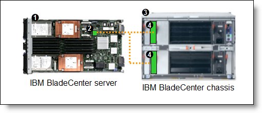
Figure 2. Using IBM BladeCenter Ethernet Switch Modules to route the integrated Ethernet ports
Table 4 lists the components that are used in the two-port configuration shown in Figure 2.
Table 4. Components used in the two-ports-per-server configuration
Four-port configuration
Figure 3 shows the use of BladeCenter Ethernet Switch Modules to route four Ethernet ports from each server: the two integrated ports plus two ports supplied by a compatible CFFv or CIOv expansion card. Four Ethernet Switch Modules are installed in bay 1, bay 2, bay 3, and bay 4 of the BladeCenter chassis. All connections between the controller and card and the switch modules are internal to the chassis. No cabling is needed.
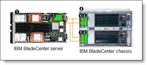
Figure 3. Using IBM BladeCenter Layer 2-7 Gigabit Ethernet Switch Module to route the four Ethernet ports from the integrated controller and a CFFv or CIOv expansion card
Table 5 lists the components that are used in the four-port configuration shown in Figure 3.
Table 5. Components used in the four-ports-per-server configuration
Basic two-port configuration
Figure 2 shows basic use of the Layer 2-7 Gigabit Ethernet Switch Module to route the two-port Ethernet controller that is integrated onto the blade server. Two Ethernet Switch Modules are installed in bay 1 and bay 2 of the BladeCenter chassis. The connections between the controller and the switch modules are internal to the chassis. No cabling is needed.
Figure 2. Using IBM BladeCenter Ethernet Switch Modules to route the integrated Ethernet ports
Table 4 lists the components that are used in the two-port configuration shown in Figure 2.
Table 4. Components used in the two-ports-per-server configuration
| Diagram reference | Part number / machine type | Description | Quantity |
| Varies | IBM BladeCenter HS22 or other server | 1 to 14 | |
| None | Ethernet controller on the system board of the server | 1 per server | |
| Varies | Any supported BladeCenter server (see Table 2) | 1 | |
| 32R1859 | IBM BladeCenter Layer 2-7 Gigabit Ethernet Switch Module | 2 |
Four-port configuration
Figure 3 shows the use of BladeCenter Ethernet Switch Modules to route four Ethernet ports from each server: the two integrated ports plus two ports supplied by a compatible CFFv or CIOv expansion card. Four Ethernet Switch Modules are installed in bay 1, bay 2, bay 3, and bay 4 of the BladeCenter chassis. All connections between the controller and card and the switch modules are internal to the chassis. No cabling is needed.
Figure 3. Using IBM BladeCenter Layer 2-7 Gigabit Ethernet Switch Module to route the four Ethernet ports from the integrated controller and a CFFv or CIOv expansion card
Table 5 lists the components that are used in the four-port configuration shown in Figure 3.
Table 5. Components used in the four-ports-per-server configuration
| Diagram reference | Part number / machine type | Description | Quantity |
| Varies | IBM BladeCenter HS22 or other supported server | 1 to 14 | |
| None | Ethernet controller on the system board of the server | 1 per server | |
| Varies | Compatible CFFv or CIOv expansion card (see Table 3) | 1 per server | |
| Varies | Any supported BladeCenter chassis (see Table 2) | 1 | |
| 32R1859 | Layer 2-7 Gigabit Ethernet Switch Module routing signals from the CFFv or CIOv card |
2 | |
| 32R1859 | Layer 2-7 Gigabit Ethernet Switch Module routing signals from the integrated controller |
2 |
Connectors and LEDs
Figure 4 shows the front panel of the Layer 2-7 Gigabit Ethernet Switch Module.
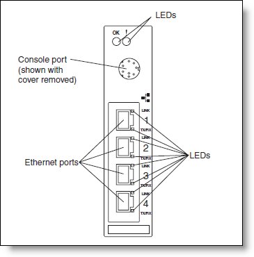
Figure 4. Front panel of the IBM BladeCenter Layer 2-7 Gigabit Ethernet Switch Module
The front panel contains the following components:
Figure 4. Front panel of the IBM BladeCenter Layer 2-7 Gigabit Ethernet Switch Module
The front panel contains the following components:
- Four external 1000BASE-T Ethernet ports for 10/100/1000 Mbps connections to external Ethernet devices.
- LEDs that display the status of the switch module and the network. These LEDs are:
- OK, which indicates that the switch module has passed the power-on self-test (POST) with no critical faults and is operational
- Switch module error, which indicates that the switch module has failed the POST or detected an operational fault.
- One RS-232 console port that provides an additional means to install software and configure the switch module. This 8-pin DIN connector allows connection of an 8-pin DIN to DB9 serial cable. The serial cable is supplied with the switch module. The protective cap must be removed while the console port is in use and should be reinstalled when the console cable is disconnected.
Network cabling requirements
The network cables required for the switch module are as follows:
- 10BASE-T:
- UTP Category 3, 4, 5 (100 meters (328 feet) maximum)
- 100-ohm STP (100 meters maximum)
- 100BASE-TX:
- UTP Category 5 (100 meters maximum)
- EIA/TIA-568 100-ohm STP (100 meters maximum)
- 1000BASE-T:
- UTP Category 6
- UTP Category 5e (100 meters maximum)
- UTP Category 5 (100 meters maximum)
- EIA/TIA-568B 100-ohm STP (100 meters maximum)
Related product families
Product families related to this document are the following:
Trademarks
Lenovo and the Lenovo logo are trademarks or registered trademarks of Lenovo in the United States, other countries, or both. A current list of Lenovo trademarks is available on the Web at https://www.lenovo.com/us/en/legal/copytrade/.
The following terms are trademarks of Lenovo in the United States, other countries, or both:
Lenovo®
BladeCenter®
The following terms are trademarks of other companies:
Microsoft® is a trademark of Microsoft Corporation in the United States, other countries, or both.
Other company, product, or service names may be trademarks or service marks of others.


